Performance Analysis of Solar Power
Optimizer for DC Distribution System
Dr. T. Muthamizhan
Associate Professor, Dept. of EEE, Bharath University, Chennai, Tamilnadu, India
ABSTRACT: Solar Power Optimizer for DC Distribution System is composed of a high step-up solar power optimizer (SPO), efficiently harvests maximum energy from a photovoltaic (PV) panel outputs energy to a dc-micro grid. Its structure integrates coupled inductor and switched capacitor technologies to realize high step-up voltage gain. The leakage inductance energy of the coupled inductor can be recycled to reduce voltage stress and power losses. A low voltage rating and low-conduction resistance switch improves system efficiency by employing the incremental conductance method for the maximum power point tracking (MPPT) algorithm. Because of its high tracking accuracy, the method is widely used in the energy harvesting of PV systems. The power reduction caused by the shadow effect on PV panels is an inevitable problem in a centralized PV system. The use of a micro inverter or ac module has recently been proposed for individual PV panels.
KEYWORDS: SPO, PV array, MPPT, Micro grid, PI Controller, Fuzzy Controller.
I.INTRODUCTION
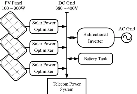
The Solar Power Optimizer for DC Distribution System,a development of photovoltaic (PV) power generation system, which uses a renewable resource, has been extensively used in emergency facilities and in generating electricity for mass use[1]. A conventional PV generation system is either a single- or a multi string PV array that is connected to one or several central PV inverters. Numerous series-connected PV modules are connected in the PV array to achieve the DC link voltage that is high enough to be connected to electricity through the DCAC inverter[2]-[3]. Though, reduction in power caused by the shadow effect is an unavoidablenature in a centralized PV system. The use of a micro inverter or ac module has recently been proposed for individual PV panels. Although this discrete PV power generation solution may partially eliminate the shadow problem, a micro inverter structure constrains the system energy’s harvesting efficiency and entails high costs [4]-[7]. The SPO attempts to improve the use of distributed renewable resources and lower system cost. It may also potentially improve the efficiency of PV systems, has an anti-shadow effect, and can monitor the status of PV modules. Moreover, the dc-grid voltage is regulated by bidirectional inverter and battery tank. [8-11] In case of low-loading condition, the redundant energy will store into battery or through bidirectional inverter to ac grid. A solar power optimizer (SPO) was developed as an alternative to maximize energy harvest from each individual PV module. [12-18].
ratio and the leakage inductor energy of the coupled inductor is efficiently recycled to the load explains the module's high-efficiency performance [25].
II.SOLAR POWER OPTIMIZER FOR DC DISTRIBUTION SYSTEM
Fossil fuels continue to be depleted, and their use has been instrumental to climate change, a problem that grows more severe each year. A photovoltaic (PV) power generation system, which uses a renewable resource, has been extensively used in emergency facilities and in generating electricity for mass use. A conventional PV generation system is either a single- or a multi string PV array that is connected to one or several central PV inverters. Numerous series-connected PV modules are connected in the PV array to achieve the DC link voltage that is high enough to be connected to electricity through the DCAC inverter. The decrease inoutput power caused by the shadow effect is an inevitable problem in a centralized PV system. The use of a micro inverter or ac module has been proposed in recent times for individual PV panels.Although this discrete PV power generation solution may partially eliminate the shadow problem, a micro inverter structure constrains the system energy’s harvesting efficiency and entails high costs.
Figure 1: Configuration of multiple parallel SPO for a dc-micro grid system.
A solar power optimizer is a DC-DC converter technology to maximize the energy harvesting from solar photovoltaic / wind turbine systems. Solar modules are connected in series in an array, they produce optimal power when all the modules performance is good. When temperature changes, or fall leaves, winter snow or shade covers part of a module, causes outputs less energy and underperform, modules heat up and drag down the performance of the other modules by squeezing the flow of energy through the array. This can cause the array to lose power. This drawback can overcome by using power optimizers. Power optimizers are DC-DC converters attached at the module level, correct for module “mismatch” by allowing each module to function at its maximum power point (MPP) and convert the energy to the optimal voltage and current for the array. This enables the entire array to yield more energy. The SPO can individually tuning the performance of the panel /wind turbine through maximum power point tracking techniques, and optimally tuning the output to match the performance of the string inverter. SPO’s are particularly used when the performance of the power generating components such as the PV Panel, Wind Generator in a distributed system will vary widely, differences in equipment, shading effect of light or wind, or being installed facing different directions or widely separated locations. Power optimizers for solar applications, can be similar to microinverters, in that both systems attempt to isolate individual panels in order to improve overall system performance. A power optimizer integrated with the solar panel into a solar module or a smart module . A microinverter essentially combines a power optimizer with a small inverter in a single case that is used on every panel, while the power optimizer leaves the inverter in a separate box and uses only one inverter for the entire array. The advantage of using this hybrid approach is lesser overall system costs and avoiding the distribution of electronics.
III.CONTROL OF PROPOSED SOLAR POWER OPTIMIZER
This method deals a high power application with low input voltage.The proposed SPO structure is based on a high step-up dc–dc converter with a MPPT control circuit. The converter includes a floating active switch S and a costep-upled inductor T1with primary winding N1, which is similar to the input inductor of a conventional boost converter capacitor
C1, and diode D1 recycle leakage inductance energy from N1. Secondary winding N2 is connected to capacitors, C2and
C3, and two diodes D2and D3. The Rectifier diode D4is connected to the output capacitor C0 and the load R. The duty
ratio is modulated by the MPPT algorithm, which uses PI and Fuzzy controller that is employed in the proposed SPO. It detects PV module voltage VPV and current IPVto determine the increase and decrease in the duty cycle of the dc
converter. The proposed converter has the following features
1. It is a voltage conversion ratio efficiently increased by using the switched capacitor and coupled inductor technique. 2. The leakage inductance energy of the coupled inductor can be recycled to increase efficiency, and the voltage spike
on the active switch is restrained.
3. The floating active switch S isolates the PV panel’s energy during non-operating conditions, thereby preventing any potential electric hazard to humans or facilities. The MPPT control algorithm exhibits high-tracking efficiency. Hence, it is widely used in the energy harvesting of PV systems.
The operating principles includes Continuous Conduction Mode (CCM) and Discontinuous Conduction Mode (DCM) with typical waveform of several major components in CCM operation during one switching period. To simplify the circuit investigation of the proposed converter, the following assumptions are made
1. All the components used in optimiser circuit are ideal, except for the leakage inductance of coupled inductor T1 is
taken into account. On-state resistance Rds (ON) and all the parasitic capacitances of main switch S are disregarded,
as are the forward voltage drops of diodes D1to D4.
2. Capacitors C1 to C3 and C0 are sufficiently large that the voltages across them are considered constant,
3. The equivalent series resistance (ESR) of capacitors C1 to C3 and C0, as well as the parasitic resistance of coupled
inductor T1, is neglected
4. Turns ratio n of coupled inductor is equal to N2/N1.
A solar power optimizer can be controlled by a number of techniques of which the PI and Fuzzy Logic controller are discussed in this paper.
IV.SIMULATION RESULTSAND DISCUSSION
Simulation has become a very powerful tool on the industry application as well as in academics, nowadays. It is now essential for an electrical engineer to understand the concept of simulation and learn its use in various applications. Simulation is one of the best ways to study the system or circuit behavior without damaging it .The tools for doing the simulation in various fields are available in the market for engineering professionals. Many industries are spending a considerable amount of time and money in doing simulation before manufacturing their product. In most of the research and development (R&D) work, the simulation plays a very important role. Without simulation it is quiet impossible to proceed further. It should be noted that in power electronics, computer simulation and a proof of concept hardware prototype in the laboratory are complimentary to each other. However computer simulation must not be considered as a substitute for hardware prototype using MATLAB tool.
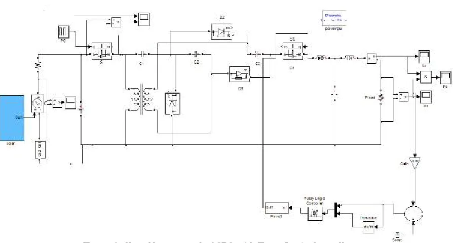
Figure 4: Closed loop control of SPO with Fuzzy Logic Controller
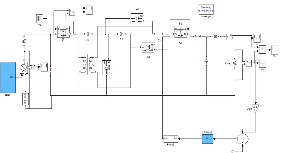
The closed loop control of the solar power optimizer system using PI controller and Fuzzy Logic Controller are as shown in the Figure 3 and Figure 4 respectively.
Figure 5: Input voltage to the SPO
The closed loop control of SPO using the PI controller are as shown from Figure 6 to Figure 9. The input voltage is shown in Figure 5, where there is a step change in the input voltage at time T=1 Seconds.
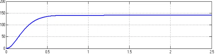
Figure 6: Output voltage of the SPO using PI Controller
Figure 7: Output current of the SPO using PI Controller
The output currentin Figure 7 shows the disturbance around 1.5 Seconds for the step change in the input voltage.
Figure 8:Output power of the converter using PI Controller
The output power as in Figure 8 shows the variation of the output power with respect to power, and the disturbance here in the output power due to change in the input voltage is noted.
Figure 9: Input voltage to the SPO
Similarly, the closed loop control of SPO usingFuzzy Logic controller are explained with the help of step change input voltage from Figure 9 to Figure 12, where figure 9 shows the input voltage to the SPO.
The input voltage is shown in Figure 9, where there is a step change in the input voltage at time T=1 Seconds. The output voltage is shown in Figure 10, where a step change in the input put voltage at time T=1 Seconds cause the output voltage change disturbed and reach the same voltage at the same time.
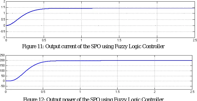
Figure 11: Output current of the SPO using Fuzzy Logic Controller
Figure 12: Output power of the SPO using Fuzzy Logic Controller
The Figure 11 and Figure 12 shows the output currentand output power curves, at time t=1 seconds the current and power reaches the set value as soon as they are disturbed in Fuzzy Logic Controller.
Table I: Summary of the time domain parameters
Converter Tr Ts Tp Vp Ess
PI controller 0.4 2 1.6 5 2.8
Fuzzy controller 0.24 0.6 0 0.06 0.08
Table I gives the summary of the time domain parameters rise time, settling time, peak time, peak voltage and steady state error. The rise time for a fuzzy controller is 0.24 seconds whereas it is 0.4 seconds in PI controller and the settling time of fuzzy controller is 0.6 Seconds and 2 seconds for PI controller. The steady state error for PI controller is 2.8 seconds and 0.08 seconds for fuzzy controller.
V.CONCLUSION
The high step-up SPO uses the coupled inductor with anappropriate turn’s ratio design and switched-capacitor technology toachieve a high-voltage gain that is 20 times higher than the input voltage.The proposed circuit elements are designed usingrelated equations, developed using the functional components of Simulinklibrary. The Simulation is successfully done by closed loop PI and Fuzzy controller. The closed loop system are simulated and theirresults are presented. From the Table I, it is concluded that the response of FuzzyLogic Controller in solar power optimizer is superior than aPI controlledsystem.
REFERENCES
[1] Y. Fang and X. Ma, “A novel PV micro inverter with coupled inductors and double-boost topology,” IEEE Trans. Power Electron., vol. 25, no. 12, pp. 3139–3147, 2010.
[3] P. Tsao, “Simulation of PV systems with power optimizers and distributed power electronics,” in Proc. IEEE Photovolt. Spec. Conf., pp. 389– 393, 2010.
[4] D. D.-C. Lu and V. G. Agelidis, “Photovoltaic-battery-powered DC bus system for common portable electronic devices,” IEEE Trans. Power Electron., vol. 24, no. 3, pp. 849–855, 2009.
[5] L. Zhang, K. Sun,Y. Xing, L. Feng, andH.Ge, “A modular grid-connected photovoltaic generation system based on DC bus,” IEEE Trans. Power Electron., vol. 26, no. 2, pp. 523–531, 2011.
[6] S. M. Chen, K. R. Hu, T. J. Liang, L. S. Yang, and Y. H. Hsieh, “Implementation of high step-up solar power optimizer for DC micro grid application,” in Proc. IEEE Appl. Power Electron Conf., pp. 28–32, 2012.
[7] A. Pratt, P. Kumar, and T. V. Aldridge, “Evaluation of 400 V DC distribution in telco and data centers to improve energy efficiency,” in Proc. IEEE Int. Telecommun. Energy Conf., pp. 32–39, 2007.
[8] L. Zhang, K. Sun,Y. Xing, L. Feng, andH.Ge, “A modular grid-connected photovoltaic generation system based on DC bus,” IEEE Trans. Power Electron., vol. 26, no. 2, pp. 523–531, 2011.
[9] S.M. Chen, T. J. Liang, L. S. Yang, and J. F. Chen, “A boost converter with capacitor multiplier and coupled inductor for AC module applications,” IEEE Trans. Ind. Electron., Early Access Articles, vol.60, no. 4, pp. 1503-1511, 2013.
[10] A. C. Nanakos, E. C. Tatakis, and N. P. Papanikolaou, “A weighted efficiency- oriented design methodology of flyback inverter for AC photovoltaic modules,” IEEE Trans. Power Electron., vol. 27, no. 7, pp. 3221–3233, 2012.
[11] S. Zengin, F. Deveci, and M. Boztepe, “Decoupling capacitor selection in DCM fly-back PV micro-inverters considering harmonic distortion,” IEEE Trans. Power Electron., Early Access Articles, vol.28, no. 2, pp.816-825, 2013.
[12] B. Axelrod, Y. Berkovich, and A. Ioinovici, “Switched-capacitor/switched-inductor structures for getting transformerless hybrid DC-DC PWM converters,” IEEE Trans. Circuits Syst. I, Reg. Papers, vol. 55, no. 2, pp. 687–696, 2008.
[13] O. Abutbul, A. Gherlitz, Y. Berkovich, and A. Ioinovici, “Step-up Switching mode converter with high voltage gain using a switched- capacitor circuit,” IEEE Trans. Syst. I, Fundam. Theory Appl., vol. 50, no. 8, pp. 1098–1102, 2003.
[14] S. C. Tan, S. Bronstein, M. Nur, Y. M. Lai, A. Ioinovici, and C. K. Tse, “Variable structure modeling and design of switched-capacitor converters,” IEEE Trans. Circuits Syst. I, Reg. Papers, vol. 56, no. 9, pp. 2132– 2142, 2009.
[15] G. Zhu and A. Ioinovici, “Switched-capacitor power supplies: DC voltage ratio, efficiency, ripple, regulation,” in Proc. IEEE Int. Symp. Circuits syst., pp. 553–556, 1996.
[16] F. L. Luo, “Switched-capacitorized DC/DC converters,” in Proc. IEEE Conf. Ind. Electron. Appl., May 2009, pp. 1074–1079.
[17] L. S.Yang, T. J. Liang, and J. F.Chen, “TransformerlessDC-DC converters with high step-up voltage gain,” IEEE Trans. Ind. Electron., vol. 56, no. 8, pp. 3144–3152, 2009.
[18] B. Axelrod, Y. Berkovich, and A. Ioinovici, “Transformerless DC-DC converters with a very high DC line-to-load voltage ratio,” in Proc. IEEE Int. Symp. Circuits syst., vol. 3, pp. 435–438, 2003.
[19] F. L. Luo and H. Ye, “Positive output multiple-lift push-pull switched capacitor Luo-converters,” IEEE Trans. Ind. Electron., vol. 51, no. 3, pp. 594–602, 2004.
[20] M. Zhu and F. L. Luo, “Enhanced self-lift cˆuk converter for negative-to positive voltage conversion,” IEEE Trans. Power Electron., vol. 25, no. 9, pp. 2227–2233, 2010.
[21] Y. Jiao, F. L. Luo, and M. Zhu, “Voltage-lift-type switched-inductor cells for enhancing DC-DC boost ability: Principles and integrations in Luo converter,” IET Trans. Power Electron., vol. 4, no. 1, pp. 131–142, 2011.
[22] J. W. Baek, M. H. Ryoo, T. J. Kim, D. W. Yoo, and J. S. Kim, “High boost converter using voltage multiplier,” in Proc. Annu. IEEE Conf. Ind. Electron. Soc., pp. 567–572,2005.
[23] R. J.Wai and R. Y. Duan, “High step-up converter with coupled-inductor,” IEEE Trans. Power Electron., vol. 20, no. 5, pp. 1025–1035, 2005. [24] S. K. Changchien, T. J. Liang, J. F. Chen, and L. S. Yang, “Novel high step-up DC–DC converter for fuel cell energy conversion system,”
IEEE Trans. Ind. Electron., vol. 57, no. 6, pp. 2007–2017, 2010.
[25] S. M. Chen, T. J. Liang, L. S. Yang, and J. F. Chen, “A safety enhanced, high step-up DC-DC converter for AC photovoltaic module application,” IEEE Trans. Power Electron., vol. 27, no. 4, pp. 1809–1817, 2012.
BIOGRAPHY