80000INS07 April 2001 (2106)
Hardware Manual
2. PCB Installation 3. Installing 4. Optional 5. Maintenance 6. Specifications 1. Installing the
This manual has been developed by NEC America, Inc. It is intended for the use of its customers and service personnel, and should be read in its entirety before attempting to install or program the system. Any com-ments or suggestions for improving this manual would be appreciated. Forward your remarks to:
NEC America, Inc., Corporate Networks Group 4 Forest Parkway
Shelton, CT 06484 cng.nec.com
Nothing contained in this manual shall be deemed to be, and this manual does not constitute, a warranty of, or representation with respect to, any of the equipment covered. This manual is subject to change without notice and NEC America, Inc. has no obligation to provide any updates or corrections to this manual. Further, NEC America, Inc. also reserves the right, without prior notice, to make changes in equipment design or components as it deems appropriate. No representation is made that this manual is complete or accurate in all respects and NEC America, Inc. shall not be liable for any errors or omissions. In no event shall NEC America, Inc. be liable for any incidental or consequential damages in connection with the use of this manual. This document contains proprietary information that is protected by copyright. All rights are reserved. No part of this document may be photocopied or reproduced without prior written consent of NEC America, Inc.
1. Installing the
1-1
In this section
. . .
Page
RFI Suppressor Assemblies . . . .1-14
Installing the RFI Suppressor Assemblies . . . 1-14Power Supply Installation . . . .1-16
Installing the Power Supply . . . 1-16System Configuration - U Slot . . . .1-17
U Slot Configuration Guidelines . . . 1-17 System Load Factor Calculations . . . 1-18 U Slot Default Settings . . . 1-19System Configuration - Fixed Slot . . . .1-20
Fixed Slot Configuration Guidelines . . . 1-20 Fixed Slot Default Settings . . . 1-20In this section
. . .
Page
Installing the Cabinet . . . .1-3
Unpacking . . . 1-3 Before Installing . . . 1-3 Site Requirements. . . 1-3 Planning the Installation for a 4 Slot MainEquipment Cabinet . . . 1-4 Planning the Installation for an 8 Slot Main
Equipment Cabinet . . . 1-5 Removing the Cover. . . 1-7 Unpacking the Wall Mount Bracket . . . 1-8 Mounting the Wall Mount Bracket . . . 1-8 Hanging the Cabinet . . . 1-9
Grounding the Cabinet . . . .1-11
Removing the Right Side Panel. . . 1-11 Attaching the Ground Wires . . . 1-131. Installing the
1-3
Unpacking
Unpack the equipment and check it against your equipment lists. Inspect for physical damage. If you are not sure about a compo-nent’s function, review the Product Description Manual. Contact your Sales Representative if you have additional questions.
Have the appropriate tools for the job on hand, including: a test set, a punch down tool and a digital voltmeter.
Before Installing
Make sure you have a building plan showing the location of the common equipment, extensions, the telco demarcation and earth ground. In addition, the installation site must meet the requirements outlined in the Standard Practices Manual.
Site Requirements
The common equipment is contained in the wall-mounted Main Equipment Cabinet. Choose a central location for the cabinet that allows enough space for the equipment — and provides enough room for you to comfortably work. The Installation Layout (Figures 1-1 and 1-2) shows you about how much space your system requires.
1-4
Planning the Installation for a 4 Slot Main
Equipment Cabinet (Figure 1-1)
Before installing the common equipment, you should mount a Main Distribution Frame (MDF) plywood backboard in a cen-trally located spot. A 1/2 sheet of plywood (4’ x 4’) should be more than adequate. Mount this backboard using suitable fas-teners, taking care to adhere to standard installation practices and local codes.
The equipment cabinet requires a three-prong, dedicated 110 VAC 60 Hz circuit (NEMA 5-15 receptacle) located within 7 feet of the AC receptacle.
Normally, you install the extension and trunk blocks to the right of the Main Cabinet. Telco should also install the RJ21X to the right of the Main Cabinet.
Figure 1-1 4 SLOT INSTALLATION LAYOUT
80000 - 15A
Plywood backboard
Dedicated AC Outlet Surge
Protector
To earth ground To telco
ground
Station
Blocks StationBlocks Trunk
Blocks 4’
4’
1. Installing the
1-5
Planning the Installation for an 8 Slot Main
Equipment Cabinet (Figure 1-2)
Before installing the common equipment, you should mount a Main Distribution Frame (MDF) plywood backboard in a cen-trally located spot. A full sheet of plywood (8’ x 4’) should be more than adequate. Mount this backboard using suitable fas-teners, taking care to adhere to standard installation practices and local codes.
The equipment cabinet requires a three-prong, dedicated 110 VAC 60 Hz circuit (NEMA 5-15 receptacle) located within 7 feet of the AC receptacle.
Normally, you install the extension and trunk blocks to the right of the Main Cabinet. Telco should also install the RJ21X to the right of the Main Cabinet.
1-6
INSTALLING THE CABINET
Figure 1-2 8 SLOT INSTALLATION LAYOUT
80000 - 61
8’ X 4’ Plywood backboard
Surge
Protector To telcoground To earthground
Station Blocks Trunk
Blocks
Station Blocks
1. Installing the
1-7
Removing the Cover (Figure 1-3)
Before wall-mounting, remove the cover on the Main Equipment Cabinet.
1. Unscrew the two captive screws on the front of the cabinet cover.
2. Lift up slightly on the front of the cover — then gently slide the cover back to remove it.
Figure 1-3 REMOVING THE COVER
80000 - 12
INSTALLING THE CABINET
1-8
Unpacking the Wall Mount Bracket (Figure 1-4)
The wall mount bracket and screws are taped to the packing mater-ial in the Main Equipment Cabinet box. Unpack the wall mount bracket and mounting screws.
Figure 1-4 WALL MOUNT BRACKET
Mounting the Wall Mount Bracket (Figure 1-5)
Mount the wall mount bracket on the MDF in a convenient loca-tion, about 12” higher than where you want the bottom of the cabi-net to line up.
Figure 1-5 MOUNTING THE WALL MOUNT BRACKET
80000 - 14
80000 - 1 1
1. Installing the
1-9
Hanging the Cabinet (Figures 1-6 and 1-7)
1. Hang the Main Equipment Cabinet on the wall mount hang-er as shown:
● See Figure 1-6 when hanging a 4 slot cabinet.
● See Figure 1-7 when hanging an 8 slot cabinet.
2. Using the remaining screws that were packed with the hang-er, secure the cabinet to the plywood backboard.
Figure 1-6 HANGING THE 4 SLOT CABINET
80000 - 13
1-10
INSTALLING THE CABINET
1. Installing the
1-11
GROUNDING THE CABINET
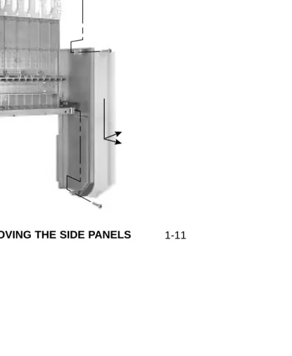
Removing the Right Side Panel (Figure 1-8)
Remove the cabinet right side panel to gain easy access to the ground lugs and system cabling. The cabinet has two ground connections: ETH (Earth Ground) and PBXG (PBX Ground). 1. Remove the two screws that secure the right side panel to
the cabinet.
2. Carefully slide the right side panel down until it swings clear of the cabinet.
Figure 1-8 REMOVING THE SIDE PANELS
80000 - 16
1-12
GROUNDING THE CABINET
1. Installing the
1-13
GROUNDING THE CABINET
Attaching the Ground Wires (Figure 1-9)
The system provides two ground terminations. Each ground connects from the system to the ground termination using 12 AWG stranded copper wire (see Figure 1-9).
● Use the ETH (Earth Ground) for safety/system ground. You
must connect ETH to a known earth ground.
● Use the PBXG (PBX Ground) if you have trunks that require telco ground (such as ground start trunks). This ground is not required for loop start trunks.
1. Remove the lug on the ground connection you want to connect. 2. Follow Figure 1-10 and run the ground wire(s) through the
RFI Suppressor Assembly as shown. 3. For Earth Ground:
Run a ground wire from the ETH lug to a known earth ground.
For PBX Ground:
Run a ground wire from the PBXG lug to the telco ground. 4. Crimp ring terminals as required to the ground wires. 5. Reinstall and firmly tighten the lug(s) removed in step 1 above.
Do not plug in the power cord or reinstall the right side panel until all PCB installation and cabling are complete.
Figure 1-9 ATTACHING THE GROUND WIRES
80000 - 17
To earth ground
To telco ground
1-14
RFI SUPPRESSOR ASSEMBLIES
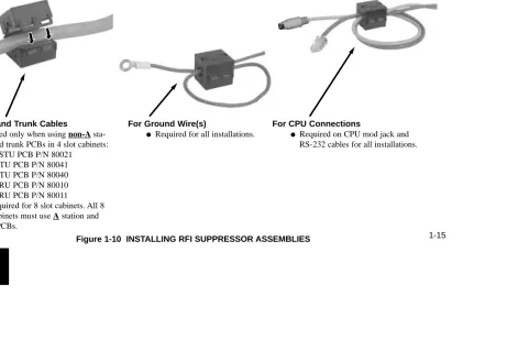
Installing RFI Suppressor Assemblies (Figure 1-10)
You must install RFI Suppressor Assemblies as follows. The suppressors must be mounted inside the cabinet and as close to the appropriate PCB as possible.
● For Station and Trunk Cables
— Only install these assemblies if you are installing non-A station and trunk PCBs in a 4 slot cabinet. If you have a mixture of A and non-A PCBs, you only need to install the assemblies on the non-A PCBs.
— RFI assemblies on station and trunk cables are not required with 8 slot cabinets, since these cabinets use only
A PCBs. ● For Ground Wires
— You must install a separate RFI assembly for the ground wire(s) in all systems.
— If your system has 2 ground wires, install them both in the same assembly.
● For CPU Connections
— You must install a separate RFI assembly for the CPU mod jack and RS-232 cables in all systems. Install both cables in the same assembly.
ow!!
he
RS- f-onal
able. s
1. Installing the
1-15
RFI SUPPRESSOR ASSEMBLIES
80000 - 67
Figure 1-10 INSTALLING RFI SUPPRESSOR ASSEMBLIES For Station and Trunk Cables
● Required only when using non-A sta-tion and trunk PCBs in 4 slot cabinets: —16DSTU PCB P/N 80021
—8ASTU PCB P/N 80041 —4ASTU PCB P/N 80040 —4ATRU PCB P/N 80010 —8ATRU PCB P/N 80011
● Not required for 8 slot cabinets. All 8 slot cabinets must use A station and trunk PCBs.
For CPU Connections
● Required on CPU mod jack and RS-232 cables for all installations.
For Ground Wire(s)
1-16
POWER SUPPLY INSTALLATION
Installing the Power Supply (Figures 1-11 and 1-12)
The power supply provides the DC power sources required to operate the system:
1. Slide the power supply into the CN101 slot as shown at right.
2. Using a long-shaft phillips head screwdriver, tighten the two screws that secure the power supply.
An 8 slot cabinet may require up to 3 power supplies, using slots CN101, CN102 and CN103. Refer to System Configuration on page 1-17 for more.
Figure 1-11 POWER SUPPLY Figure 1-12 Installing the Power Supply
80000 - 29
1. Installing the
1-17
SYSTEM CONFIGURATION - U SLOT
U Slot Configuration Guidelines
U Slot systems use software version 02.**.** or higher.
The total number of components you can install and connect depends on power supply capacity and the System Load Factor. Review the Configuration Guidelines at right and System Load
Factor Calculations on page 1-18 when configuring your
sys-tem. Also read U Slot Default Settings on page 1-19. You may find that the default setup is adequate for your needs.
Also see Where to Install the PCBs in your U Slot System on page 2-2.
Notes for U Slot Software
● U Slot (02.nn.nn) software is available with both 4 and 8 slot cabinets.
4 Slot Cabinets
● Do not install more than 2 16DSTU PCBs installed under any circumstances.
● The rst 16DSTU PCB you install must be in the rst slot.
● You can install up to 40 extensions maximum, as follows:
(2) 16DSTU PCBs = 32 digital extensions (1) 8ASTU PCB = 8 analog extensions Total = 40 extensions
● You can install up to 24 trunks maximum, as follows:
(3) 8ASTU PCBs = 24 analog trunks
● Maximum con guration is 48ports.
● The total of all extensions and trunks cannot exceed 48.
● Always use the System Load Factor Table to check you system con guration.
8 Slot Cabinets
● Do not install more than 2 16DSTU PCBs for each power supply.
● The rst 16DSTU PCB you install must be in the rst slot (CN1).
● You can install up to 96 extensions maximum.
● You can install up to 48 trunks maximum.
● The total of all extensions and trunks installed cannot exceed 104.
● Maximum con guration is 104 ports.
● 8-slot cabinet require, A series PCBs, as follows:
CPU PCB P/N 80025A Power Supply P/N 80005A
16DSTU Digital Station PCB P/N 80021A 8 ASTU 8 Port Analog Station PCB P/N 80041A 4ASTU 4 Port Analog Station PCB P/N 80040A 8ATRU 8 Port Analog Trunk PCB P/N 80011A 4ATRU 4 Port Analog Trunk PCB P/N 80010A
1-18
System Load Factor Calculations
To check your system configuration:
1. In the table at right, indicate the quantity for each item installed in the Qtycolumn.
2. For each item, multiply the Qtytimes the Load Factor and enter the value in the Total Loadcolumn.
3. Add all the values in the Total Loadcolumn and enter the value in Item 1.
4. Determine the System Load Factor capacity of the power supplies installed in your system and enter the total in Item 2.
A 4-slot cabinet can have only 1 power supply. An 8-slot cabinet can have up to 3 power supplies. You can-not have more than two 16DSTU PCBs per power sup-ply, regardless of System Load Factor calculations. Exceeding the System Load Factor will cause the sys-tem’s power supplies to automatically shut down.
5. Compare the entry in Item 2to your entry in Item 1. Item 1 must always be equal to or less than the entry in Item 2.
Do not operate your system if the System Load Factor total (Item 1) exceeds the allowable value (Item 2).
SYSTEM CONFIGURATION - U SLOT
System Load Factor Calculations
Description Load Factor Qty Total Load
16DSTU PCB 16
4ASTU PCB 8
8ASTU PCB 12
110-Button DSS Console 2
24-Button DSS Console 1
Total DSS Consoles installed cannot exceed 4.
2-OPX Module 3
Item 1: Total load for this con guration:
Item 2: If you have one power supply installed, enter 48. If you have two power supplies installed, enter 80. If you have three power supplies installed, enter 112. (2 16DSTU PCBs maximum per power supply)
1. Installing the
1-19
SYSTEM CONFIGURATION - U SLOT
U Slot Default Settings
If you have a U Slot system (software version 02.**.**), fol-lowing are the default configurations. If you have a fixed slot system (software 01.**.**), turn to page 1-20.
● 4 Slot Cabinet with CPU P/N 80025
Default configuration: 16 trunks x 32 extensions Slot CN1 = 16 DSTU PCB (Extensions 300-315) Slot CN2 = 16 DSTU PCB (Extensions 316-331) Slot CN3 = 8 ATRU PCB (Trunks 1-8)
Slot CN4 = 8 ATRU PCB (Trunks 9-16)
● 4 Slot Cabinet with CPU P/N 80025A
Default configuration: 0 trunks x 64 extensions Slot CN1 = 16 DSTU PCB (Extensions 300-315) Slot CN2 = 16 DSTU PCB (Extensions 316-331) Slot CN3 = 16 DSTU PCB (Extensions 332-347) Slot CN4 = 16 DSTU PCB (Extensions 348-363) Notes on this configuration:
1. Slots CN5-CN8 are not available.
2. You cannot install this configuration as is; it has too many 16DSTU PCBs. You must use 9902: Slot Control to recon-figure your PCBs. See your system’s Release Notes or
Software Manual for more on using 9902: Slot Control.
● 8 Slot Cabinet with CPU P/N 80025A
Default configuration: 24 trunks x 80 extensions Slot CN1 = 16 DSTU PCB (Extensions 300-315) Slot CN2 = 16 DSTU PCB (Extensions 316-331) Slot CN3 = 16 DSTU PCB (Extensions 332-347) Slot CN4 = 16 DSTU PCB (Extensions 348-363) Slot CN5 = 16 DSTU PCB (Extensions 364-379) Slot CN6 = 8 ATRU PCB (Trunks 1-8)
Slot CN7 = 8 ATRU PCB (Trunks 9-16) Slot CN8 = 8 ATRU PCB (Trunks 17-24)
Notes on this configuration:
1-20
SYSTEM CONFIGURATION - FIXED SLOT
Fixed Slot Configuration Guidelines
Fixed Slot systems use software version 01.**.**. The maxi-mum configuration of your fixed slot system is 16 trunks and 32 extensions. Also see Where to Install the PCBs in your Fixed
Slot System on page 2-5.
Load factor in your fixed slot system is an issue only if you have DSS Consoles and 2-OPX Modules installed (see the
System Load Factor Calculations chart on page 1-18). Exceeding the load factor will cause your system’s power supply to automatically shut down.
Fixed Slot Default Settings
If you have a Fixed Slot system (software version 01.**.**), following is the default configuration. If you have a U Slot sys-tem (software 02.**.**), turn to page 1-17.
● 4 Slot Cabinet with Fixed Slot Software and CPU P/N 80025
Default configuration: 16 trunks x 32 extensions Slot CN1 = 16 DSTU PCB (Extensions 300-315) Slot CN2 = 16 DSTU PCB (Extensions 316-331) Slot CN3 = 8 ATRU PCB (Trunks 1-8)
Slot CN4 = 8 ATRU PCB (Trunks 9-16)
Notes on this configuration:
1. You can plug DSTU PCBs only into slots CN1 and CN2. 1. You can only plug an ASTU PCB only into slot CN2 (in
place of the second DSTU PCB).
2. Install ATRU PCBs only into slots CN3 and CN4.
Notes for Fixed Slot Software
● Fixed slot (01.nn.nn) software is only compatible with 4 slot cabinets.
● Fixed slot software is no longer available, but you may encounter it in existing installations.
● You can plug 16DSTU PCBs only into slots CN1 and CN2. Do not install more than 2
16DSTU PCBs under any circumstances.
● You can plug an ASTU PCB only into slot CN2 (in place of the second DSTU PCB).
● Install ATRU PCBs only into slots CN3 and CN4.
● System Load Factor in Fixed Slot systems is only an issue if you have DSS Consoles and
2-OPX Modules installed. Note that you cannot install more than 4 DSS Consoles, regardless of System Load Factor.
● The Release Notes that came with your system indicate if it uses Fixed Slot software.
● Check your system s Hardware Manual for more installation details.
● Maximum con guration for 4-slot cabinets with Fixed Slot software is 16 trunks, 32
2-1
Section 2, PCB INSTALLATION AND STARTUP
In this section . . .
Page
Installing PCBs
(cont’d)Analog Trunk (8ATRU and 4ATRU) PCB . . 2-11 8 Circuit Caller ID Daughter Board . . . 2-12 4 Circuit Caller ID Daughter Board . . . 2-14
Connecting Blocks . . . .2-16
Working with 8-Pin Jacks . . . 2-16 Punching Down the Cables . . . 2-16 Making your own Cables . . . 2-16In this section . . .
Page
PCB Location - U Slot . . . .2-2
Where to Install the PCBs in yourU Slot System. . . 2-2
PCB Location - Fixed Slot . . . .2-5
Where to Install the PCBs in your
Fixed Slot System. . . 2-5
Installing PCBs . . . .2-7
Central Processing Unit (CPU) PCB . . . 2-7 Installing the CPU . . . 2-8 Digital Station (16DSTU) PCB. . . 2-9 Analog Station (8ASTU and 4ASTU) PCBs . 2-10!! Important !!
PCB LOCATION - U SLOT
2-2
Where to Install the PCBs in your U Slot System
(Figures 2-1 and 2-2)
Review System Configuration - U Slot on page 1-17 before installing any PCBs.
● When installing PCBs in a U Slot 4 slot system, follow Figure 2-1. You must install a 16DSTU in slot CN1.
● When Installing PCBs in a U Slot 8 slot system, follow Figure 2-2. You must install a 16DSTU in slot CN1.
Item Description Location Max.
CPU Central Processing Unit CN0 1
16DSTU 16 Digital Stations CN1 1
All other PCBs CN2-CN8 7
Caution
Do not plug in the CPU PCB hot (i.e., with the
system power applied).
You can plug in ASTU and ATRU PCBs hot as
required.
2-3
PCB LOCATION - U SLOT
Figure 2-1 4 SLOT PCB LOCATION Power Supply CPU 16DSTU (300-315) 16DSTU (316-331) 16DSTU (332-347) 16DSTU (348-363)
80000 - 58
P/N 80005/A P/N 80025A P/N 80021/A Power Supply CPU 16DSTU (300-315) 16DSTU (316-331) 8ATRU (1-8) 8ATRU (9-16)
80000 - 58
P/N 80005/A
P/N 80025
P/N 80021/A
P/N 80021/A
P/N 80011/A Ext. 401-408
P/N 80011/A Ext. 409-416
Default U Slot setup with CPU P/N 80025
Delete this slot!
Delete this slot! Delete this slot!
Default U Slot setup with CPU
P/N 80025A
!! Important !!
2 16DSTU PCBs maximum allowed in this configuration.
!! Important !!
2 16DSTU PCBs maximum allowed in this configuration. !! Important Note for 4 Slot Cabinets with CPU P/N 80025A !!
Your system slot assignments must be reprogrammed:
● Using 9902 - Slot Control, delete slots 2-8 and reprogram your slot assignments as required.
Even though your system has only 4 slots, slots 2-8 exist the data base and must be reprogrammed.
● Slot 1 is permanently assigned as the system s first 16DSTU PCB and cannot be changed.
PCB LOCATION - U SLOT
2-4 Power Supply
Power Supply (if required)
Power Supply (if required)
CPU
16DSTU PCB (300-315)
16DSTU PCB (316-331) 16DSTU PCB (332-347)
16DSTU PCB (348-363) 16DSTU PCB (364-379)
8ATRU PCB (1-8) 8ATRU PCB (9-16) 8ATRU PCB (17-24)
80000 - 59
P/N 80005A
P/N 80005A
P/N 80005A
P/N 80025A
P/N 80021A
P/N 80021A P/N 80021A
P/N 80021A P/N 80021A
P/N 80011A Ext. 401-408 Ext. 409-416 Ext. 415-424
P/N 80011A P/N 80011A
!! Important !! When plugging in PCBs:
● Use the default assignments shown in the illustration below.
OR
● Using 9902 - Slot Control, delete slots 2-8 and reprogram your slot assignments as required.
● Slot 1 is permanently assigned as the system s first 16DSTU PCB and cannot be changed.
Defaults shown
2-5
PCB LOCATION - FIXED SLOT
Where to Install the PCBs in your Fixed Slot
System (Figure 2-3)
Maximum Configuration: 16 Trunks
32 Extensions
Follow the chart below and Figure 2-3 when installing PCBs.
Item Description Location Max.
CPU Central Processing Unit CN0 1
16DSTU 16 Digital Stations CN1 and CN2 2
ASTU 4 or 8 Analog Stations CN2 1
8ATRU 8 Analog Trunks CN3 and CN4 2
Figure 2-3 FIXED SLOT PCB LOCATION Power Supply
CPU
16DSTU (300-315)
16DSTU (316-331) 4ASTU (316-319) 8ASTU (316-323)
8ATRU (1-8)
8ATRU (9-16)
80000 - 28
Caution
Do not plug in the CPU PCB hot (i.e., with the
system power applied).
You can plug in ASTU and ATRU PCBs hot as
required.
PCB LOCATION - FIXED SLOT
2-7
INSTALLING PCBs
Central Processing Unit (CPU) PCB (Figure 2-4)
The CPU provides:
●The system’s central processing, stored program and memory for the customer’s site-specific data.
●PC Card interface.
●Conference circuits, DTMF receivers and DTMF generators.
●External music input and on-board synthesized music source.
●External paging output and associated relay.
●Real Time Clock
● Battery for short term (14 day) backup of the customer’s site-specific data.
Figure 2-4 CPU PCB
d
on
ul-INSTALLING PCBs
2-8
Installing the CPU (Figures 2-5 and 2-6)
CPU PCB installs in the CN0 slot in the Main Equipment Cabinet.
●To install the CPU PCB:
1. Slide the Mode Switch to the RUN position (see Figure 2-5).
2. Insert the battery into the battery clips.
3. Plug the CPU into slot CN0 (see Figure 2-6).
Refer to Part 4, Installing
Optional Equipment for
instructions on connecting the music source, External Paging and the auxiliary relay.
Figure 2-5 Setting up the CPU Figure 2-6 INSTALLING THE CPU
8000 0 - 3
0
80
00
0 - 2
6
Battery Mode Switch
2-9
INSTALLING PCBs
Digital Station (16DSTU) PCB (Figures 2-6 and 2-7)
The 16DSTU provides connection for 16 digital telephones. Refer to Section
3, Installing Extensions and Trunks for
wiring instructions.
●To install the 16DSTU PCB:
1. Plug the 16DSTU PCB for exten-sions 300-315 into slot CN1. 2. Plug in additional 16DSTU PCBs as
required. See System Configuration in Section 1 for more.
3. Set the mode switch on each installed 16DSTU to RUN.
Figure 2-6 DIGITAL STATION (16DSTU) PCB Figure 2-7 INSTALLING THE 16DSTU PCB
80000 - 31
Mode Switch
INSTALLING PCBS
2-10
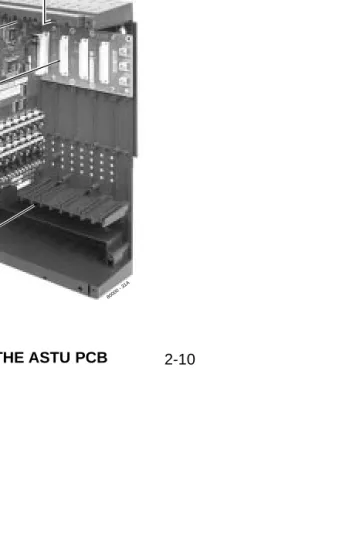
Analog Station (8ASTU and 4ASTU) PCBs
(Figures 2-8 and 2-9)
The 8ASTU PCB provides connection for 8 analog extensions. The 4ASTU PCB connects 4 analog extensions. Refer to Section 3, Installing Extensions
and Trunks for wiring instructions. ●To install the ASTU PCB:
1. Plug in ASTU PCBs as required.
In U Slot systems, see System Configuration in Section 1. In Fixed Slot systems, you can only plug an ASTU PCB into slot CN2. An 8ASTU PCB provides analog extensions 316-323. A 4ASTU PCB provides analog extensions 316-319.
2. Set the mode switch on the ASTU to RUN.
Figure 2-8 ANALOG STATION (ASTU) PCB Figure 2-9 INSTALLING THE ASTU PCB
80000 - 31A
Mode Switch
2-11
INSTALLING PCBs
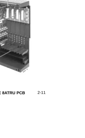
Analog Trunk (8ATRU and 4ATRU) PCBs
(Figures 2-10 and 2-11)
The 8ATRU provides connection for 8 loop start analog trunks. The 4ATRU PCB connects 4 loop start analog trunks. Refer to Section 3, Installing Extensions
and Trunks for wiring instructions. ●To install ATRU PCBs:
1. Install ATRU PCBs as required.
In U Slot systems, see System Configuration in Section 1. In Fixed Slot systems, plug the 8ATRU PCB for trunks 1-8 into slot CN3. Plug the 8ATRU PCB for trunks 9-16 into slot CN4. In Fixed Slot systems, a 4ATRU PCB enables the first 4 trunks (1-4) but disables the second 4 (5-8). With 2 4ATRU PCBs installed, you system has trunks 1-4 and 9-12.
3. Set the mode switch on each installed 8ATRU to RUN.
Figure 2-10 ANALOG TRUNK (ATRU) PCB Figure 2-11 INSTALLING THE 8ATRU PCB
80000 - 32
Mode Switch
INSTALLING PCBs
2-12
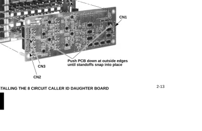
8 Circuit Caller ID Daughter Board (Figure 2-12)
For Caller ID capability, install 8 circuit Caller ID PCB daugh-ter boards (P/N 80013) on the 8ATRU PCBs (P/N 80011A). The Caller ID PCB provides Caller ID capability for all eight trunk circuits on the 8ATRU PCB. Every 8ATRU PCB in the system can have a Caller ID daughter board.
If you are installing Caller ID on an 8ATRU PCB in the last slot, you may have to adjust your system’s ground wire connection so it won’t obstruct the daughter board. ●To install ATRU PCBs:
1. Remove the metal bracket that holds the PCBs in place.
2. Remove the 8ATRU PCB.
3. Remove the headers from 8ATRU PCB connectors CN3 and CN4 and store in a safe place (see Figure 2-12).
4. Align the Caller ID PCB standoffs over the holes located in the 8ATRU PCB.
Note that the CN2 connector on the Caller ID PCB should be above the CN3 connector on the 8ATRU PCB. CN3 on the Caller ID PCB should be above CN4 on the 8ATRU PCB. CN1 on the Caller ID PCB should be above CN2.
5. Push the PCB down until the standoffs snap into place.
6. Plug the 8ATRU PCB back into the system cabinet.
2-13
INSTALLING PCBs
CN2
CN1
CN2 CN3
Remove headers
Push PCB down at outside edges until standoffs snap into place CN4
CN3
80013 - 1
INSTALLING PCBs
2-14
4 Circuit Caller ID Daughter Board (Figure 2-13)
For Caller ID capability, install 4 circuit Caller ID PCB daugh-ter boards (P/N 92012) on the 4ATRU PCBs (P/N 80010A). The Caller ID PCB provides Caller ID capability for all four trunk circuits on the 4ATRU PCB. Every 4ATRU PCB in the system can have a Caller ID daughter board.
If you are installing Caller ID on a 4ATRU PCB in the last slot, you may have to adjust your system’s ground wire connection so it won’t obstruct the daughter board. ●To install ATRU PCBs:
If you install a P/N 92012 Caller ID PCB on an 8ATRU PCB P/N 80011A, you will get Caller ID ser-vice only on the first four PCB trunk circuits.
1. Remove the metal bracket that holds the PCBs in place.
2. Remove the 4ATRU PCB.
3. Remove the headers from 4ATRU PCB connector CN3 and store in a safe place (see Figure 2-13).
4. Align the Caller ID PCB standoffs over the holes located in the 4ATRU PCB.
Note that the CN2 connector on the Caller ID PCB should be above the CN3 connector on the 4ATRU PCB. CN1 on the Caller ID PCB should be above CN2.
5. Push the PCB down until the standoffs snap into place.
6. Plug the 4ATRU PCB back into the system cabinet.
2-15
INSTALLING PCBs
Figure 2-13 INSTALLING THE 4 CIRCUIT CALLER ID DAUGHTER BOARD CN2
CN1
CN2 CN3
Remove headers
92012 - 2
2-16
CONNECTING BLOCKS
Working With 8-Pin Jacks
The system uses 8-pin mod jacks to connect extensions, trunks and optional equipment. Using the Installation Cable (P/N 80892) makes it easy to connect the PCBs to standard 66M1-50 connecting blocks. These cables have 6 8-pin modular jacks on one end and are unterminated on the other. In general, each cab-inet needs:
● One 66M1-50 block and Installation Cable (P/N 80892) for extensions and optional equipment.
● One 66M1-50 block and Installation Cable (P/N 80892) for trunks.
Note: Depending on your PCB configuration and local codes, you may need an additional 66M1-50 block and Installation Cable (P/N 80892) for optional equipment.
Punching Down the Cables (Figures 2-14 to 2-18)
The Installation Cables have 6 8-pin jacks installed on one end and are unterminated on the other. Each 8-pin jack connects 4 extensions or 4 trunks.
1. For each 66M1-50 block, punch down the Installation Cable in standard color-code order.
●Use Figure 2-14 when connecting extensions.
●Use Figure 2-15 when connecting trunks.
2. After you have punched down your cables, route them through the side of the cabinet and secure them with the strain relief (Figure 2-16).
3. If you are using non-A PCBs (e.g., 16DSTU PCB P/N 80021) in a 4 Slot Cabinet, be sure to install RFI Suppressor
Assemblies on each station and trunk cable. Follow Figure 2-17 and snap an assembly around each 50-pin cable.
You cannot use non-A PCBs in an 8 Slot Cabinet.
Making your own Cables (Figure 2-18)
If you want to make your own cables (instead of using
2-17
CONNECTING BLOCKS
WHT -BLU BLU-WHT WHT -ORN ORN-WHT WHT -GRN GRN-WHT WHT -BRN BRN-WHT WHT -SL T SL T -WHT RED-BLU BLU-RED RED-ORN ORN-RED RED-GRN GRN-RED RED-BRN BRN-RED RED-SL T SL T -RED BLK-BLU BLU-BLK BLK-ORN ORN-BLK BLK-GRN GRN-BLK BLK-BRN BRN-BLK BLK-SL T SL T -BLK YEL-BLU BLU-YEL YEL-ORN ORN-YEL YEL-GRN GRN-YEL YEL-BRN BRN-YEL YEL-SL T SL T -YEL VIO-BLU BLU-VIO VIO-ORN ORN-VIO VIO-GRN GRN-VIO VIO-BRN BRN-VIO VIO-SL T SL T -VIO 1 2 3 4 5 6 7 8 9 10 11 12 13 14 15 16 17 18 19 20 21 22 23 24 25 26 27 28 29 30 31 32 33 34 35 36 37 38 39 40 41 42 43 44 45 46 47 48 49 50 5 4 3 6 2 7 1 8 5 4 3 6 2 7 1 8 5 4 3 6 2 7 1 8 5 4 3 6 2 7 1 8 5 4 3 6 2 7 1 8 5 4 3 6 2 7 1 8 300 T300 R
301
T
301 R
302
T
302 R
303
T
303 R
304
T
304 R
305
T
305 R
306
T
306 R
307
T
307 R
308
T
308 R
309
T
309 R
310
T
310 R
31
1
T
31
1 R
312
T
312 R
313
T
313 R
314
T
314 R
315
T
315 R
316
T
316 R
317
T
317 R
318
T
318 R
319
T
319 R
320
T
320 R
321
T
321 R
322
T
322 R
323
T
323 R
NC NC BLOCK TERM 25-PAIR CABLE COLOR CODE FUNCTION RJ-61X RJ61X 1 2 3 4
80000 - 19A
Extensions 300-323 Shown
8ASTU PCB 5 6 PCB Location 1 8 RJ-61X Plug 16DSTU PCB 1 3 4 2 5 6
Figure 2-14 CONNECTING EXTENSIONS
For Power Failure
2-18
CONNECTING BLOCKS
1 2 3 4 5 6 7 8 9 10 11 12 13 14 15 16 17 18 19 20 21 22 23 24 25 26 27 28 29 30 31 32 33 34 35 36 37 38 39 40 41 42 43 44 45 46 47 48 49 50 1 T1 R
2
T
2 R
3
T
3 R
4
T
4 R
5
T
5 R
6
T
6 R
7
T
7 R
8
T
8 R
9
T
9 R
10
T
10 R
11 T 1 1 R 12 T
12 R
13
T
13 R
14
T
14 R
15
T
15 R
16
T
16 R
WHT -BLU BLU-WHT WHT -ORN ORN-WHT WHT -GRN GRN-WHT WHT -BRN BRN-WHT WHT -SL T SL T -WHT RED-BLU BLU-RED RED-ORN ORN-RED RED-GRN GRN-RED RED-BRN BRN-RED RED-SL T SL T -RED BLK-BLU BLU-BLK BLK-ORN ORN-BLK BLK-GRN GRN-BLK BLK-BRN BRN-BLK BLK-SL T SL T -BLK YEL-BLU BLU-YEL YEL-ORN ORN-YEL YEL-GRN GRN-YEL YEL-BRN BRN-YEL YEL-SL T SL T -YEL VIO-BLU BLU-VIO VIO-ORN ORN-VIO VIO-GRN GRN-VIO VIO-BRN BRN-VIO VIO-SL T SL T -VIO BLOCK TERM 25-PAIR CABLE COLOR CODE FUNCTION RJ61X 1 2 3 4 NC
80000 - 20
Trunks 1-16 PCB Location
8A TRU PCB 8A TRU PCB 1 3 4 N/C N/C 5 6 2 5 4 3 6 2 7 1 8 5 4 3 6 2 7 1 8 5 4 3 6 2 7 1 8 5 4 3 6 2 7 1 8 5 4 3 6 2 7 1 8 5 4 3 6 2 7 1 8 RJ-61X 1 8 RJ-61X Plug
2-19
CONNECTING BLOCKS
80000 - 33
Figure 2-16 SECURING THE CABLES Figure 2-17 INSTALLING THE RFI SUPPRESSOR
80000 - 67
!! If you are using non-A PCBs in a 4 Slot Cabinet, install RFI Suppressor Assemblies on your station
and trunk cables as shown below !!
2-20
CONNECTING BLOCKS
Figure 2-18 8-PIN (RJ61X) JACK PINOUTS RJ61X
Pin
Latch faces up
To CPU Mod Jack
Note reversal
Port Designation
To 66 Block
WHT-BLU (1T)
BLU-WHT (1R)
WHT-ORN (2T)
ORN-WHT (2R)
WHT-GRN (3T)
GRN-WHT (3R)
WHT-BRN (4T)
BRN-WHT (4R)
80000 - 18C
4T 3T 2T 1R 1T 2R 3R 4R 1 2 3 4 5 6 7 8 The following products should help if you make your own cables:
● Suttle SE-266-8K 8 Position Modular Plug (requires an SE-166
or SE-166-6 modular crimping tool).
● Hubbell BRFTP4P Snap-On 8 Position Modular Plug (does not
require a special crimping tool).
In this section . . .
Page
Connecting Extensions . . . .3-2
Connecting Extensions . . . 3-2Connecting Trunks . . . .3-3
Connecting Analog Trunks . . . 3-3Power Up and System LEDs . . . .3-4
Power Up . . . 3-4Finishing the Installation . . . .3-6
Reinstalling the Side Panel . . . 3-6 Reinstalling the Front Cover . . . 3-73. Installing
3-1
3-2
CONNECTING EXTENSIONS
Connecting Extensions (Figure 3-1)
Each 16DSTU PCB connects 16 digital extensions. Each 8ASTU PCB connects 8 analog extensions. Each 4ASTU PCB connects 4 analog extensions.
1. Using Figure 2-14 as a guide, insert the mod jacks into the appropriate connector on the PCB.
2. Install a modular jack for each extension within 6 feet of the telephone’s location.
3. For each extension, run one-pair 24 AWG station cable from the cross-connect block to the modular jack.
4. Terminate the station cable WHT/BLU - BLU/WHT leads to the RED and GRN lugs in the modular jack.
5. Back at the main equipment location, run one pair of cross-connect wire between the pins on the B block and cross-con-nect block to complete the concross-con-nection.
6. Install bridging clips as required.
You can also connect analog extensions to 2-OPX modules. See page 4-16 for more.
Figure 3-1 CONNECTING EXTENSIONS
625 Modular Jack
25-Pair Installation Cable
(P/N 80892)
BLK YEL
RED GRN
BLU-WHT WHT-BLU
Cross Connect
Block One-Pair Cross Connect
Station Block
8000 0 - 3
3. Installing
3-3
CONNECTING TRUNKS
Connecting Analog Trunks (Figure 3-2)
Each 8ATRU PCB connects 8 loop start CO trunks. Each 4 ATRU PCB connects 4 loop start CO trunks.
In Fixed Slot systems, a 4ATRU PCB enables the first 4 trunks (1-4) but disables the second 4 (5-8). With 2 4ATRU PCBs installed, your system has trunks 1-4 and 9-12.
1. Using Figure 2-15 as a guide, insert the mod jacks into the appropriate connector on the PCB.
2. For each trunk, run one pair cross-connect wire between the pins on the cross-connect block and the CPE (customer side) of the telco’s RJ21X.
3. Install bridging clips as required.
Figure 3-2 CONNECTING ANALOG TRUNKS
25-Pair Cable to Central Office
25-Pair Installation Cable (P/N 80892) Telco RJ21X One-Pair Cross Connect
"A" Block
3-4
POWER UP AND SYSTEM LEDS
Power-Up (Figures 3-3 to 3-5)
Now that all the PCBs you need are installed and you have cabled the system, you can now power-up. You do not need to reattach the right side panel before powering up the system. Leaving the right side panel removed makes the station and trunk cabling more accessible.
●To power up the system:
1. Make sure the system is properly grounded and the PCB bracket is reinstalled and secured.
2. Install surge protectors in the AC outlet you intend to use for system power.
3. Plug the main cabinet’s AC power cord into its surge protector.
4. Turn on the main cabinet power switch.
After about 30 seconds, verify that the PCB LEDs agree with the illustrations at right and on page 3-5.
+ 5 V DC (Green)
On: +5 V DC power present Off: +5 V DC power not present
- 5 V DC (Green)
On: -5 V DC power present Off: -5 V DC power not present
➠
indicates the LEDs normal (i.e., system OK) status.➠
➠
➠
- 40 V DC (Green)
On: -40 V DC power present Off: -40 V DC power not present
3. Installing
3-5
POWER UP AND SYSTEM LEDS
P
C
A
Major Alarm (Red) On: Major alarm present Off: Major alarm not present
➠
indicates the LEDs normal (i.e., system OK) status.➠
➠
➠
Minor Alarm (Red) On: Minor alarm present Off: Minor alarm not present
➠
RS-232 Port (Yellow) Flashing: RS-232 port active Off: RS-232 idle
➠
PC Card (Red)
Flashing:PC card write/read active Off: PC card idle
3-4 CPU STATUS LEDS
Port Activity (Yellow) Off: All ports on PCB idle. Flash: Port(s) busy. The faster
the flash, the more ports are busy.
➠
indicates the LEDs normal (i.e., system OK) status.➠
➠
Figure 3-5 DSTU, ASTU and ATRU STATUS LEDS CPU Running (Green)
Slow flash: CPU OK On: CPU starting
Sync Status (Green)
Fast flash: PCB running, waiting for sync. Same as having mode switch set to stop.
3-6
FINISHING THE INSTALLATION
Reinstalling the Side Panel (Figure 3-6)
●To reinstall the side panel:
1. Carefully realign the right side panel and slide it into position. 2. Reattach the two screws that secure the right side panel to
the cabinet.
Figure 3-6 REINSTALLING THE SIDE PANELS
80000 - 16
A
3. Installing
3-7
FINISHING THE INSTALLATION
Reinstalling the Front Cover (Figure 3-7)
●To reinstall the front cover:
1. Hook the tabs on the rear of the cover into their associated slots. 2. Push the front of the cover into place.
3. Screw in the two captive screws that secure the cover to the cabinet.
Figure 3-7 REINSTALLING THE FRONT COVER 80000 - 12
A
4. Optional
Section 4, INSTALLING OPTIONAL EQUIPMENT
In this section . . .
Page
DSS Console . . . .4-14
Installing a DSS Console . . . 4-14 Programming DSS Consoles. . . 4-142-OPX Module . . . .4-16
Installing the 2-OPX Module . . . 4-16 Programming 2-OPX Modules . . . 4-16 Wall Mounting the 2-OPX Module . . . 4-18Wall-Mount Kit . . . .4-20
Installing the Wall-Mount Kit . . . 4-20 Installing the Wall-Mount Handset Hanger . . 4-20 Wall-Mounting a Key Telephone. . . 4-21Desk Stand . . . .4-25
Using the Desk Stand . . . 4-25REJ Recording Jack . . . .4-26
Installing the REJ Recording Jack. . . 4-26In this section . . .
Page
External Paging . . . .4-2
Installing External Paging. . . 4-2Door Box . . . .4-4
Installing the Digital Door Box. . . 4-4 Programming the Digital Door Box . . . 4-6 Operating the Digital Door Box . . . 4-7CPRU Relays . . . .4-8
Connecting to the CPRU Relays . . . 4-8Music Sources . . . .4-10
Installing a Music Source . . . 4-10 Programming Background Music . . . 4-10 Programming Music on Hold . . . 4-10Power Failure Telephones . . . .4-12
Power Failure Cut-Through . . . 4-124-2
EXTERNAL PAGING
Installing External Paging (Figure 4-1)
The CPU provides an External Paging output. You connect the CPU Paging output to audio inputs on customer provided Paging systems.
●To connect an External Paging amplifier:
1. Find an available connector in a station cable and make sure it is correctly punched down at the 66M1-50 block.
Follow standard color code order. Be sure the block is properly cross-connected.
2. For the connector chosen, locate pins 1T and 1R (see Figure 4-1) and connect the music source.
3. Plug the modular jack into the CPU modular connector.
Be sure the connected Paging equipment is compatible with the following CPU page output specifications:
Output Impedance: 600 Ohms Output Level: 0 dBr @ 1.0 kHz
4-t he
ys-s to . ose
pli-ed
Be
-
t-4. Optional
4-3
EXTERNAL PAGING
Figure 4-1 CONNECTING EXTERNAL PAGING RJ61X Pin Latch faces up To CPU Mod Jack Note reversal Port Designation
To 66 Block
WHT-BLU (1T) BLU-WHT (1R) WHT-ORN (2T) ORN-WHT (2R) WHT-GRN (3T) GRN-WHT (3R) WHT-BRN (4T) BRN-WHT (4R)
80000 - 18B
4T 3T 2T 1R 1T 2R 3R 4R 1 2 3 4 5 6 7 8 Page Out Music In Relay Contacts No Connection The following products should help if you make your own cables:
● Suttle SE-266-8K 8 Position Modular Plug (requires an SE-166
or SE-166-6 modular crimping tool).
● Hubbell BRFTP4P Snap-On 8 Position Modular Plug (does not
require a special crimping tool).
4-4
DOOR BOX
Installing the Digital Door Box (Figure 4-2)
The Digital Door Box (P/N 80560) is a self-contained Intercom unit typically used to monitor an entrance door. A visitor at the door can press the Door Box call button (like a door bell). The Door Box then sends chime tones to all extensions programmed to receive chimes. To answer the chime, the called extension user just lifts the handset. This lets the extension user talk to the visitor at the Door Box. The Door Box is convenient to have at a delivery entrance, for example. It is not necessary to have company personnel monitor the delivery entrance; they just answer the Door Box chimes instead.
The number of Door Boxes you can install is limited by the System Load Factor. (see page 1-16).
The Door Box is a weather-tight unit, with an operating temper-ature range of 0 to 45 degrees C (32 to 113 degrees F) and a relative humidity of 10-95%, non-condensing. It is not intended for outdoor installation.
Any available 16DSTU PCB port can support a Digital Door Box.
●To install the Digital Door Box:
1. Snap open the Door Box case.
2. Punch down one end of a two-pair twisted station cable on the extension block as shown in Figure 4-2.
3. Run the station cable through the hole in the back of the Door Box.
When wall mounting, use the two holes in the base of the Door Box for the mounting screws.
4. Strip the conductors back about 1/2 inch and connect to the Door Box terminals.
5. Snap the Door Box cover back onto the base.
Also see Programming the Door Box on page 4-6 and
4. Optional
4-5
DOOR BOX
Figure 4-2 CONNECTING A DOOR BOX
80000 - 39A
9 10 11 12 13 14
White/Blue
Mounting screws (Customer provided)
Digital Door Box (P/N 80560) Digital Door Box
(Extension 304)
Station Cable Lead Designations
Blue/White
White/Blue Blue/White
4-6
DOOR BOX
Programming the Digital Door Box
Door Box Setup
You must assign the circuit type and chime pattern to each installed Door Box.
● In 1801: Extension Circuit Type, enter 10 to assign the extension as a Door Box.
● In 1801: Door Chime, enter the Door Chime type.
0 = Normal Ring Group ringing. 1 = Low pitch chime pattern. 2 = Mid range pitch chime pattern. 3 = High pitch chime pattern.
If you enter Door Chime type 0 (normal ring) above, you can set up Call Coverage keys for the Ring Group. This allows extensions that are not members of the Ring Group to answer Door Box calls. Extensions with Call Coverage keys to the Door Box Ring Group can also activate the relay (see Door Box Relay Control below). Door Box Ringing
When a visitor at the door presses the Door Box call button, the Door Box with alert (chime) all the extensions in the Ring Group to which the Door Box belongs. For example, if the
Door Box and extensions 301 and 302 are in Ring Group 1, pressing the call button alerts 301 and 302.
● In 1802: Ring Group Number, assign the Door Box and the extensions that should alert to the same Ring Group.
● In 0511: Ring Group Master Extension Numbers and
Names, assign a Ring Group master number to the Ring
Group assigned in the previous step.
Door Box Relay Control
If the relay on the CPRU controls the strike for the door, the keyset that answers the Door Box chimes can remotely open and close the strike. Refer to Connecting to the CPRU Relays on page 4-8 for more on setting up this option.
● In 1801: Relay Owner, enter 1 to assign the CPRU PCB relay to the Door Box (see Operating the Door Box below). Enter 0 to disable the CPRU PCB relay for Door Box calls.
4. Optional
4-7
DOOR BOX
Operating the Door Box
To place a call from the Door Box:
1. Press the Door Box call button.
2. When someone inside the building answers your call, speak toward the Door Box.
To place a call to the Door Box:
1. Lift handset and press ICM.
2. Dial the Door Box extension number.
To answer the Door Box chimes from a keyset:
1. Lift handset or press SPK.
To control the CPRU relay which in turn controls the door strike:
Once set up in programming, this option is available to any member of the Door Box Ring Group as well as any extension with a Call Coverage Key for the Door Box Ring Group.
4-8
CPRU RELAYS
Connecting to the CPRU Relays (Figure 4-3)
Any keyset extension that receives Door Box chimes can con-trol the CPRU relay, which in turn typically enables an electric strike on an entrance door next to a Door Box. After answering the Door Box chimes, the extension user can press a FLASH or a soft key to enable the associated relay. The visitor at the door can then enter without having an employee open the entrance for them.
●To connect to the CPRU Relays:
1. Find an available connector in a station cable and make sure it is correctly punched down at the 66M1-50 block.
Follow standard color code order. Be sure the block is properly cross-connected.
2. For the connector chosen, locate pins 3T and 3R (see Figure 4-3) and connect to the device the relays will control.
3. Plug the modular jack into the CPU modular connector.
Be sure the equipment connected to the relays is compatible with the following CPU relay specifications:
Contact Configuration . .Normally open Maximum Load . . . .60 mA @ 30 VDC
4. Optional
4-9
CPRU RELAYS
Figure 4-3 CONNECTING CONTROL RELAYS RJ61X Pin Latch faces up To CPU Mod Jack Note reversal Port Designation
To 66 Block
WHT-BLU (1T) BLU-WHT (1R) WHT-ORN (2T) ORN-WHT (2R) WHT-GRN (3T) GRN-WHT (3R) WHT-BRN (4T) BRN-WHT (4R)
80000 - 18
4T 3T 2T 1R 1T 2R 3R 4R 1 2 3 4 5 6 7 8 Page Out Music In Relay Contacts No Connection The following products should help if you make your own cables:
● Suttle SE-266-8K 8 Position Modular Plug (requires an SE-166
or SE-166-6 modular crimping tool).
● Hubbell BRFTP4P Snap-On 8 Position Modular Plug (does not
require a special crimping tool).
4-10
MUSIC SOURCES
Installing a Music Source (Figure 4-4)
The CPU provides connection for a customer provided music source. Use this music source for Background Music and Music on Hold.
●To connect a music source:
1. Find an available connector in a station cable and make sure it is correctly punched down at the 66M1-50 block.
Follow standard color code order. Be sure the block is properly cross-connected.
2. For the connector chosen, locate pins 2T and 2R (see Figure 4-4) and connect the music source.
3. Plug the modular jack into the CPU modular connector.
Be sure the connected music source is compatible with the fol-lowing CPU music input specifications:
Input Impedance: 10K Ohms
Output Level: +18 dBr (+/- 2 dBr) @ 1.0 kHz
Programming Background Music
●0201: Background Music
Enter Y to enable Background Music system-wide.
●1802: BGM
Enter Y to enable Background Music at the extension.
Programming Music on Hold
●0201: Music on Hold
Enter Y to enable Music on Hold system-wide.
●0201: MOH on Transfer
4. Optional
4-11
MUSIC SOURCES
Figure 4-4 INSTALLING A MUSIC SOURCE RJ61X Pin Latch faces up To CPU Mod Jack Note reversal Port Designation
To 66 Block
WHT-BLU (1T) BLU-WHT (1R) WHT-ORN (2T) ORN-WHT (2R) WHT-GRN (3T) GRN-WHT (3R) WHT-BRN (4T) BRN-WHT (4R)
80000 - 18A
4T 3T 2T 1R 1T 2R 3R 4R 1 2 3 4 5 6 7 8 Page Out Music In Relay Contacts No Connection The following products should help if you make your own cables:
● Suttle SE-266-8K 8 Position Modular Plug (requires an SE-166
or SE-166-6 modular crimping tool).
● Hubbell BRFTP4P Snap-On 8 Position Modular Plug (does not
require a special crimping tool).
4-12
POWER FAILURE TELEPHONES
Power Failure Cut-Through (Figure 4-5)
When system AC power fails, the 8ATRU PCB automatically cuts through the first 2 trunk circuits to 2 Power Failure Telephone connections.
●To install Power Failure Cut-Through:
1. Locate an available 8-pin jack in a trunk (A) block or station (B) block.
Local codes may prevent you from using a DDK con-nector on the A block for optional equipment.
2. For the 8-pin jack chosen, cross-connect the associated wire pair from the A or B block to the cross-connect block.
3. Install a modular jack for each Power Failure Telephone within six feet of the telephone’s location.
4. For each Power Failure Telephone, run one-pair of 24 AWG station cable from the cross-connect block to the telephone’s modular jack.
5. Terminate the station cable WHT/BLU - BLU/WHT leads to the RED and GRN lugs in the modular jack.
6. Install bridging clips as required.
●To test the Power Failure Telephone:
1. Connect a Power Failure Telephone per Figure 4-5.
2. Power down the system.
3. At the Power Failure Telephone, lift the handset.
You should hear dial tone on the trunk you connected in Figure 4-5.
4. Place a test call.
4. Optional
4-13
POWER FAILURE TELEPHONES
Figure 4-5 CONNECTING A POWER FAILURE TELEPHONE
80000 - 40
BLK YEL
GRN RED
To Power Failure Telephone connector on ATRU PCB
Power Failure Telephone 25 Pair
Installation Cable Station Block
Cross Connect
Block 8-Pin
Connector
BLU-WHT WHT-BLU
4-14
DSS CONSOLE
Installing a DSS Console (Figures 4-6 and 4-7)
The DSS Console gives a keyset user a Busy Lamp Field (BLF) and one-button access to extensions, trunks and system features. Keep the following in mind when installing DSS Consoles:
● You can only connect 4 DSS Consoles.
● You can only connect DSS Consoles to Super Display or 34-Button Display telephones.
● A DSS Console does not require a separate station port – it connects directly to the keyset.
●To install a DSS Console:
1. Turn the telephone upside down and remove the plastic filler plug from the DSS modular connector.
2. Plug the DSS Console’s 8-pin modular line cord into the telephone’s DSS connector.
3. Plug the other end of the 8-pin line cord into the DSS Console’s 8-pin jack.
4. If you have a 24-Button DSS Console, attach the metal plate to both the DSS Console and telephone as shown.
Programming DSS Consoles
●1801: DSS TypeFor the extension to which you have connected the DSS Console, enter 1 for 24-button, 2 for 110-button and 0 for unassigned.
●1801: DSS Block Number
For the extension to which you have connected the DSS Console, enter the number of the block that corresponds to the connected console. A block is a unique DSS Console assign-ment. The system provides up to 4 blocks; one for each console.
Your consoles can share the same block if you want them to have the same programming. They will still have unique Personal Speed Dial numbers, since a DSS Console uses the Personal Speed Dial for the extension to which it is attached.
●1704: DSS Console Key Assignment
4. Optional
4-15
DSS CONSOLE
Figure 4-6 INSTALLING A 110-BUTTON DSS CONSOLE Figure 4-7 INSTALLING A 24-BUTTON DSS CONSOLE
80
00
0
4
7
To 625 Modular Jack
DSS Console Keyset
800
0
0
- 4
4
A
To 625 Modular Jack
4-16
2-OPX MODULE
Installing the 2-OPX Module (Figure 4-8)
The 2-OPX Module (P/N 92177A) provides two 2500 type ana-log circuits for connection to on-premise 2500 type single line devices (i.e., telephones, fax machines, modems, etc.) and to telco OL13B/C OPX circuits. It uses a single digital extension circuit for the power and signaling for both analog ports.
●To install a 2-OPX Module:
1. Locate an 8-pin modular connector in a trunk block or sta-tion block.
Local codes may prevent you from using a connector on the trunk block for optional equipment.
2. For the connector chosen, cross-connect the associated wire pair from the trunk or station block to the cross-connect block.
3. Install a modular jack for the 2 OPX Module within six feet of the module’s location.
4. Run one-pair 24 AWG station cable from the cross-connect block to the modular jack.
5. Terminate the station cable WHT/BLU - BLU/WHT leads to the RED and GRN lugs in the modular jack.
6. Install bridging clips as required.
7. Ground the 2-OPX Module by connecting a 12 AWG ground wire from the FG lug to a known earth ground.
8. Plug a line cord into the 2-OPX unit and the 2-OPX’s modu-lar jack.
The DS1 LED on the 2-OPX Module lights steadily.
Programming 2-OPX Modules
●1801: Extension Circuit Type
Assign the 2-OPX extension circuit type 21.
The 2-OPX Module uses a single port.
Notes:
● Each 2-OPX Module provides 2 OPX ports. The first 2-OPX extension number is the same as the port’s extension number. The second 2-OPX extension number is the first port plus
201. For example, the two extension numbers for the 2-OPX
Module plugged into extension 314 are 314 and 515.
● In fixed slot systems, the above is true only for a 2-OPX con-nected to the first DSTU PCB in the system. When concon-nected to the second DSTU PCB in the system, the first 2-OPX extension number is still the same as the port’s extension num-ber, but the second 2-OPX extension number is the first port
plus 217. For example, the two extension numbers for the
4. Optional
4-17
2-OPX MODULE
Figure 4-8 CONNECTING THE 2-OPX MODULE
80000 - 41
BLK YEL
GRN RED
To digital station circuit on DSTU PCB
25 Pair Installation Cable
Station Block
Cross Connect
Block
14 AWG to known Earth Ground 8-Pin
Connector
BLU-WHT WHT-BLU
625 Modular Jack One-Pair Cross-Connect
2-OPX Modular
DS1
4-18
2-OPX MODULE
Wall Mounting the 2-OPX Module (Figure 4-9)
1. Following the diagram below, move the screws that secure the 2-OPX Module cover from the outside holes to the inside holes. Do not tighten the screws.
2. Attach the wall mount brackets to each side of 2-OPX Module and tighten the screws.
3. With the connectors facing down, mount the 2-OPX Module to the wall using suitable customer-provided fasteners.
Use the 2-OPX Module as its own mounting template.
4. Optional
4-19
2-OPX MODULE
80000 - 57
4-20
WALL-MOUNT KIT
Installing the Wall-Mount Kit
You can use a wall-mount kit to attach any key telephone to a wall. The mount kit includes a mounting bracket, wall-mount screws and a handset hanger.
Installing the Wall-Mount Handset Hanger (Figure 4-10)
1. Remove the rubber plug that covers the slots for the handset hanger. Store the plug in a safe place.
2. Insert the handset hanger in the slot provided beneath the telephone’s hookswitch.
Figure 4-10 INSTALLING THE WALL-MOUNT HANGER
4. Optional
4-21
WALL-MOUNT KIT
Wall-Mounting a Key Telephone (Figures 4-11
through 4-13)
●To mount the telephone on the wall (Figure 4-11):
1. Using the screws provided, attach the wall-mount bracket to the wall in the desired location.
2. Plug in the telephone’s modular line cord.
3. Run the telephone’s line cord through one of the slots in the bottom of the wall-mount bracket.
4. Plug the line cord into the telephone’s 625 modular jack.
5. Place the telephone on top of the wall-mount bracket and snap into place.
Figure 4-11 INSTALLING THE WALL MOUNT BRACKET
8
0
0
0
0
- 4
2
A
To wall jack
Tab on phone must snap into cutout on wall mount bracket Run cord
4-22
WALL-MOUNT KIT
●To mount the telephone on a wall plate (Figure 4-12):
1. Snap the wall-mount bracket onto the wall plate.
2. Plug the telephone’s line cord into the jack in the wall plate and into the telephone.
3. Place the telephone on top of the wall-mount bracket and snap into place.
Figure 4-12 MOUNTING ON A WALL PLATE
80000 - 43A
4. Optional
4-23
WALL-MOUNT KIT
●To remove the telephone from the wall mount kit
(Figure 4-13):
1. From the front of the phone, grab the tabs that secure the telephone to the wall-mount kit.
2. While pressing in the tabs, lift up the phone until it snaps clear of the wall-mount kit.
Figure 4-13 REMOVING THE WALL MOUNT BRACKET
80000 - 45
4. Optional
4-25
Using the Desk Stand (Figure 4-14)
Each telephone has an integrated desk stand. You can extend the desk stand in one of two positions: low and high.
●To use the desk stand low position:
1. Flip up each telephone leg until it snaps into place.
●To use the desk stand high position:
1. Flip up each telephone leg into the low position.
2. Push out the leg extender.
3. Slide the extender up, then down until it locks in place as shown at right.
Figure 4-14 USING THE DESK STAND
80000 - 46
4-26
REJ RECORDING JACK
Installing the REJ Recording Jack (Figure 4-15)
Use the REJ Recording Jack (P/N 80175) to connect a Super Display or 34-Button Display Telephone to an external tape recorder or amplifier. The REJ output is a mono sub-miniature jack which connects directly to an AUX level input. The REJ broadcasts both sides of your conversation (i.e., your voice and your caller’s voice) whenever you lift your handset. The REJ does not broadcast Paging announcements or activate for Handsfree calls.
CAUTION
Be sure the connected audio device provides a standard AUX level input.
●To install the REJ Recording Jack:
1. Unplug the telephone line cord and handset cord, and turn the telephone face down on a non-abrasive surface. 2. Remove the 4 screws that secure the telephone base. 3. Separate the telephone faceplate from the telephone base. 4. On the left side of the telephone base, remove the plastic
molding that covers the hole for the REJU connector. You
only need to remove the top half of the molding.
5. Install the REJ as shown (with the components facing down). 6. Secure with the supplied screw.
●To connect the REJ Recording Jack:
1. Route the REJ wires through the guides in the telephone base. 2. Plug the REJ cable into the connector in the telephone PCB.
The connector is keyed so you can’t plug in the cable the wrong way.
3. Reassemble the telephone, plug in the handset, and recon-nect the line cord.
8. Using an audio cable, connect the REJ to the amplifier’s mono AUX input.
4. Optional
4-27
REJ RECORDING JACK
Figure 4-15 INSTALLING THE REJ
80000 - 48
To mono AUX input on amplifier
4-28
REJ RECORDING JACK
5. Maintenance
5-1