Vol. 3, Issue 6, June 2014
Power Factor Correction of Three Phase
Diode Rectifier at Input Stage Using Artificial
Intelligent Techniques for DC Drive
Applications
Dr. G. T. Sundar Rajan
Assistant Professor, EEE Department, Sathyabama University, Chennai, India.
ABSTRACT: This paper focuses on the power quality improvement of three phase diode rectifier for DC drive
applications. The input current harmonics distortion (THD), power factor at input side and voltage regulation of the three phase diode rectifier is investigated for power quality improvement. In this method, bidirectional switches are connected across the front end rectifier to improve the conduction of input current in order to improve the Total Harmonic Distortion (THD). The buck regulator is connected at the output stage of three phase diode rectifier for the voltage regulation. The circuit with buck regulator is simulated for different torque conditions of DC motor using PI current controller, Fuzzy Logic Controller (FLC) and Adaptive Neuro-Fuzzy Inference Systems (ANFIS) and the results are compared for the power factor improvement. Design of Fuzzy controller and Adaptive Neuro-Fuzzy Inference Systems (ANFIS) are based on heuristic knowledge converter behavior. The design of PI control is based on the frequency response of the converter. For the DC drive applications, the performance of the Fuzzy controller and Adaptive Neuro-Fuzzy Inference Systems (ANFIS) are superior in some respects to that of the PI controller.
KEYWORDS: Three phase diode rectifier, Fuzzy Logic Controller, Adaptive Neuro-Fuzzy Inference system, power
factor correction, and DC drives.
I. INTRODUCTION
HARMONIC current pollution generated by nonlinear loads is a serious problem in power systems. Numerous harmonic standards have been put forward on this issue, for example, IEEE and IEC standards [1]. Since three-phase diode rectifiers are widely used in industry, such as adjustable speed drives and dc power supplies [2]–[4], the harmonics generated by the diode rectifier in the line current is a main concern in power electronics. To eliminate the harmonic current generated by this type of harmonic source, the shunt active power filter (APF) or series APF has been an effective solution [5]–[11]. However, the rating of APF is normally small because of its partial power processing property. Hence, it generally features with low cost and small volume. Shunt APF’s are usually paralleled at the ac side. Therefore, both the voltage and the current processed by APF are with alternating values.
Vol. 3, Issue 6, June 2014
In this paper, a simple buck regulator at the output stage of three phase diode rectifier with bidirectional switches is proposed. The buck regulator regulates the voltage at the output stage for speed control applications. The Fuzzy Logic based control method and ANFIS are developed to improving the conduction period of the bidirectional switches. The new technique is simulated with DC drive application by PI current controller, Fuzzy Logic Controller and ANFIS and the results are compared.
II. ANALYSISOFPROPOSEDDIODERECTIFIERWITHBUCKREGULATOR
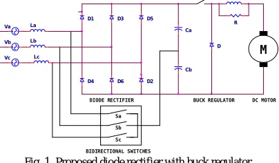
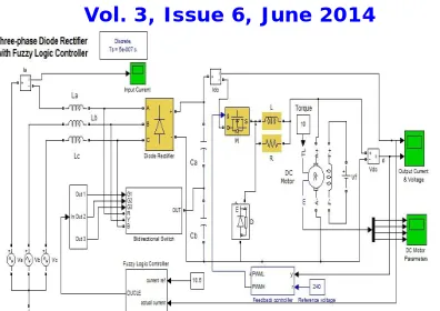
The circuit diagram of proposed diode rectifier with buck regulator is shown in Fig. 1. For the circuit analysis, six topological stages are presented in Fig. 2 a to f, corresponding to the 0° to 180° half period. Two main situations can be identified:
Va
D1
DC MOTOR
R D3
Sc
Cb
BIDIRECTIONAL SWITCHES Sb
D6
Sa
L
D4
Ca
DIODE RECTIFIER BUCK REGULATOR M
Lc Lb La
D2 Vb
D D5
Vc
Fig. 1. Proposed diode rectifier with buck regulator
1. In the stage I, III and V, there are only two conducting diodes. As a result, on a conventional three-phase rectifier, the current on the third phase remains null during that interval. In the circuit, the switch associated with the third phase is gated on during that interval. For instance, during the 0° to 30° stage, the bidirectional switch is gated on, so the input current evolves from zero to a maximum value.
2. In the stage II, IV and VI, there are three conducting diodes, one associated with each phase. The three switches are off, so the converter behaves like a conventional rectifier with input inductors.
Vc
1 2
D5
Lb Vb
1 2
Ca
Lc
R La
D6 Cb
Va
1 2
(a)
(b)
Vol. 3, Issue 6, June 2014
(d)
(e)
D2 La
Lc
Cb Va
1 2 Ca
R Vb
1 2 Lb
D3 D1
Vc
1 2
(f)
Fig. 2. Conduction of diodes of six topological stages
(a) Stage I – 0°to30° (b) Stage II– 30°to60° (c) Stage III – 60° to 90° (d) Stage IV – 90° to 120° (e) Stage V – 120°to150° (f) Stage I – 150°to180°
A. Bidirectional Switches
When gate circuit is open and Vdd is present, no current flow from drain to source. When gate terminal is made positive with respect to source, current flows from drain to source. The construction of bidirectional switch using four diodes and MOSFET is shown in Fig. 3.
Da
1
3
2
Dd
Dc
Db
Fig. 3. Bidirectional switch
During positive half cycle of the input voltage, diodes Da and Db are forward biased. When gate signal is applied with respect to source, the input current flows through Da, MOSFET and Db to the load.
During negative half cycle of the input voltage, diodes Dc and Dd are forward biased. When gate signal is applied with respect to source, the input current flows through Dc, MOSFET and Dd to the load.
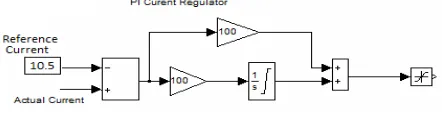
B. PI Current Controller
Fig. 4 shows the block diagram of PI current controller. It continuously compares the output current with the reference value and generates the signal to control the conduction of the bidirectional switch. The summing point produces the error signal by comparing the output current and reference value. This error signal is given to the integrator through the gain block to Continuous-time integration of the input signal. The output the integrator and error signal is given to another summing point. The output of summing point is given to the saturation block to limit the input signal to the upper and lower saturation values.
Vol. 3, Issue 6, June 2014
C. Fuzzy Logic Controller
The inputs to the fuzzy controller are output current and Error (e) in output current. The output from the fuzzy controller is control signal CS. The fuzzy variables Negative Large (NL), Negative Medium (NM), Negative Small (NS), Zero (Z), Positive Large (PL), Positive Medium (PM) and Positive Small (PS). In the simple block diagram of the Fuzzy Logic control system shown in Fig. 5, the reference current is compared with a output current of diode rectifier, and the difference between the reference current and output current is equal to the error (e). The output current and error are both uses as inputs to the FL controller. The FL controller uses the TSK technique to obtain control signal as its output. The control signal is then fed to the bidirectional switches to modify the conduction period and then input current.
Fig. 5. Fuzzy Controller
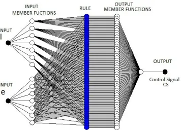
D. Adaptive Neuro-Fuzzy Inference Systems (ANFIS)
The objective is to design Adaptive Neuro-Fuzzy Inference Systems (ANFIS) that will improve the input current total harmonic distortion (THD) as well as power factor at the input stage by controlling the conduction period of the bidirectional switches. The ANFIS will use both the output current and output current error of the circuit as input and obtain a control signal as its output. The controls signal will then increase or decrease the conduction period of bidirectional switches that will either achieve the desired power factor at the input stage. The ANFIS Model Structure is shown in Fig. 6.
Vol. 3, Issue 6, June 2014
III. SIMULATIONRESULTS
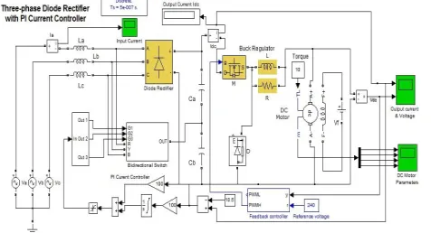
The closed loop simulation diagram of three phase diode rectifier with bidirectional switch is shown in Fig. 7.
Fig. 7. Closed loop control of three phase diode rectifier with bidirectional switch
The input current waveform and THD of three phase diode rectifier with bi directional switch is shown in Fig. 8. The THD value of input current is 24.94 %.
Fig. 8. The input current waveform and THD of three phase diode rectifier with bidirectional switch for closed loop control
The load test on DC motor with closed loop control was performed and reading was tabulated in the table. III. In this closed control, input current value is increased and therefore input power is also increases gradually. So the performance of the DC motor is improved.
TABLE ILOAD TEST ON THREE PHASE DCMOTOR WITH CLOSED LOOP CONTROL
The Fuzzy Logic Controller based simulation diagram of three phase diode rectifier is shown in Fig. 9. The input current waveform and THD of three phase diode rectifier with bidirectional switch is shown in Fig. 10. The THD value of input current is improved with 24.20 % when compared with closed loop system of 24.94 %. So the input current waveform is also improved with sinusoidal form.
Torque (N-m)
Input Current (Amps)
Input Voltage (Volts)
Speed (RPM)
Input Power (Watts)
Output Power
(Watts) Effi. (%)
1 2.4 223 1730 535.20 181.07 33.83
2 3.1 221 1711 685.10 358.17 52.28
3 4.1 217 1697 889.70 532.86 59.89
4 5 214 1685 1070.00 705.45 65.93
5 6.2 212 1674 1314.40 876.06 66.65
6 7.4 210 1664 1554.00 1044.9 67.25
7 8.5 208 1655 1768.00 1212.5 68.58
8 9.4 206 1647 1936.40 1379.0 71.22
9 9.9 204 1642 2019.60 1546.7 76.59
Vol. 3, Issue 6, June 2014
Fig. 9. Fuzzy Logic Controller based simulation diagram of three phase diode rectifier
Fig. 10. The input current waveform and THD of three phase diode rectifier with bi directional switch for fuzzy logic control
The load test on DC motor with fuzzy logic control was performed and reading was tabulated in the table. II. In this fuzzy logic control, input current value is further increased when compared with closed loop control and therefore input power is also increases gradually. So the performance of the DC motor is improved.
TABLE II LOAD TEST ON THREE PHASE DCMOTOR WITH FUZZY LOGIC CONTROL
The Adaptive Neuro-Fuzzy Inference Systems (ANFIS) based simulation diagram of three phase diode rectifier with bi directional switch is shown in Fig. 11.
Torque (N-m)
Input Current (Amps)
Input Voltage (Volts)
Speed (RPM)
Input Power (Watts)
Output Power
(Watts) Effi. (%)
1 2.6 218 1756 566.80 183.79 32.43
2 3.2 214 1749 684.80 366.12 53.46
3 4.2 212 1737 890.40 545.42 61.26
4 5.1 210 1726 1071.0 722.62 67.47
5 6.3 209 1719 1316.7 899.61 68.32
6 7.5 207 1707 1552.5 1072.00 69.05
7 8.6 206 1692 1771.6 1239.67 69.97
8 9.5 205 1684 1947.5 1410.07 72.40
9 10.1 203 1672 2050.3 1575.02 76.82
Vol. 3, Issue 6, June 2014
Fig. 11. Adaptive Neuro-Fuzzy Inference Systems based simulation diagram of three phase diode rectifier
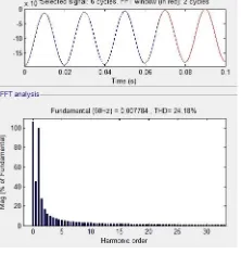
The input current waveform and THD of three phase diode rectifier with bi directional switch is shown in Fig. 12. The THD value of input current is improved with 24.18 % when compared with closed loop system of 24.94 %. So the input current waveform is also improved with sinusoidal form.
Fig. 12. The input current waveform and THD of three phase diode rectifier with bi directional switch for fuzzy logic control
The load test on DC motor with Adaptive Neuro-Fuzzy Inference Systems (ANFIS) was performed and reading was tabulated in the table. III. In this system, input current value is further increased when compared with closed loop control and therefore input power is also increases gradually. So the performance of the DC motor is improved.
TABLE IIILOAD TEST ON THREE PHASE DCMOTOR WITH ADAPTIVE NEURO-FUZZY INFERENCE SYSTEMS (ANFIS)
The relationship between torque and efficiency for closed loop control, Fuzzy control and Adaptive Neuro-Fuzzy Inference Systems (ANFIS) is shown in Fig. 13. The efficiency of the DC motor is improved in the Adaptive Neuro-Fuzzy Inference Systems (ANFIS). The comparision of simulation results are shown in Table. IV.
Torque (N-m)
Input Current (Amps)
Input Voltage (Volts)
Speed (RPM)
Input Power (Watts)
Output Power (Watts)
Effi. (%)
1 2.6 212 1758 551.20 184.00 33.38
2 3.2 210 1752 672.00 366.75 54.58
3 4.3 207 1742 890.10 546.99 61.45
4 5.3 203 1736 1075.90 726.81 67.55
5 6.5 202 1724 1313.00 902.23 68.71
6 7.6 202 1712 1535.20 1075.14 70.03
7 8.7 202 1699 1757.40 1244.80 70.83
8 9.6 196 1689 1881.60 1414.26 75.16
9 10.3 193 1683 1987.90 1585.39 79.75
Vol. 3, Issue 6, June 2014
Torque Vs Efficiency
0 10 20 30 40 50 60 70 80 90 100
1 2 3 4 5 6 7 8 9 10
Torque E ff ic ie n c y PI Controller Fuzzy Controller ANFIS Controller
Fig. 13. Variation of efficiency with torque
TABLE IVCOMPARISON OF SIMULATION RESULTS
Controller Max. Efficiency Without Filter at Torque 10 N-m (%) Improvement in Efficiency (%)
PI Current Controller 82.8 3
Fuzzy Logic Controller 83.57 4
ANFIS 85.78 6.5
IV. CONCLUSION
From the results it is evident that three phase diode rectifier with PI controller, Fuzzy Inference System and Adaptive Neuro-Fuzzy Inference Systems have improved performance in terms of input current harmonics distortion (THD), power factor at input and output side, voltage regulation and switching losses. Good performance is exhibited in recognizing the optimal generation of control signal to the bidirectional switches. The technique has been tested for the three phase diode rectifier with various load torque condition of DC motor. The network is trained by different possible combinations of the output current and its corresponding optimal signal is generated for triggering of bidirectional switches. The test results were compared for ANFIS with FLC. The FLC with neural network makes the solution little bit more efficient only by trains the parameters.
REFERENCES
[1]. S. M. Halpin, “Comparison of IEEE and IEC harmonic standards,” in Proc. IEEE Power Eng. Soc. Gen. Meeting, Jun. 2005, pp. 2214–2216.
[2]. T. Thasananutariya and S. Chatratana, “Planning study of harmonic filter for ASDs in industrial facilities,” IEEE Trans. Ind. Appl., vol. 45, no.
1, pp. 295–302, Jan./Feb. 2009.
[3]. Z. Chen and Y. Luo, “Low-harmonic-input three-phase rectifier with passive auxiliary circuit: Comparison and design consideration,” IEEE Trans. Ind. Electron., vol. 58, no. 6, pp. 2265–2273, Jun. 2011.
[4]. P. J. Grbovic, P. Delarue, and P. L. Moigne, “A novel three-phase diode boost rectifier using hybrid half-dc-bus-voltage rated boost converter,”
IEEE Trans. Ind. Electron., vol. 58, no. 4, pp. 1316–1329, Apr. 2011.
[5]. V. Corasaniti, M. Barbieri, P. Arnera, and M. Valla, “Hybrid active filter for reactive and harmonics compensation in a distribution network,”
IEEE Trans. Ind. Electron., vol. 56, no. 3, pp. 670–677, Mar. 2009.
[6]. B. Singh and J. Solanki, “Implementation of an adaptive control algorithm for a three-phase shunt active filter,” IEEE Trans. Ind. Electron., vol.
56, no. 8, pp. 2811–2820, Aug. 2009.
[7]. E. Lavopa, P. Zanchetta, M. Sumner, and F. Cupertino, “Real-time estimation of fundamental frequency and harmonics for active shunt power
filters in aircraft electrical systems,” IEEE Trans. Ind. Electron., vol. 56, no. 8, pp. 2875–2884, Aug. 2009.
[8]. S. Rahmani, N. Mendalek, and K. Al-Haddad, “Experimental design of a nonlinear control technique for three-phase shunt active power filter,”
IEEE Trans. Ind. Electron., vol. 57, no. 10, pp. 3364–3375, Oct. 2010.
[9]. O. Vodyakho and C. Mi, “Three-level inverter-based shunt active power filter in three-phase three-wire and four-wire systems,” IEEE Trans.
Power Electron., vol. 24, no. 5, pp. 1350–1363, May 2009.
[10].P. Salmeron and S. P. Litran, “Improvement of the electric power quality using series active and shunt passive filters,” IEEE Trans. Power Del.,
vol. 25, no. 2, pp. 1058–1067, Apr. 2010.
[11].Bhattacharya and C. Chakraborty, “A shunt active power filter with enhanced performance using ANN-based predictive and adaptive
controllers,” IEEE Trans. Ind. Electron., vol. 58, no. 2, pp. 421–428, Feb. 2011.
[12].Gensior, H. Sira-Ramirez, J. Rudolph, and H. Guldner, “On some nonlinear current controllers for three-phase boost rectifiers,” IEEE Trans.
Ind. Electron., vol. 56, no. 2, pp. 360–370, Feb. 2009.
[13].M. H. Bierhoff and F. W. Fuchs, “Active damping for three-phase PWM rectifiers with high-order line-side filters,” IEEE Trans. Ind. Electron.,
vol. 56, no. 2, pp. 371–379, Feb. 2009.
[14].M. L. Heldwein and J. W. Kolar, “Impact of EMC filters on the power density of modern three-phase PWM converters,” IEEE Trans. Power
Vol. 3, Issue 6, June 2014
[15].D. Carlton, W. Dunford, and M. Edmunds, “Harmonic reduction in the 3-phase 3-switches boost-delta power factor correction circuit operating
in discontinuous conduction mode,” in Proc. 20th Int. Telecommun. Energy Conf., Oct. 1998, pp. 483–490.
[16].L. Dalessandro, S. D. Round, U. Drofenik, and J. W. Kolar, “Discontinuous space-vector modulation for three-level PWMrectifiers,” IEEE Trans. Power Electron., vol. 23, no. 2, pp. 530–542, Mar. 2008.
[17].F. J. Chivite-Zabalza, A. J. Forsyth, and I. Araujo-Vargas, “36-Pulse hybrid ripple injection for high-performance aerospace rectifiers,” IEEE
Trans. Ind. Appl., vol. 45, no. 3, pp. 992–999, May/Jun. 2009.
[18].le Roux, H. Mouton, and H. Akagi, “DFT-based repetitive control of a series active filter integrated with a 12-pulse diode rectifier,” IEEE Trans. Power Electron., vol. 24, no. 6, pp. 1515–1521, Jun. 2009.
[19].J. C. Salmon, “Reliable 3-phase PWM boost rectifiers employing a stacked dual boost converter subtopology,” IEEE Trans. Ind. Appl., vol. 32,
no. 3, pp. 542–551, May/Jun. 1996.
[20].Qiao and K. M. Smedley, “A general three-phase PFC controller for rectifiers with a series-connected dual-boost topology,” IEEE Trans. Ind.
Appl., vol. 38, no. 1, pp. 137–148, Jan./Feb. 2002.
[21].N. Mohan, “A novel approach to minimize line-current harmonics in interfacing power electronics equipment with 3-phase utility systems,” IEEE Trans. Power Del., vol. 8, no. 3, pp. 1395–1401, Jul. 1993.
[22].R. Naik, M. Rastogi, and N. Mohan, “Third-harmonic modulated power electronics interface with three-phase utility to provide a regulated dc
output and to minimize line-current harmonics,” IEEE Trans. Ind. Appl., vol. 31, no. 3, pp. 598–602, May/Jun. 1995.
[23].S. Kim, P. N. Enjeti, P. Packebush, and I. J. Pital, “A new approach to improve power factor and reduce harmonics in a three-phase diode rectifier type utility interface,” IEEE Trans. Ind. Appl., vol. 30, no. 6, pp. 1557–1564, Nov./Dec. 1994.
[24].P. Pejovic and Z. Janda, “An analysis of three-phase low-harmonic rectifiers applying the third-harmonic current injection,” IEEE Trans. Power
Electron., vol. 14, no. 3, pp. 397–407, Mar. 1999.
[25].P. Pejovic and Z. Janda, “An improved current injection network for three-phase high-power-factor rectifiers apply the third harmonic current
injection,” IEEE Trans. Ind. Electron., vol. 47, no. 2, pp. 497–499, Apr. 2000.
[26].J.-I. Itoh and I. Ashida, “A novel three-phase PFC rectifier using a harmonic current injection method,” IEEE Trans. Power Electron., vol. 23,
no. 2, pp. 715–722, Mar. 2008.
[27].G. T. Sundar Rajan and C. Christober Asir Rajan, “A Novel Unity Power Factor Input Stage With Resonant DC Link Inverter for AC Drives”,
Journal of Electrical Engineering, Volume 12 / 2012 - Edition: 4, pp. 62 – 66, 2012.
[28].G. T. Sundar Rajan and C. Christober Asir Rajan, “Fuzzy Inference System Based Power Factor Correction of Three Phase Diode Rectifier using Field Programmable Gate Array”, American Journal of Applied Sciences, Volume 10 - Issue 9 / 2013, pp. 986-999.
[29].G. T. Sundar Rajan and C. Christober Asir Rajan, “Input stage improved power factor of three phase diode rectifier using hybrid unidirectional
rectifier”, in Proc. IEEE conf. on Nanoscience, Engineering and Technology – ICONSET – 2011, Sathyabama Uiversity, pp. 697 – 682, November 28 to 30, Chennai.
[30].G. T. Sundar Rajan and C. Christober Asir Rajan, “Closed loop control of diode rectifier with power factor correction at input stage for DC drive application” 3rd International Conference on Electrical, Computer, Electronics & Biomedical Engineering (ICECEBE'2013), pp. 180 – 184, April 29-30, 2013 Singapore
BIOGRAPHY
G. T. Sundar Rajanwas born in 1975. He has received the B.E. (Electrical and Electronics) degree from the Madras University