5
MANAGING AND MODELLING OF
3D SPATIAL OBJECTS FOR URBAN
ENVIROMENT
Siti Nur Awanis Mohamad Zulkifli
Alias Abdul Rahman
Department of Geoinformatics,
Faculty of Geoinformation Science and Engineering, Universiti Teknologi Malaysia, 81310 UTM Skudai, Johor,
Malaysia.
ABSTRACT
Managing and Modeling of 3D Spatial Objects for Urban Environment 87 software. A 3D case study performed by using Oracle Spatial and MicroStation Bentley Map provides some knowledge on the 3D functionality offered by commercial systems. At the end, the paper addresses some of the issues and problems involved in developing such a system and recommends directions for further research.
1.0 INTRODUCTION
focusing on the modeling and management of complex 3D objects – in a primarily relational DBMS environment, e.g. (Pfund, 2001 and Wang, 2000). Some ongoing projects employ object-relational concepts to address the issues of topology (Oosterom et al., 2002) and integrated 3D geodata management within a 3D GIS framework, e.g. (Nebiker, 2002a, and Zlatanova et al., 2002). Therefore, in this paper we highlighted all the experiment to manage and modelling 3D spatial objects using Oracle Spatial and Bentley Map. Section 2 elaborates the method on how to represent the 2D and 3D spatial objects in the DBMS. In section 3, the experiment on managing the 3D spatial objects are highlighted. Finally, section 4 concludes all the current work.
2.0 MODELLING THE REAL WORLD OBJECTS
Managing and Modeling of 3D Spatial Objects for Urban Environment 89
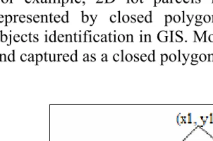
In general, 2D objects could be represented by a series of polygon geometry, and their nodes as list of points i.e. connected one-by-one by straight line segments and the last point connected to the first.
For example, 2D lot parcels in 2D DBMS are mostly represented by closed polygons, as this will simplify objects identification in GIS. Most lot parcels are identified and captured as a closed polygon as shown at figure 1.
90 Advances toward 3D GIS
The representation of real world objects is far more complicated when we move to 3D application. In 3D, opposed to 2.5D, it is not possible to assume that objects can be flattened and defined as polygon footprint on the surface. Instead, a proper 3D model representation of the object is needed, meaning more than one Z-value is attached to a 2D polygon and more information is needed than one Z-value attached to the vertices of the 2D polygon (Zlatanova, 2000).
In 3D, the definition of the geometrical and topological description and validation of the correctness is far more complicated than in 2D. The polyhedral approach, as described in among others (Stoter, 2004) defines the polygons, where each polygon should be ‘flat’ and valid according to the Simple Feature Specification (SFS) of the Open Geospatial Consortium (OGC), i.e. non-self intersecting. The set of faces should enclose a single volume.
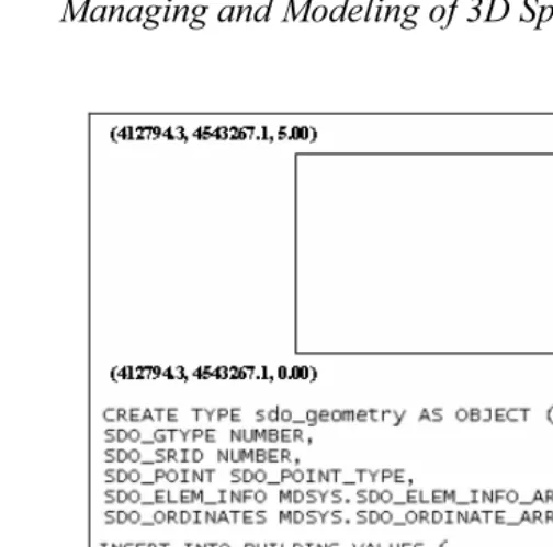
For example, in this research Oracle Spatial 10g are used to manage 3D points, lines and polygons. Using 3D polygons, 3D spatial objects can be represented as polyhedron in two methods:
face-by-face polygons. multipolygon collection.
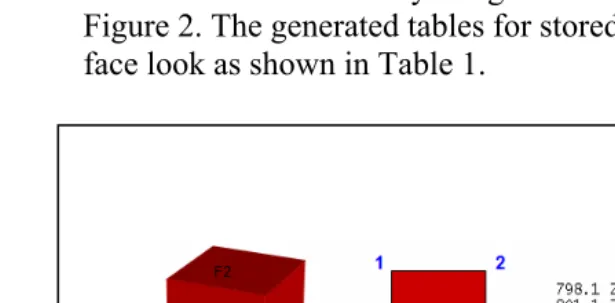
In the first method, 3D objects are defined as face-by-face polygons. This model is partly a topological model; since the body is defined by references to the faces (faces share two bodies). To develop 3D objects, series of coordinates that contain x, y, z are extracted from one face of object to another face of object. The 3D object was stored as a list of 3D polygon and it defined by reference to the faces and the
Managing and Modeling of 3D Spatial Objects for Urban Environment 91 faces can be shared by neighbour-bodies as shown at Figure 2. The generated tables for stored 3D object face-by-face look as shown in Table 1.
Figure 2: The extracted coordinates (face by face) of the 3D object, (a) Build_ID: 1, (b) Face_ID: 1, (c) list of coordinate for
face 1.
Table 1: Coordinates list face by face
Build_ID Face_ID Shape(mdsys.sdo_geometry)
1 1 x1,y1,z1 x3,y3,z3 x4,y4,z4 x2,y2,z2 x1,y1,z1 2 x7,y7,z7 x1,y1,z1 x2,y2,z2
x5,y5,z5 x7,y7,z7 3 x2,y2,z2 x4,y4,z4 x6,y6,z6
x5,y5,z5 x2,y2,z2 4 x7,y7,z7 x8,y8,z8 x6,y6,z6
z5,y5,z5 x7,y7,z7
5 x1,y1,z1 x3,y3,z3 x8,y8,z8 z7,y7,z7 x1,y1,z1 6 x8,y8,z8 x3,y3,z3 x4,y4,z4
z6,y6,z6 x8,y8,z8
An advantage of face by face polygons is that it is recognized as one object by front-end applications (GIS/CAD) that can access, visualize, and edit these data and post the changes back to the database so we can easily store the information about the object i.e. face 1 represent the wall and face 2 represent the roof.
Managing and Modeling of 3D Spatial Objects for Urban Environment 93
Figure 3: Representation of 3D object using multipolygon method.
3.0 MANAGING 3D SPATIAL OBJECTS
Over the last few years we have seen an increasing amount of work in the field of modeling and managing geospatial 3D objects. A number of projects were focusing on the modeling and management of 3D objects.
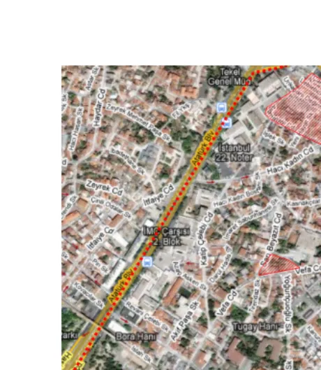
3.1 Study Area
Managing and Modeling of 3D Spatial Objects for Urban Environment 95
3.2 The conceptual data model
Managing and Modeling of 3D Spatial Objects for Urban Environment 97
In this model, the 3D objects were represented by BODY_BUILDING and BUILDING tables. All of these tables contain geometry and attributes of the objects.
The attribute components for the 3D objects No_Lot: number of lot parcel
Build_Name: name of the building Build_ID: Id of the building Age: age of the building Face_ID: Id of the faces
Material: Material of the faces e.g. brick, concrete Description: Description of the faces e.g. wall, roof
The geometry components for the 3D objects Polygon: include the geometry of the object
The components of 2D objects consist of LOT, PARCELLER and ROAD. The attributes and geometry for 2D objects components are as follows:
The attributes for 2D objects
No_Lot: number of lot parcel Lot_Perimeter: perimeter of the lot Lot_Area: area of lot
Managing and Modeling of 3D Spatial Objects for Urban Environment 99 Type: type of the road e.g. highway
The geometry component for 2D objects
Polygon: include the geometry of the object
3.3 The logical model
Table 2: Description of BODY_BUILDING and BUILDING table.
3.4 Storingof3DobjectusingfaceǦbyǦface method
Managing and Modeling of 3D Spatial Objects for Urban Environment 101
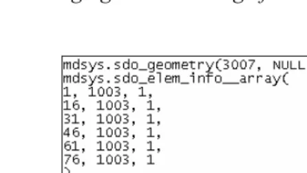
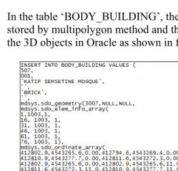
3.5 Storingof3Dobjectusingmultipolygon method
In the table ‘BODY_BUILDING’, the 3D objects are stored by multipolygon method and the example to store the 3D objects in Oracle as shown in figure 7.
Managing and Modeling of 3D Spatial Objects for Urban Environment 103 3.6 Managing 2D and 3D spatial object in DBMS
In managing 2D and 3D spatial object, Oracle Spatial supports storage for 3D points, lines and polygons. In this experiment, we divide into four steps to store spatial object in DBMS. The first step is creating 2D and 3D tables. In this case, we choose the table ‘LOT’ to represent 2D objects and the table “BUILDING’ to represent 3D objects. The steps to create table for spatial objects as shown in Figure 8.
The next steps are inserting the dataset. In Figure 9 represent the SQL- how to insert the 2D and 3D datasets.
Managing and Modeling of 3D Spatial Objects for Urban Environment 105 The third step is inserting the metadata. Besides the tables that represent the geometries of the objects, metadata is maintained in Oracle by describing the dimension, lower and upper bounds and tolerance in each dimension. In the following figure (Figure 10), the information on the tables (LOT and BUILDING) is inserted in the metadata table. The final step, a spatial index (r-tree in 2D and in 3D) is created in the tables (to speed up spatial queries) as shown in Figure 11.
Figure 11: Step 4 - Creating Index.
3.7 The Linkage between Oracle Spatial and Bentley Map
Bentley Map is directly integrated with MicroStation and takes advantage of its features i.e. capture, editing, display, and output capabilities. It supported geospatial modelling and interoperability. It also capable to import n export to ESRI SHP files, MapInfo TAB files, Oracle Spatial features and others.
In Bentley Map, topological relationships are stored in the DGN file according to the same model employed by Oracle Spatial. This allows complex analysis operations to occur quickly and maintains compatibility with Oracle Spatial for organizations that choose to use Bentley Map as an editing application for Oracle Spatial.
Managing and Modeling of 3D Spatial Objects for Urban Environment 107 and shows the 2D objects and 3D objects were upload into the Bentley Map.
3.8 Editing 3D objects in Bentley Map
In Bentley Map, we also can edit the spatial objects using the EDIT function. After editing, we can post the new object directly to Oracle database as shown in the figure 13.
Managing and Modeling of 3D Spatial Objects for Urban Environment 109 Beside that, we also can change texture of the object. Figure 14 show how the 3D wire frame objects we transform into the solid texture, Figure 15 texture the object using the generated texture and Figure 16 show the 3D objects with the real texture.
Managing and Modeling of 3D Spatial Objects for Urban Environment 111
Figure 16: 3D objects with real texture
3.9 Query of objects in Bentley Map
In Bentley Map, the query is conducted via the visual SQL Query Builder features. Figure 17 shows the list of spatial attributes based on the selected table. The query for faces registration is conducted by selecting the faces attributes. The output of the experiment can be seen in figure 18. The same method is also applied for querying multi polygon registration. Figure 19 shows the result of the query.
Managing and Modeling of 3D Spatial Objects for Urban Environment 113
Figure 18: The result of the spatial query based on face-by-face method
4.0 CONCLUDING REMARKS
In this paper, we have discussed how to manage 3D spatial objects on Oracle Spatial 10g and visualize in Bentley Map and exhibited valuable information related to 3D functionality (query based on 3D objects selection, editing 3D spatial objects and attributes) currently offered. In addition visualising 3D objects stored in a DBMS is not always straightforward. With Bentley Map it is possible to visualise 3D objects rather easily, however the posting of data to the DBMS is not straight forward. The user is expected to have excellent skills in both systems, i.e. understanding the conceptual representation in Bentley Map and being aware of the implementation in storing geometrical and topological data in Oracle Spatial 10g. In the future, we would like to extend the work by addressing the automated spatial data updating and maintenance.
REFERENCES
Arens, C., J.E. Stoter, and P.J.M. van Oosterom (2003), Modelling 3D spatial objects in a GeoDBMS using a 3D primitive, under review for AGILE 2003.
Managing and Modeling of 3D Spatial Objects for Urban Environment 115 Batty M, Dodge M, Jiang B, Smith A, 1998, GIS and
Urban Design, ISSN:1467-1298 CASA, UCL, http://www.casa.ucl.ac.uk/urbandesifinal.pdf.
Bentley (2002), Bentley Map edition (2007). URL: http://www.bentley.com/products/bentley-map/
De La Losa, 1998, Toward a 3D GIS: Conception of a 3D GIS with a complete topological management, In: Proceedings of GIS PlaNET’98 Conference, Lisbon, Portugal
ESRI, 1997, Using ArcView 3D Analyst. ESRI Publication, Redlands, California, USA, 118. p.
Oosterom, P. v, J. Stoter, W. Quak and S. Zlatanova, 2002, The balance between geometry and topology, In: Proceedings of Spatial Data Handling, 8-12 July, Ottawa, Canada (to be published)
Oracle (2001): Oracle Spatial User's Guide and Reference Release 9.0.1 Part Number A88805-01, June 2001. Stoter, J. and P. van Oosterom, 2002, Incorporating 3D
geoobjects into a 2D geo-DBMS, Proceedings of SPRS/ACSM, 19-26 April, 2002, Washington, USA. Varshosaz M., 2003. True Realistic 3d Models Of
Buildings In Urban Areas, International Archives of the Photogrammetry, Remote Sensing and Spatial Information Sciences, Vol. XXXIV-5/W10.
Zlatanova, S., 2000, 3D GIS for urban development, PhD thesis, ITC, The Netherlands, 222 p.