University of Windsor University of Windsor
Scholarship at UWindsor
Scholarship at UWindsor
Electronic Theses and Dissertations Theses, Dissertations, and Major Papers
2009
Wind Tunnel Study on the Aerodynamic Performance of
Wind Tunnel Study on the Aerodynamic Performance of
Deflectors with Different Shapes
Deflectors with Different Shapes
Yaoyao Zhang University of Windsor
Follow this and additional works at: https://scholar.uwindsor.ca/etd
Recommended Citation Recommended Citation
Zhang, Yaoyao, "Wind Tunnel Study on the Aerodynamic Performance of Deflectors with Different Shapes" (2009). Electronic Theses and Dissertations. 8254.
https://scholar.uwindsor.ca/etd/8254
This online database contains the full-text of PhD dissertations and Masters’ theses of University of Windsor students from 1954 forward. These documents are made available for personal study and research purposes only, in accordance with the Canadian Copyright Act and the Creative Commons license—CC BY-NC-ND (Attribution, Non-Commercial, No Derivative Works). Under this license, works must always be attributed to the copyright holder (original author), cannot be used for any commercial purposes, and may not be altered. Any other use would require the permission of the copyright holder. Students may inquire about withdrawing their dissertation and/or thesis from this database. For additional inquiries, please contact the repository administrator via email
Wind Tunnel Study on the Aerodynamic
Performance of Deflectors with Different Shapes
By
Yaoyao Zhang
A Thesis
Submitted to the Faculty of Graduate Studies through the Department of Mechanical,
Automotive and Materials Engineering in Partial Fulfillment of the Requirements for the
Degree of Master of Applied Science at the University of Windsor
Windsor, Ontario, Canada
2009
1*1
Library and Archives CanadaPublished Heritage Branch
395 Wellington Street Ottawa ON K1A 0N4 Canada
Bibliotheque et Archives Canada
Direction du
Patrimoine de I'edition
395, rue Wellington Ottawa ON K1A 0N4 Canada
Your file Votre reference ISBN: 978-0-494-82091-9 Our file Notre reference ISBN: 978-0-494-82091-9
NOTICE:
The author has granted a
non-exclusive license allowing Library and Archives Canada to reproduce, publish, archive, preserve, conserve, communicate to the public by
telecommunication or on the Internet, loan, distribute and sell theses
worldwide, for commercial or non-commercial purposes, in microform, paper, electronic and/or any other formats.
AVIS:
Lauteur a accorde une licence non exclusive permettant a la Bibliotheque et Archives Canada de reproduire, publier, archiver, sauvegarder, conserver, transmettre au public par telecommunication ou par I'lnternet, preter, distribuer et vendre des theses partout dans le monde, a des fins commerciales ou autres, sur support microforme, papier, electronique et/ou autres formats.
The author retains copyright ownership and moral rights in this thesis. Neither the thesis nor substantial extracts from it may be printed or otherwise reproduced without the author's permission.
Lauteur conserve la propriete du droit d'auteur et des droits moraux qui protege cette these. Ni la these ni des extra its substantiels de celle-ci ne doivent etre imprimes ou autrement
reproduits sans son autorisation.
In compliance with the Canadian Privacy Act some supporting forms may have been removed from this thesis.
While these forms may be included in the document page count, their removal does not represent any loss of content from the thesis.
Conformement a la loi canadienne sur la protection de la vie privee, quelques formulaires secondaires ont ete enleves de cette these.
Bien que ces formulaires aient inclus dans la pagination, il n'y aura aucun contenu manquant.
• • I
AUTHOR'S DECLARATION OF ORIGINALITY
I am aware of the University of Windsor Senate Policy on Authorship and I
certify that I have properly acknowledged the contribution of other researchers to my
thesis, and have obtained written permission from each of the co-author(s) to include the
above material(s) in my thesis.
I certify that, with the above qualification, this thesis, and the research to which it
refers, is the product of my own work.
I declare that, to the best of my knowledge, my thesis does not infringe upon
anyone's copyright nor violate any proprietary rights and that any ideas, techniques,
quotations, or any other material from the work of other people included in my thesis,
published or otherwise, are fully acknowledged in accordance with the standard
referencing practices. Furthermore, to the extent that I have included copyrighted
material that surpasses the bounds of fair dealing within the meaning of the Canada
Copyright Act, I certify that I have obtained a written permission from the copyright
owner(s) to include such material(s) in my thesis.
I declare that this is a true copy of my thesis, including any final revisions, as
approved by my thesis committee and the Graduate Studies office, and that this thesis has
not been submitted for a higher degree to any other University of Institution.
ABSTRACT
The continuously increasing gasoline and diesel fuel costs generated immense
interest in road vehicle efficiency. Because the aerodynamic drag of road vehicles is a
major contributor to the fuel consumption at highway speeds, renewed interests ar e
focusing on attempts to find novel drag-reducing technology
In this project, a newly designed air deflector with the shape of three concave
surfaces was proposed. The effect of the deflector shape on the aerodynamic performance of a truck model, such as drag coefficient, was investigated. The results were compared
to the same truck model with conventional convex deflector and without deflector. The relationship between the deflector shape and the drag force coefficient, as well as
Reynolds number was revealed in all cases. The impact of deflector details on the
ACKNOWLEDGEMENTS
I would like to express my sincere gratitude to Dr. Shaohong Cheng and Dr. David S-K Ting for their invaluable supervision, patience, encouragement and guidance
throughout this research. Sincere thanks are also expressed to the committee members:
Dr. D. Green and Dr. A. Edrisy for their helpful comments, suggestions and their
valuable time.
Technical assistance from the staff of the University of Windsor Technical Support
Centre is appreciated, especially to Mr. Andrew Jenner and Mr. Patrick Seguin.
The financial support from the Natural Sciences and Engineering Research Council of Canada in the form of Research Assistantship and an Equipment Grant are gratefully
acknowledged. The financial support from the Department of Mechanical, Automotive and Materials Engineering in the form of a Graduate Assistantship is also acknowledged.
The author appreciates the grateful support from her parents and her sister during this study.
TABLE OF CONTENTS
Author's Declaration of Originality — iii
Abstract iv
Acknowledgements v
List of Tables viii
List of Figures ix
Nomenclature — xiii
Chapter 1 INTRODUCTION — - 1
1.1 Project Background 1
1.2 Motivation — - 2
1.3 Objectives — 3
Chapter 2 LITERATURE REVIEW — 4
2.1 Aerodynamic Drag Reduction of Heavy Vehicles 4
2.2 Characteristics of Air Deflectors Mounted on Tractor-Trailers— 10
2.3 Application of Deflectors - — - 12
2.4 Wind Tunnel Testing - - 13
2.4.1 Reynolds Number Effect - - 14
2.4.2 Yaw Angle Effect -— 18
2.4.3 Turbulence Effect - - 18
2.5 Wake Structure of a Tractor-Trailer — — 19
Chapter 3 EXPERIMENTAL DETAILS - —23
3.1 Wind Tunnel - - -23
3.3 Hot-wire and Loadcell System- 28
3.4 Experimental Setup 29
Chapter 4 RESULTS AND DISCUSSIONS - 33
4.1 Tuft Flow Visualization - 33
4.2 Impact of Friction - 34
4.3 Drag Force Measurements 40
4.4 Impact of Yaw Angle — - 41
4.5 Wake Bubble - — 42
Chapter 5 CONCLUSIONS AND RECOMMENDATIONS 48
REFERENCES 51
APPENDIX A. Hotwire Anemometer 55
A.l Calibration Procedure Instruction and an Example 55
A.2 Matlab Program for ID-PROBE 61
A.3 Traverse Program 62
APPENDIX B. Load cell Calibration- - 69
APPENDIX C. Sampling Frequency/Number Selecting- 71
APPENDIX D. Uncertainty Analyses 72
APPENDIX E. Boundary Layer Effect - 75
APPENDIX F Blockage Ratio Effect - - 77
VITAAUCTORIS - - 79
LIST OF TABLES
Table 2.1 Increasing the effective Re by screen application 17 Table Dl Comparison of auto calibration and calibration with Pitot - static tube 72
LIST OF FIGURES
Figure 2.1 Graphic depicting the impact of aerodynamic uncertainty on horsepower
requirements for a heavy vehicle tractor-trailer truck [Wood and Bauer, 2003]
- - 4
Figure 2.2 Distribution of aerodynamic drag for a heavy vehicle tractor-trailer truck, with
and without aerodynamic fairings, operating in a zero crosswind condition
[Wood and Bauer, 2003] — 5
Figure 2.3 Sizing of roof-mounted plate for minimizing drag of tractor-trailer
combination [Mason and Beebe, 1978] 6
Figure 2.4 Optimum fairing for minimum drag when separated shear surface matched to
trailer leading edges [Mason and Beebe, 1978] 7
Figure 2.5 Sketch of the vortex strake trailer base treatment device installed on the aft
portion of the trailer [Wood and Bauer, 2003] 8 Figure 2.6 Air flow around a standard tractor -trailer without and with deflector
[Du et al, 2003] — - 10 Figure 2.7 Tractor-trailer configuration: add-on devices and body-details study
[Berta and Bonis, 1980] 11 Figure 2.8 Drag reductions through add-on devices with head-on airflow
[Hucho, 1998] — - - 12
Figure 2.9 Convex surface air deflector — — — 13 Figure 2.10 Other shape deflectors on the road - - — 13
Figure 2.11 Setup of road vehicle in the open test section [Wiedemann, 1989] 15 Figure 2.12 Pressure distribution on a road vehicle at different Re: no screen
[Wiedemann, 1989] - 16
Figure 2.13 Pressure distributions on a road vehicle at different Re: Turbulence modified
by a screen [Wiedemann, 1989] 16 Figure 2.14 Drag coefficient of a road vehicle without ground plane vs. Re 17
Figure 2.15 Drag reductions versus yaw angle through add-on devices
Figure 2.16 Horse shoe vortex system in the near wake region of an Ahmed body
[Yang, 2008] 20
Figure 2.17 General wake structures behind a blunt axisymmetric body
[Adapted from Duell 1993] - 20
Figure 2.18 Four models with different shapes: (a) Rectangular block (1:24) (b) Rounded
front model (1:24) (c) Generic model (1:24) (d) Scaled specific
model-Kenworth(l:24) [Yang, 2008] 21
Figure 2.19 Comparison of bubble shapes of all the truck models [Yang, 2008] 22
Figure 3.1 Closed-loop wind tunnel 23 Figure 3.2 Four different shape deflectors: (a) Convex surface deflector (b) Deflector
with 30 degree inclined flat surface (c) Deflector with 45 degree inclined flat
surface (d) Deflector with three concave surfaces 24
Figure 3.3 Dimensions of different deflectors: (a) 30 degree flat surface deflector
(b) 45 degree flat surface deflector (c) Proposed concave surface deflector~25
Figure 3.4 Side and front views of the 1:24 scale Kenworth truck model 26 Figure 3.5 Conventional deflector with convex surface - 27
Figure 3.6 Proposed concave surface deflector — 27
Figure 3.7 Truck model without deflector 28
Figure 3.8 Hot-wire system [CTA: Dantec Streamline® 55C90, I/O: shielded I/O
connector] 29
Figure 3.9 Experimental setup for drag force measurement - 30 Figure 3.10 Experimental arrangements for studying wake of the truck model 31
Figure 3.11 Grid for data collection — 32 Figure 4.1 Flow pattern around truck model when using different deflectors: (a) Flow
pattern on the top surface of trailer box when using conventional deflector (b) Flow pattern on the top surface of trailer box when using the proposed
deflector (c) Flow pattern on the top surface of trailer box when using inclined flat surface deflector (30 degree) (d) Flow pattern on the top surface of trailer box when using inclined flat surface deflector (45 degree) 34
Figure 4.2 Schematic of the experiment setup for drag force measurement on cylinder~35
Figure 4.4 Drag coefficients as a function of Reynolds number on friction testing 37
Figure 4.5 Experiment results compared to the standard curve 38
Figure 4.6 Impact of friction on drag measurement (conventional deflector) 39
Figure 4.7 Drag coefficients of model truck with different air deflectors under
smooth flow condition 40
Figure 4.8 Influence of Deflector Shape versus Yaw Angle (Re=6X 10⁵) 41
Figure 4.9 Near-wake time-averaged velocity distribution and recirculation length in each
horizontal line at the vertical central plane [Duell and George, 1993]
42
Figure 4.10 (a) Bubble shape of the truck model using original deflector in the wake at
Re=5xl05 43 Figure 4.10 (b) Bubble shape of the truck model using proposed deflector in the wake at
Re=5 x 10⁵ - 44
Figure 4.10 (c) Bubble shape of the truck model without deflector in the wake at
Re=5xl05 44
Figure 4.11 Wake bubble in the side plane by using the original deflector 46
Figure 4.12 Wake bubble in the side plane by using the proposed deflector 46
Figure 4.13 The sketch of a three-dimensional bubble- — 47
Figure Al Auto calibration: minimum velocity - - - 57 Figure A2 Auto calibration: maximum velocity - - 57
Figure A3 Results of auto calibration 58 Figure A4 Error of auto calibration — - 58
Figure A5 Default Setup - 59
Figure A6 Experiment layout — — 59
Figure A7 Temperature online analysis — 60 Figure Bl load cell calibration - — 69
Figure CI mean velocity vs. sampling number (x=l:l: sampling number) — 71
Figure El Velocity profiles 85 inch downstream the inlet of the wind tunnel
Boundary layer thickness (8=1.5 inch) - - - 75 Figure E2 Velocity profiles 55 inch downstream of the elevated plate leading edge 76
Figure Fl Definition of frontal area of a vehicle - - 77
NOMENCLATURE
A AN A/D D CDc
P CTA Fi F3 FD FD-TOP FD-BOTTOM Ff=uFn Fn F Total H I/O L Lplate t-'cyhnder N ReFrontal area of the vehicle
Cross-sectional area of wind tunnel testing section
Analogue/Digital
Diameter of the circular cylinder [m]
Drag coefficient, 2FD / p V2 A
Pressure coefficient
Constant Temperature Anemometer
Drag force in a top string [N]
Drag force in a bottom string [N]
Drag force, CD (p V2 A/2) [N]
Streamwise tensile component in a top string [N]
Streamwise tensile component in a bottom string [N]
Friction between the tires of truck model and the elevated
Normal force exerted between the surfaces
2FD-TOP+2FD-BOTTOM [N]
Height of the truck model [m]
Input/Output
Length of the truck model [m]
Length of the elevated plate [m]
Length of the circular cylinder [m]
Sampling number
T Thickness of the elevated plate [m]
T u Turbulence intensity ur m s/ U ( % )
Um Local m e a n velocity [m/s]
Uoo Free stream velocity [m/s]
U T i m e averaged velocity [m/s]
ums R o o t m e a n square velocity [m/s]
V M e a n flow velocity [m/s]
W W i d t h of the truck model [m]
Wpiate Width of the elevated plate [m]
X Distance between model base and d o w n s t r e a m Point for Velocity
measurement [m]
3-D Three-dimensional
Greek Symbols
a, a', P, P' Geometrical angle of cylinder setup
v Kinetic viscosity [m /s]
3n
p Density [kg/m ]
q> Blockage ratio
Chapter 1 INTRODUCTION
1.1 Project Background
On North American roads, truck population continues to grow in recent years. The large
amount of potential fuel saving coupled with increasing fuel cost has spurred renewed
interest in heavy-vehicle aerodynamics. From previous studies, it is known that
aerodynamic drag is a significant parasitic loss in a typical tractor-trailer system
operating at highway speed [Wood and Bauer, 2003]. For a typical heavy vehicle at a
highway speed of 1 OOkm/h, the energy required to overcome aerodynamic drag is about
65% of the total expenditure [Mason and Beebe, 1978]. Furthermore, data released by the
American Trucking Association indicated that the tractor/trailer interface contributes to
approximately 20% of the total drag. Therefore, practical devices to reduce aerodynamic
drag will offer a cost-effective opportunity to improve fuel economy.
Considerable efforts were made in the last few decades to study vehicle aerodynamics on
full-scale, on road study and reduced-scale wind tunnel testing [Vexler and Katz, 1985], as well as computational fluid dynamics (CFD) simulation [Patel and Vijayakumar, 2001]. The results show that aerodynamic performance can be improved by alerting the bodylines on a vehicle. Its drag coefficient can be maintained at a minimum value by
properly designing various component profiles [Hucho, 1998; Copper, 2003]. Based on those previous studies, tractor manufactures have made significant progress in reducing aerodynamic drag over the past three decades. Especially in recent years, research was focused on three areas within the tractor-trailer system: the tractor-trailer gap, trailer sides and trailer wake [Losito and Nicola, 1983]. A number of practical add-on devices to
reduce aerodynamic drag for tractor trailers were designed and applied in real life.
1.2 Motivation
Though trucks represent a significant fraction of the vehicles on the road, it is surprising
to note that the aerodynamic shape of the tractor-trailer, especially the tractor-mounted deflector, which is a critical drag-reduction facility, has remained largely unchanged
compared to the passenger automobile over the past few decades. Significant
opportunities remain to improve tractor-trailer aerodynamic integration and to offer
robust, practical aerodynamic solutions to customers.
Due to the utilitarian function of trucks, it is unlikely that it will experience significant
changes in the near future. However, this does not mean that trucks can not be improved in some manner that would be beneficial. The conventional air deflectors were based
primarily on streamlining the shape of the add-on devices on top of tractors, while the aerospace industry has gone through stages of development with ingenious features such
as winglets and grooves. Thus, it appears that new ideas may also be applied to air
deflector design. The information of how the details of vehicle shape would affect its aerodynamic performance, especially under different flow conditions, should be
1.3 Objectives
In this project, a newly designed air deflector with the shape of three concave surfaces
was proposed. A series of wind tunnel tests were conducted on a 1:24 scale truck model.
Three cases were carried out to evaluate the impact of air deflector shape on the
aerodynamic performance of a tractor-trailer.
1) Truck model with the proposed deflector 2) Truck model with the original deflector
3) Truck model without deflector
The objectives of the current study are as follow:
a) Compare the drag coefficient by using different air deflectors under smooth flow
condition (Tu<0.55%).
b) Study the Reynolds number effect and yaw angle effect.
c) Investigate the characteristics of the wake bubble by changing different air
deflectors; uncover the relation between the wake bubble and the drag force.
Chapter 2 LITERATURE REVIEW
2.1 Aerodynamic Drag Reduction of Heavy Vehicles
An assessment of the energy usage of tractor-trailer trucks (Figure 2.1) shows that the
primary resistance forces are rolling friction and aerodynamic drag [Wood and Bauer,
2003]. Rolling friction is the resistance that occurs when a round object such as a tire
rolls on a flat surface. It is caused by the deformation of the object, the deformation of the
surface, or both. Additional contributing sources include surface adhesion and relative
micro-sliding between the surfaces of contact. It depends very much on the material of the wheel or tire and the sort of ground. Additional factors include wheel radius, and
forward speed. As shown in Figure 2.1, when the vehicle speed goes up, the force
required to overcome both aerodynamic drag and rolling friction increases. However, the
rate of increase in aerodynamic drag with increasing vehicle speed is much greater than
that for rolling friction.
20 30 40 50 60 70
Vehicle Speed, mph
Figure 2.2 can be viewed as a summary of the aerodynamic drag reduction efforts for
tractor-trailer vehicles over the past 20 to 30 years from Wood and Bauer's study [2003].
These data show the relative magnitude of the aerodynamic drag force on a tractor-trailer
truck under ideal wind conditions. It can be seen that, the total aerodynamic drag consists
of four main parts, the area in front of the tractor, the gap area, the tire area and the wake
area.
Figure 2.2 Distribution of aerodynamic drag for a heavy vehicle tractor-trailer truck, with and without aerodynamic fairings, operating in a zero crosswind condition. [Wood and Bauer, 2003]
In the gap area, after utilizing aerodynamic fairings on the tractor to direct the flow away
from the trailer front face, the aerodynamic drag on the tractor has been reduced. These efforts have produced reductions in the aerodynamic drag of 30%, for an operating speed of 96 km/h, with corresponding improvements in fuel economy approaching 15% [Wood and Bauer, 2003].
In the past few decades, Cooper [2003] has made a significant contribution in this area, to re-explore the technology developed to reduce drag force on truck, demonstrate and compare their benefit. Based on this work, two generation of drag reduction devices were summarized.
First Generation drag reduction devices
In the late 1970's and early 1980's, considerable effort was expended in the first
generation drag reduction device, which are the add-on aerodynamic aids to the cab or
the trailer from improved cab shaping and from body/trailer front-end edge rounding.
a) Add-on Flat Plate
An example of a class of such devices was proposed by Saunder in 1966, as shown in
Figure 2.3. The function of the plate is to shield the exposed face of the trailer by deflecting the air flow over the top and sides of the face, so that the separated shear layer
from the edges of the plate matches to the perimeter of the trailer. Thus, the ideal size of plate is the smallest which will deflect the oncoming flow over the front face of the
trailer. The experimental data showed that, when the separated shear layer from the edges
of the plate matches to the perimeter of the trailer, the addition of the plate would reduce drag by 11%. When the small flow path between the roof-air unit and the roof was filled
in with clay, the incremental drag reduction increased to 0.28, which is almost up to 30% off [Mason and Beebe, 1978]. The higher drag flow field with the roof-air unit shows that,
the separated shear layer was intercepted by the trailer face. These results indicate that,
when the shear surface from the tractor was matched to the trailer, it presented the optimum drag reduction.
0VCJRSMOO1
b) Add on roof fairings
Figure 2.4 shows an example of another class of roof-mounted devices, which is
introduced in Mason and Beebe's study [1978]. It is a very successful drag reduction
device which is similar as the air deflector utilized by the on road tractor-trailer. The
fairing eliminates the separation from the tractor roof that occurs with flat plate device,
and avoids the local concave streamline curvature associated with that separation. At a
norminal Reynolds number of 2x 10⁶ which was equivalent to 30km/h full-scale road
speed, a low drag coefficient level of about 0.6 was reached for all configurations,
regardless of the gap or tractor size and shape. Visualization of the flow fields showed
good matching of the separated shear surface from the fairing to the trailer. Experiments
in Mason and Beebe's study were conducted on a 1/7-scale tractor-trailer model.
FAIRING
Figure 2.4 Optimum fairing for minimum drag when separated shear surface matched to trailer leading edges [Mason and Beebe, 1978]
Second Generation drag reduction devices
In the past twenty years, a mass of research work has been done to reduce the aerodynamic drag by adding the aerodynamic accessory devices, both by the full scale on-road study and small-scale wind tunnel study. For example, a series of programs achieved by Schoon and Pan [2006] and Schoon [2007] demonstrated significant fuel economy improvements for the devices developed for the tractor-trailer gap, trailer side skirting and trailer tapered aft section. An example of the second generation drag-reduction device is shown in Figure 2.5, which can improve the fuel economy up to 4.9% from on-road test using a real truck.
Figure 2.5 Sketch of the vortex strake trailer base treatment device installed on the aft portion of the trailer [Wood and Bauer, 2003]
But several of those second-generation drag reduction technologies investigated were not widely accepted because their individual economic return was smaller than those for cab deflector or body fairings. To sum up, it shows from previous work [Wood and Bauer, 2003] that the most significant drag reduction is achieved by the add-on air deflector.
*Full-scale studies
Generally speaking, for the full-scale studies of tractor-trailer on the aerodynamic performance, it can be divided into two types, one is on-road testing; the other is
full-scale wind tunnel study.
a) On-road testing
The road-testing technique for the aerodynamic lift and drag measurements was found to
aerodynamic drag of tractor-trailer trucks, such as interference from other vehicles,
atmospheric effects, and road conditions.
A mass of research work has been done in this area during the past few decades. Wayne
[2007]'s work provide information about emissions from in-use HDDVs (heavy-duty
diesel vehicle) under typical driving conditions and can be used to better understand
emissions inventories and in the development of regulations for in-use vehicles. A
coast-down method has been developed by Bischof et al [2004], which is suitable for low-cost
and easy-to-handle industrial application in the investigation of aerodynamic drag
differences due to configuration changes. The analysis method-integration of the equation
of motion- seems to be insensitive to environmental influences. The test vehicle chosen
for this study was a BMW serial car; further investigation could be carried out by using
commercial vehicle to reduce environment influence of the on-road testing.
To provide more applicable on-road testing information of tractor-trailer, Wood and Bauer [2003] have done a research work on aerodynamic drag reduction by using three low cost, simple, geometric devices which are designed and validated through operational testing. The data collection period in their study extended from July 2001 to March 2003
.The testing was performed in duplicate trailers which were operated with and without the aerodynamic drag reduction technologies through 232 Total Trips and 253600 Total Miles. The results show that these technologies have shown a combined fuel savings of approximately 10% at an average speed of 47.5 mph. This improvement in fuel economy
correlates to an equivalent drag reduction of approximately 30% with a corresponding drag coefficient of 0.45.
From Vexler and Katz's study [1985], the comparison of the small-scale wind tunnel tests (which are considered to be less accurate) with the direct road-test data showed good agreement. The comparison with the low-Reynolds-number wind tunnel data showed good qualitative results, but both drag and lift increments due to geometric changes were larger in the full-scale tests. Small-scale tests are therefore useful to provide qualitative information about the influence of geometrical changes; they could be useful in
developing general configurations or for calibrating analysis prediction methods. For
information about fine details of production automobile, however, full-scale (wind
tunnel) testing is still the best way to go.
b) Full-scale wind tunnel study
The effectiveness of a drag reduction device-an aerodynamic boattail on a tractor-trailer
road vehicle was measured in the NASA Ames Research Center 80-by 120-Foot wind tunnel (24.38-by 36.58-m) by Lanser et al in 1991. The results of this full-scale test
indicated that, the aerodynamic boattail is effective for reducing the wind-averaged drag of a tractor-trailer by about 9.8%) over a yaw range of ± 15 degree. The experiment
carried out by truck models of 50%) scale can also provided information of drag force and
the surface pressure measurements, which is compared well to results obtained in full-size wind tunnel study [Monkewitz and Muller, 2008].
2.2 Characteristics of Air Deflectors Mounted on Tractor-Trailers
Figure 2.6 shows the air flow around a standard tractor -trailer with and without deflector. It can be observed that after the installation of air deflector, the aerodynamic characteristics of the airflow are changed distinctly. The airflow around the top and
bottom of the truck becomes smoother, and consequently the aerodynamic drag is reduced [Duetal, 2003].
Figure 2.7 illustrates the experimental results of drag reduction done by Berta and Bonis [1980] using a one-half scale tractor-trailer model with different shape deflectors. In this figure, a drag coefficient Co of 0.863 is measured at 0° yaw angle by using the original vehicle. Some add-on deflectors were tested and optimized; a few of them are sketched in Figure 2.7 With the best air deflector in Berta and Bonis's studies (the 5th one on the
right), a Co reduction of 34.1% was acheived by applying a convex shape air deflector on a rounded corner and smooth-walled trailer.
C [ > Reduction
OG63 2 3 2
0 660 23 S
0 657 23 8
O666 22 6
21 \
C ) Reduction
0 6 5 6
0 62«
0 8 2 0
O S73
O <568
4 2
Figure 2.7 Tractor-trailer configuration: add-on devices and body-details study [Berta and Bonis, 1980]
Figure 2.8 Drag reductions by applying the add-on devices with head-on airflow [Hucho, 1998]
A whole range of add-on devices for reducing drag have been developed during the past few decades [Harris, 1980; Lanser et al, 1991; Engar, 2001; Storms et al, 2004; Surcel et al, 2008]. Some of those seen on the road are summarized by Hucho [1998] and illustrated in Figure 2.8. It is noticed that significant drag reduction was achieved by
using different shape deflectors, but experimental details are still lacking, e.g., at which Reynolds Number a 30% Co reduction can be obtained by using the 3rd deflector in
Figure 2.8. To provide more information for application in real life, experimental details need to be investigated in a further study.
2.3 Application of Deflectors
mmmmmmm HHIIIIH m — mmtm
Figure 2.9 Convex surface air deflector
(http.//www.macsradiator.com/browseproducts/Kenworth-Charge-Air-Coolers.HTML)
A small portion of other shape deflectors can also be seen on the road, as shown in Figure 2.10. The deflector on the left is widely used in recent years.
Figure 2.10 Other shape deflectors on the road
(http://www.macsradiator.com/browseproducts/Kenworth-Charge-Air-Coolers.HTML)
2.4 Wind Tunnel Testing
A wind tunnel is a research tool developed to assist with studying the effects of air moving over or around solid objects. With the model mounted on a force balance, one can measure lift, drag, lateral forces, yaw, roll, and pitching moments over a range of angles of attack. This allows one to produce common curves such as lift coefficient versus angle of attack, and drag coefficient versus Reynolds number.
Since so far, the aerodynamic characteristics of a vehicle cannot be determined with
reasonable accuracy by numerical methods, all computations predicting vehicle dynamics
still are based on wind tunnel results [Hucho, 1998].
The advantage of wind tunnel tests is that data can be obtained on models (even in
reduced scale) in a very early development phase, which allows an estimation of the
dynamics of a vehicle concept long before drivable prototypes are available. However,
wind tunnel tests can not perfectly simulate the on-road conditions. There are drawbacks
listed below [Hucho, 1998].
a) On the road, a vehicle moves through a space of infinite dimensions ("free air"); in
contrast, the dimensions of a wind tunnel test section are limited and comparatively small.
b) Instead of being quiet, a wind tunnel is extremely noisy if no specific precautions are taken during its design.
c) Generally, the relative motion between vehicle and road is not reproduced. The same is
true for the rotation of the wheels.
2.4.1 Reynolds Number Effect
Generally speaking, the advantages of working with reduced-scale models are realized
only if the results achieved with them can reliably be transferred to full scale. Dynamic similarity can lead to this target, that is, the Reynolds number of the reduced-scale test should match with the real life scenario [Baker and Brokie, 1991].
The scaling problem is frequently encountered in the aerodynamic research field since most wind tunnels are not big enough to accommodate full scale vehicles. The results from scaled models may be very misleading since the kinematic similarity can not be met [Vexler and Katz, 1985]. On the other hand, due to the high cost and uncontrollable environmental conditions, there are rare cases in which a full scale vehicle can be ground tested at operational speed. So methods of extrapolation are very important [Barlow et al,
There are generally two paths leading to this target: Reynold's law has to be strictly observed or by making use of other effects, a higher Re can be simulated. In 1989, Wiedemann [1989] proved that for a complex configuration like road vehicle, it is effective to manipulate the turbulence of the oncoming flow in order to decrease the "effective" Re. More specifically, when a screen of adequate mesh and bar size in the wind tunnel inlet is used, pressure distribution corresponding to different Reynolds numbers nearly fall onto a single curve that is equivalent to an increase of the effective Reynolds number, see Figures 2.11-2.13 for details.
Figure 2.11 Setup of road vehicle in the open test section [Wiedemann, 1989]
t o
0.5
- a s
-1.0
- 1 . 5
- 2 , 0 - i
- 2 . 5
- I O - 3 . 5 '
\
«s
Re x 10 6
M o d e l s c a l e ^
1 2 ^--'
jP"1 —~"<P
7 "
2 . 7 3 . 3
1:4 1:4
— - _ _ j j
2 . 7 1:2.St
• .
3.3 5.2
1:2.3.1:2.5
4
Figure 2.12 Pressure distribution on a road vehicle at different Re: no screen [Wiedemann, 1989]
Figure 2.13 Pressure distributions on a road vehicle at different Re: Turbulence modified by a screen [Wiedemann, 1989]
There is a strong dependence of the pressure coefficient Cp on the Re, as can be seen in
applied. Moreover, it shows that the results of Cp at Re=5.2*106 without screen case and
Re=2.7xl06 with screen case are almost identical. 0 . 4 5
0 . 4
0 . 3 5
0 . 3
0 . 2 5
0 . 2 h
0 . 1 5
0.1
0.05
0
Q
- • - scale - « - scale
-is- scale
-*- scale -**- scale - • - s c a l e
1 1 1 1 1 1
4 no screen 2.5 no screen
4 screen 1: 12.5/1.0 4 screen 2 19.0/1.4 2.5 screen 1 12.5/1.0 2.5 screen 2 19.0/1.4
1. 7 2 . 1 2 . 6 2 . 8 3 . 3 4 . 2 4 . 4 5.1 RexlO3
Figure 2.14 Drag coefficient of a road vehicle without ground plane vs. Re
For the drag coefficient measurement, see Table 2.1.
Table 2.1 Increasing the effective Re by screen application
Screen mounted at the wind inlet
Screen 1 Screen 2
Increase the effective Re by a factor of [Pressure distribution on
the model vehicle] 1.93*
1.93
Increase the effective Re by a factor of [Drag coefficient]
1.52 1.73
* The result at Re=2.7*106 with screen is equivalent to the result of CD at Re=5.2><106
without screen mounted at the wind tunnel inlet. Thus the effective Re can be increased byafactorof5.2xl06/2.7xl06=1.93.
2.4.2 Yaw Angle Effect
The drag coefficient at zero yawing angle is equal to driving in still air, which gives
insufficient indication of aerodynamic characteristics in real operation, where the yaw
angle effect must be taken into account. All vehicle types, with the exception of the light
van, show a considerable increase in Co with increasing yawing angle (Figure 2.15).
10a 20° 30*
Yaw angle
Figure 2.15 Drag reductions versus yaw angle through add-on devices [Roy and Srinivasan, 2000]
2.4.3 Turbulence Effect
Previous research showed that turbulence was an important factor in the aerodynamic
performance of cars in the real world.
Watkins [1990] studied the effect of turbulence on drag reducing devices for trucks, by
comparing a series of on-road tests with those performed with scaled models in the wind
tunnel under various levels of grid generated turbulence. He found that tunnel
measurements obtained in smooth flow would consistently over-predict on-road drag
coefficient reductions caused from add-on aerodynamic devices, especially at high yaw
angles. But when the levels of wind tunnel turbulence were raised using grids, drag
reductions from the aerodynamic devices were closer to those measured on-road. For
those add-on deflectors, which are relied on a stable wake to shield the load, turbulence
simulation should be investigated to correct the discrepancy between the tunnel and
on-road results.
Carlino [2004] presented results that showed the addition of turbulence and a more representative velocity profile increases both the lift and the drag. Some of its effects on
drag reducing devices, fluctuating side glass pressures, front lift forces and the aero-acoustic noise have been studied [Wordley and Saunders, 2008].
2.5 Wake Structure of a Tractor-Trailer
As illustrated before, the total drag force of a typical tractor-trailer consists of 4 parts. One of those is formed in the wake area, where two distinct wake features are present, a near wake and a far wake. The near wake is a recirculating region bounded by the shear layers emanating from the separated boundary layer from all sides of the body.
Figure 2.16 shows the near wake region of a typical Ahmed body: "A" and "B" are the two recirculating r egions; "C" is the longitudinal vortex, the "separation bubble" is indicated by "D" Both "A" and "C" depend mainly on the slant angle while "B" depends primarily on the ground clearance gap [Ahmed et al, 1984]. For a model without slant angle, which is the case considered in this study, the vortex "C" hardly occurs. Ahmed body is a simple model which can provide the strong three-dimensional flow in the front,
relative uniform flow in the middle and large structured wake at the rear of a real
passenger car, without worrying about the unique features associated with different
vehicle models.
Figure 2.16 Horse shoe vortex system in the near wake region of an Ahmed body
[Yang, 2008]
For a simplified view of a typical wake structure from a blunt bluff body similar to that of the trailer end of a tractor-trailer vehicle. The furthest downstream point in the near wake is called the "free stagnation" point and it has a length of Xr measured from the model
2.17-One of the most important parameters to describe the wake characteristic is the
recirculation length, which is defined as the distance between the model base and the
mean location of the free stagnation point. The location of the time-averaged free
stagnation point can be deduced from the minimum of Um/Uoo, (where Um is the local
mean velocity and Uoo is the free stream velocity) or, the maximum of the root mean
square fluctuating velocity intensity.
The near wake velocity distribution determines the near wake size and locates the free
stagnation point. By connecting all the stagnation points collected from the velocity
distribution in near wake region, a "wake bubble" can be obtained. The shape of this
"wake bubble" is based on the details of the truck model. In Yang's study [2008], four
models with different shapes were utilized (Figure 2.18); the impact of truck model
details on the characteristics of the wake bubble was investigated.
top view top view
t ,
R»B0«m
V
;••
5
8
o
(a) Rectangular block (1:24) (b) Rounded front model (1:24)
0 762m
< M
(c) Generic model (1:24) (d) Scaled specific model-Kenworth (1:24)
Figure 2.18 Four models with different shapes [Yang, 2008]
free stream velocity 14m/s-/ / / /
T
MODEL BASE0.14 0.29
O n O n O a O O
o
D racranouiBf mcwt: O rounded front model $ senetlt mods) A laal shape nuMtel
o A
A
A
^A_
0.43 0.57 X / H 0.71 0.80 1
1 %
0.93 0.86 K 0.78 0.71 0.64 0.57 0.5Y/H 0.42 0.35 ,28
Figure 2.19 Comparison of bubble shapes of all the truck models [Yang, 2008]
Chapter 3 EXPERIMENTAL DETAILS
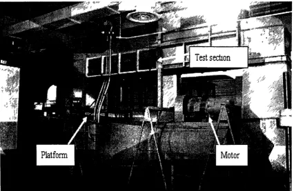
3.1 Wind Tunnel
The work presented here was carried out in a closed loop wind tunnel at the University of
Windsor. The test section is 75 cm high and 75 cm wide at the inlet with a working
length of over 4 m. To accommodate for boundary layer built up, the test section expands
to 77 cm high and 76.5 cm wide at the end. The maximum attainable velocity in the
empty test section was approximately 15 m/s. A preliminary test carried out at a mean
velocity of 10 m/s showed a background turbulence intensity of less than 0.55% at the inlet of the test section in the absence of turbulence producing perforated plates. The
wind tunnel used for conducting this experimental study is shown in Figure 3.1. The
blockage ratio is of 3.2%, which is less than the 5% blockage ratio suggested by previous
investigators [Gross and Sekscienski, 1966; Hucho, 1998].
Figure 3.1 Closed-loop wind tunnel
3.2 Air Deflectors and Truck Model
Air Deflectors
The conventional deflector with a convex surface (Figure 3.2 (a)) is widely used by truck
companies in recent years. To bring new ideas to deflector design, some different shape
deflectors are proposed in this project to investigate their aerodynamic characteristic. The
deflectors have flat surface but with different inclination angles were studied first. Figure
3.2 (b) shows a deflector with 30 degree inclined flat surface. Figure 3.2 (c) shows a
deflector with 45 degree inclined flat surface. For further investigation, a new idea which
is contrary to the convex deflector is proposed. Figure 3.2 (d) shows a deflector with three concave surfaces. Base on the previous study in this area [Hucho, 1998], a deflector
with two concave surfaces on both of the side planes can reduce the drag coefficient up to
30%, which means a significant fuel saving. Considering the airflow around the surfaces
of the truck model (Figure 2.6), the concave surface is supposed to change the aerodynamic characteristic of airflow distinctively and thus reduce the drag force on
truck, especially in a yawing wind condition. To evaluate the effectiveness of the drag reduction by using concave surface deflector, and provide more experimental detail in
this field, the new shape deflector of three concave surfaces is proposed. All deflectors
have the same height which is designed to eliminate the flow separation in the gap region. Tuft flow visualization will be carried out for all those cases to evaluate the effect of the
deflector shape on the airflow characteristics around the truck. The dimensions of different deflectors are shown in Figure 3.3.
(c) Deflector with 45 degree inclined flat surface
(d) Deflector with three concave surfaces
Figure 3.2 Four different shape deflectors
(a) 30 degree flat surface deflector (b) 45 degree flat surface deflector
Side view
A
9rom
<;
^
• s — 7 m m — s
e—lOnm
4
3rw
—>
t
Plan view
(c) Proposed concave surface deflector
Figure 3 3 Dimensions of different deflectors
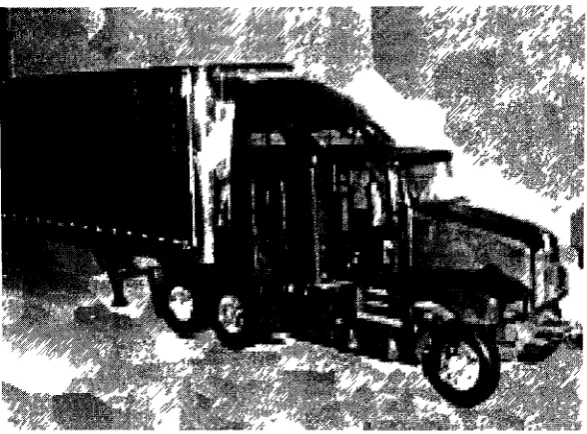
Truck Model
a) Original Kenworth T-600 Truck Model
Three cases of drag force measurement were performed in the wind tunnel tests, using an
existing 1:24 scale truck model of a Kenworth T-600 Tractor with a Great Dane box
trailer. The size of the model varies in length depending on the scale size, which is a
simple reduction in size and is basically fractions of the actual size of a tractor-trailer. A
tractor-trailer that is a 1:24 scale means that it is l/24th the size of the actual truck in
length, which is 60 feet (18.288m) long in "real life", and 2.5 feet (0.762m) long of the
scaled truck model.
The overall dimension of the truck model is 0.173m (Height) x 0.108m (Width) x 0.762m
(Length), as shown in Figure 3.4.
0 762m 0 108m
Figure 3.4 Side and front views of the 1:24 scale Kenworth truck model
After the experiments of tuft flow visualization, three cases were carried out by attaching different deflectors on the same truck model. In the first case, the original deflector with
conventional convex surface was mounted on the top of the tractor, as shown in Figure 3.5. Figure 3.6 illustrates the proposed air deflector, of which all three faces have a concave surface. The third case of drag data was collected using the same truck model but without a deflector, as shown in Figure 3.7 The tractor-trailer gap for this study was
V*l
%-i i*™~ •
mmm^ •»•• ? \ g l '
^y
, ^Figure 3.5 Conventional deflector with convex surface
Figure 3 6 Proposed concave surface deflector
Figure 3.7 Truck model without deflector
3.3 Hot-wire and Load cell System
Hot-Wire System
The velocity measurements were carried out using a single normal hot-wire probe of DISA type 55P11. The hot-wire anemometer used in this experiment is a Dantec
Streamline 55C90 CTA module installed within a Dantec 90N10 frame. The sensor on the probe is 1.25mm long, platinum-coated tungsten wire with a diameter of 5um. The signal was sent to the computer via a National Instrument ATMIO-16E-10 multifunction data acquisition board with a 12-bit resolution at a sampling rate of 40 kHz and low
Figure 3.8 Hot-wire system [CTA: Dantec Streamline® 55C90, I/O- shielded I/O connector]
Load Cell System
The truck model was attached to a load cell secured onto the wind tunnel floor to quantify the drag force. The load cell used in this experiment is an ELG-V-1N-L03M ENTRAN model, which can measure tension or compression force. It has a full scale reading of 1
N, and an over-range limit of 10 N. It was connected to a model MROJHHSG Electro-Numeric Amplifier, which provided a 10 V excitation to the load cell.
3.4 Experimental Setup
Drag Force Measurement
To minimize the impact on the flow, the load cell was attached to the wind tunnel floor, located in front of the elevated plate, which was used to reduce the boundary layer effect (Appendix E). It was connected to the truck model by using a cord, with a certain angle to the wind tunnel floor, which was measured to calculate drag force. A pitot-static tube was secured at the inlet of the wind tunnel, to measure the free stream velocity during the test. A piece of wax paper was place between the tires of the truck model and elevated plate to reduce the friction The blockage ratio in this experimental setup is 3.3%, which
is less than the upper limit of 5% blockage ratio, beyond which corrections of blockage
effect should be applied (Appendix F). The set up is shown schematically in Figure 3.9.
wind tunnel "test section
+ u
pitot tube —NlOQ.dceU elevated plate wind tunnel floor
Figure 3.9 Experimental setup for drag force measurement
During the experiment of drag force measurement, the truck model was not rotating or sliding. Because the free stream velocity was relatively low in this experiment. The
friction between the tires of truck model and the elevated was calculated from the following equation,
Ff=uFn
Where \i is the coefficient of static friction, which is different from the coefficient of kinetic friction when the tires are rotating. Fn is the normal force exerted between the
surfaces, which is the self-weight of the truck model in this study.
Wake Measurements
density and viscosity deviation from the calibrated conditions) on the traverse system
downstream of the model, the movement of which was controlled by a smart motor
program.
wind tunnel t e s t section
Traverse systen
U
Hot-wire Probe
<v> , flft
/ I ~rer
loadcell
Elevated plate Wind -tunnel f l o o r
Figure 3.10 Experimental arrangements for studying wake of the truck model
First, the near wake velocity distribution were measured in the centre plane to investigate
the characteristics of the wake bubble, then experiments were repeated by using the
original deflector and the proposed deflector in side planes, to reveal 3D feature of the
wake bubble. The location of the side planes were chosen at Z = ± 1 inch (0.0254m), Z=
± 2 inch (0.0508m), where Z is the distance from the side plane to the central plane.
The grid systems used for hot-wire measurement are illustrated in Figure 3.11. The starting position of the probes was 1 inch (0.0254m) downstream from the model base, in order to avoid potential probe breakage. The area covered was 5.5 inch (0.14m) in width and 5.5 inch (0.14m) in height. The height of the area covered by the testing grid was the same as that of the trailer.
Two sets of grid systems were used to collect points. Firstly, 121 points were measured in
the first grid system (11x11); the interval between each two points was 0.5 inch
(0.0128m). Then, moved the starting point 0.25 inch (0.0064m) further downstream,
another 121 points were measured in the second grid system (11x11); the interval
between each two points was 0.5 inch (0.0128m). Thus, 242 points were measured totally
for each section to make sure enough points would be collected to get the precise velocity
distribution in wake area. The interval between each two horizontal points was 0.25 inch
(0.0064m); between each two vertical points was 0.5 inch (0.0128m).
model truck
7 i nch
I — 5 . 5 i n c h —
. . testing grUi 1 inch
5.5 inch
L*
Chapter 4 RESULTS AND DISCUSSIONS
4.1 Tuft Flow Visualization
The airflow around the tractor-trailer is related to the magnitude of the drag force in that
area [McLandress et al, 2001], a series of tuft flow visualization tests [Villanueva, 2002] were carried out to investigate the flow pattern around truck model when using different deflectors.
(a) Flow pattern on the top surface of trailer box when using conventional deflector
(b) Flow pattern on the top surface of trailer box when using the proposed three concave surfaces deflector
(c) Flow pattern on the top surface of trailer box when using inclined flat surface deflector (30 degree)
(d) Flow pattern on the top surface of trailer box when using inclined flat surface deflector (45 degree)
Figure 4.1 Flow pattern around truck model when using different deflectors
The air flow around the top surface of the trailer box in Figure 4.1 (a) and Figure 4.1 (b)
seems smooth and without any separation or vortex. In Figure 4.1 (c) and Figure 4.1 (d), by using the inclined flat surface deflectors, it can be seen that a vortices forms in the front area of the trailer top surface. The flow characteristics on the side surface of the truck model using all the four different deflectors were also studied. A slight difference
was observed among all the cases. It indicated that the change of deflector didn't significant affect the flow around the side surfaces of the truck. Another reason could be, by using such a small-scale truck model, the difference is not obvious to be observed.
4.2 Impact of Friction
The friction between the tires of truck model and the elevated plate could significantly distort the load cell reading for drag. To evaluate such an impact, a piece of wax paper was placed under the model truck tires to minimize friction. An oil sheet was applied to fill the space in the pattern of the tires, to make sure the truck model is able to move freely when the force is applied.
To justify the effectiveness of using wax paper and oil in minimizing the impact of friction between vehicle tires and elevated plate on drag measurement, a series of experiments were conducted on drag measurement by using a simple bluff body with and without wax paper and oil, the results were compared with existing literatures.
The experiments were conducted on a circular cylinder with a length of 75cm and
diameter of 4.85cm. The cylinder is hollow and with a thickness of 0.5cm, thus, the
contact area between the bottom of the cylinder and the wind tunnel floor is reduced
close to the contact area between the tires of the truck model and the elevated plate. Thus
the experimental results can be applied to the truck model cases. It was mounted on the
floor of wind tunnel test section connected to the loadcell system by four strings with
angles of a and a', as sketched in Figure 4.2 and Figure 4.3.
Figure 4.2 Schematic of the experiment setup for drag force measurement on cylinder
Drag fore measurement and calculation procedure
The loadcell was attached to one of the top upstream strings and one of the bottom upstream strings respectively, to measure the net load on those two strings. Due to the symmetric layout of the strings, the drag of the cylinder was therefore determined by the adding of the horizontal streamwise components of the net loads in those two strings multiplied by two, which was calculated below,
As shown in Figure 4.3
a, a , p, P' = geometrical angle of cylinder setup
FD-TOP=F I * sina cosP (along the wind direction )
FD-BOTTOM=F3* sina cosp' (along the wind direction) Because Fi and F2, F3 and F4 are symmetrical in geometry
The total drag force on the cylinder is
F Total=2FD-TOP+2FD-BOTTOM
The equation used to calculate the drag force is
F(N)=0.615Floadce„(mV)
Which is deduced from the calibration [Strain Sense Ltd., 2007]
FD = CD (pV2 A/2)
In this case,
CD=2FTotai/pV2A
Re=VD/v
where V=6m/s, 8m/s, lOm/s, 12m/s
A=D X Lcyiinder=4.85cm X 75cm=363.75cm2=0.0364m2
D=0.0485m
Figure 4.4 Drag coefficients as a function of Reynolds number on friction testing.
Figure 4.4 shows that without placing wax paper and oil between the wind tunnel floor and the cylinder, the drag coefficient is between 1.28 and 1.30. By utilizing the wax paper and oil to reduce the friction, the drag coefficient is deduced to 1.19 to 1.20 at the same range of Reynolds numbers. Most of those points are within a reasonable range compared with the previous studies, which is summarized in Figure 4.5.
10E2
10E1
10E0
10E-1
10E0
r>
10ES 10E4 10E6
Re
Figure 4.5 Experiment results compared to the standard curve
The standard curve in Figure 4.5 is derived from:
[Yeboah and Rahai, 1997; Lim and Lee, 2004; Schewe, 1983; Sumner, 2004, Golling,
2006; Poulin and Larsen, 2007].
By plotting the present experimental results in Figure 4.4 into the standard curve in
Figure 4.5, it is observed that, only one point at Reynolds number 2.5x10⁴ is slightly
higher than 1.2 (maximum CD Value from previous study at the same Reynolds number). It can be concluded that the method of using the wax paper and oil to reduce friction suitable. It can be utilized to the truck model case for further investigation.
The test was then repeated for the truck model case The drag of the model truck measured with and without wax paper is presented in Figure 4.6 at 5 different Reynolds
0.8 0.7
0.6
0.5
CD0 . 4
0.3
0.2
0. 1 0
-3 4
» A
— — • •
W with wax paper and oil • without wax paper and oil
5 6 7
Re(10
5)
Figure 4.6 Impact of friction on drag measurement (conventional deflector)
From Figure 4.6, it reveals that the friction between the truck model tires and the elevated plate affects the drag measurement results considerably. It can be seen that, drag
coefficient is much higher (46% maximum at Re=3xl05) in the absence of the wax paper.
As the Reynolds number increases, the difference in drag coefficient between these two cases becomes smaller, at the maximum studied velocity of 14m/s (Re=7xl05), the drag
coefficient of the case without wax paper is about 30% greater than that of the case with
wax paper, which indicates the effect of friction between the model truck tires and the elevated plate reduces at higher Reynolds number. After minimizing the impact of friction, the drag coefficient obtained from this study is in the range of 0.38 ~ 0.54, which agrees with the existing data from previous work of Berta and Tacca [1980], and Cooper [2003]: The drag coefficient of the truck with a streamlined cab at a zero yaw angle and a
Reynolds number of at half a million is in the range of 0.30-0.55.
4.3 Drag Force Measurements
A series of tests were carried out under smooth flow condition (Tu<0.55%), at nominal
mean flow velocities of 6m/s, 8m/s, lOm/s, 12m/s and 14m/s, which correspond to
Re=3xl05, 4xl05, 5xl05, 6xl05, 7xl05, respectively. The drag coefficient of the model
truck measured using the proposed concave deflector, conventional deflector and without
deflector is presented in Figure 4.7.
0.8
0.7 r
0.6
0.5
CD 0.4
0.3
0.2
0.1
0
"without deflector -original deflector -proposed deflector
Re(10
5)
Figure 4.7 Drag coefficients of model truck with different air deflectors under smooth flow condition
From Figure 4.7, by comparing the two CD-Re curves of the proposed deflector and the
conventional deflector, it can be seen that under smooth flow condition, when the Reynolds number is relatively low (Re=3xl05), the drag coefficient of the proposed
deflector, results show that the drag coefficient is relatively higher than that with the
conventional convex deflector (29% maximum).
4.4 Impact of Y a w Angle
A zero yaw angle corrsponds to driving in still wind, which never occurs in reality and
can not provide sufficient indication of aerodynamic characteristics in real operation.
Thus, the effect of yaw angle on drag coefficient should be taken into consideration in
wind tunnel study. In this series of test, drag measurement for the tractor-trailer model
with different air deflectors in yawed wind was conducted. Due to the limited width of
the wind tunnel, a yaw angle range of -5° to +5° was investigated.
1.2
1
0.8
c5 0.6
0.4
0.2
0
Yaw Angle Effect
• ^ ^ \ ^ ^ ^ ^ ^*
-i
5° 0° —
Yaw angle
—•—Original deflector —A—Proposed deflector —•—Without deflector
5°
Figure 4.8 Influence of Deflector Shape versus Yaw Angle (Re=6 X 10⁵)
From Figure 4.8, a considerable increase in CD with increasing yaw angle is observed in
all three cases tested. The CD difference between the proposed deflector case and the original deflector case becomes larger at ± 5° yaw angle, which indicates that in a yaw
wind condition, the proposed concave deflector can reduce the drag force applied on the
truck model more significantly. More experiments need to be carried out in larger yaw angle conditions to confirm this finding.
4.5 Wake Bubble
It is known from Yang's study [2008] that details of vehicle shape affect the aerodynamic
characteristics of the wake area. As a further research, the characteristics of the wake
bubble are investigated by changing different air deflectors. The first series of
experiments were carried out in the centre plane behind the truck model.
Considering the importance of the recirculation length in the study of wake characteristic,
First of all, how to deduce the recirculation length is illustrated in Figure 4.9.
o &
H ° •
3»
~ O St O . 1
.s&
^ ^ V s ^
>C -1
O O •!& 1 1
^ M
~~1
^L o o o a o S3 . 3 5> . "1 — — — — o <o 3 2c S 7 3
: i ?^ f c ' j c > * 3
X .
o O - © 1 1 t » 2> S
Figure 4.9 Near-wake time-averaged velocity distribution and recirculation length in
each horizontal line at the vertical central plane [Duell and George, 1993]
As shown in Figure 4.9, Um is local mean velocity, U<x> is the free stream velocity. The
recirculation length is the largest Xr. deduced from the distance between the model rear
the distance from the model rear end to the point where the slope of velocity profile in the
streamwise direction is 0 and curvature is upward (positive).
In Figures 4.10 (a)-(c), three collections of stagnation points along the horizontal lines in
the measuring grid are shown, the recirculation length and the bubble shape (consisted of
Xr in each horizontal lines) obtained by using different air deflectors are illustrated.
_ _ j «
0
o
o
o
o
1
e.93
•0.85
-0.71
-0.63 p
0.4§ j |
i*0.41 ,j
' I
,0.34 f i—-—'—%P—' 1 '—' • ' '—~—» "i *-0.26 0.151 0.22 f 0.29 0.37 0.44 0.51 0.59 0.66 0.74 0.81 0.89
.... XiH
Figure 4.10 (a) Bubble shape of the truck model using original deflector in the wake at Re=5xl05
f
"i- ,.//<> y a a a g ^ r ...(Jitay^.^gy
o
o
0
0
0
0.85
% 0.7*
0.71
10.63 f
0.56
0.49
0.41
0.34
%n P f -
IX
40.26!0.15^0.22 0.29 f U 3 ? 0.44 0.51 . 0.59 4 0.66 0.74 0.81»0.15
Figure 4.10 (b) Bubble shape of the truck model using proposed deflector in the wake at Re=5*103
n
<Q&£sL.m^fXSitfqBSmm.^it-o
o
o
o
o
o
0
-0.7*
T 0 . 7 1
*-0.w
-049
•0 41
-034
• '"I' I I1 •"• ' ' I ' ' ' • f ^ L
0.1$ 0.22 t.2» 0.37 0.44 0.51 0.50 0.00 0.74 0.11 0.M X/H
00.28
In term of recirculation length, compare Figure 4.10 (a) and Figure 4.10 (b), the
conventional deflector and the proposed one yield 0.71 versus 0.73, which means the
later case has a relatively larger (longer) near wake region than the former one. The
reason may caused by the delayed flow separation around the frontal area of the truck
model by using the proposed concave deflector.
Concerning the shape of the bubbles, connecting the lower 6 points in Figure 4.10 (b), a "two-dimensional bubble" appears which is more rounded and circular comparing to the
one form in Figure 4.10 (a). In Figure 4.10 (c), although mathematically the stagnation
points in some horizontal grid lines can still be determined, but by connecting these points, it really doesn't look like a "real bubble", it is much blunt. Those two points
appear in the upper region in Figure 4.10 (c) may be caused by unexpected vortex and need to be further investigated.
To deduce and understand the relationship between the bubble shapes and drag force, some relevant previous research work was studied. According to Roy and Srinivasan's work [2000], CFD was used to obtain the external flow around the truck models of
different frontal shape; an on-road speed of 60 mph was simulated in that study. The results show that, the details of flow vector behind a truck model with rectangular front (as in our case: truck model without deflector) showed strong recirculation and resultant source of pressure drop, which indicates a larger drag force. Less flow vortices are shown
behind a truck model with the rounded frontal shape (as the conventional deflector in our case). It indicates a smaller drag force, which leads to over 28% drag reduction.
Comparing the results in Figures 4.10 (a)-(c) to Roy and Srinivasan's work, there is less vortex forms to disturb the bubble shape in the wake area by using the proposed deflector in Figure 4.10 (b), thus, leads to a less drag force. On the other hand, in the case of truck model without deflector, more vortices behind the truck model form to disturb the bubble shape (Figure 4.10 (c)), which leads to a larger drag force. To sum up. the proposed deflector leads to less drag force comparing to the conventional one, and the truck model
![Figure 2.1 Graphic depicting the impact of aerodynamic uncertainty on horsepower requirements for a heavy vehicle tractor-trailer truck [Wood and Bauer, 2003]](https://thumb-us.123doks.com/thumbv2/123dok_us/1501779.1183838/19.611.157.443.391.648/figure-graphic-depicting-aerodynamic-uncertainty-horsepower-requirements-vehicle.webp)

![Figure 2.7 Tractor-trailer configuration: add-on devices and body-details study [Berta and Bonis, 1980]](https://thumb-us.123doks.com/thumbv2/123dok_us/1501779.1183838/26.611.153.439.243.525/figure-tractor-trailer-configuration-devices-details-berta-bonis.webp)
![Figure 2.12 Pressure distribution on a road vehicle at different Re: no screen [Wiedemann, 1989]](https://thumb-us.123doks.com/thumbv2/123dok_us/1501779.1183838/31.611.106.510.71.289/figure-pressure-distribution-road-vehicle-different-screen-wiedemann.webp)


![Figure 3.8 Hot-wire system [CTA: Dantec Streamline® 55C90, I/O- shielded I/O connector]](https://thumb-us.123doks.com/thumbv2/123dok_us/1501779.1183838/44.619.123.502.58.281/figure-hot-wire-cta-dantec-streamline-shielded-connector.webp)

