a Corresponding author: [email protected]
Update on the status of the ITER ECE diagnostic design
G. Taylor1a, M. E. Austin2, A. Basile1, J. H. Beno3, S. Danani4, R. Feder1, S. Houshmandyar2, A. E. Hubbard5, D. W. Johnson1, A. Khodak1, R. Kumar4, S. Kumar4, A. Ouroua3, S. B. Padasalagi4, H. K. B. Pandya4, P. E. Phillips2, W. L. Rowan2, J. Stillerman5, S. Thomas4, V. S. Udintsev6, G. Vayakis 6, M. Walsh6, and D. Weeks3
1Princeton Plasma Physics Laboratory, Princeton, NJ 08543, USA
2Institute for Fusion Studies, University of Texas at Austin, TX 78712, USA 3Center for Electromechanics, University of Texas at Austin, TX 78758, USA 4
ITER-India/Institute for Plasma Research, Bhat 382428, Gandhinagar, India 5Plasma Science and Fusion Center, MIT, Cambridge, MA 02139, USA
6ITER Organization, Route de Vinon sur Verdon, 13115, St Paul Lez Durance, France
Abstract. Considerable progress has been made on the design of the ITER electron cyclotron emission (ECE) diagnostic over the past two years. Radial and oblique views are still included in the design in order to measure distortions in the electron momentum distribution, but the oblique view has been redirected to reduce stray millimeter radiation from the electron cyclotron heating system. A major challenge has been designing the 1000 K calibration sources and remotely activated mirrors located in the ECE diagnostic shield module (DSM) in the equatorial port plug #09. These critical systems are being modeled and prototypes are being developed. Providing adequate neutron shielding in the DSM while allowing sufficient space for optical components is also a significant challenge. Four 45-meter long low-loss transmission lines transport the 70-1000 GHz ECE from the DSM to the ECE instrumentation room. Prototype transmission lines are being tested, as are the polarization splitter modules that separate O-mode and X-mode polarized ECE. A highly integrated prototype 200-300 GHz radiometer is being tested on the DIII-D tokamak in the USA. Design activities also include integration of ECE signals into the ITER plasma control system and determining the hardware and software architecture needed to control and calibrate the ECE instruments.
1 Introduction
Considerable progress has been made on the design of the ITER electron cyclotron emission (ECE) diagnostic since the status of the design was presented at the EC-18 workshop in Nara, Japan in April 2014 [1]. The ECE diagnostic will provide important information on the time evolution of the electron temperature profile (Te(R)), magneto-hydrodynamic (MHD) fluctuation spectra, non-thermal electron behavior and the ECE radiated power loss. The design is being carried out through a close collaboration between teams in the USA domestic agency (US-DA), India Domestic Agency (IN-DA) and at the ITER Organization (IO) in France. The design is currently midway through the detailed preliminary design phase that will culminate in a preliminary design review in 2017. A radial and oblique view [2] are still included in the design, but since 2014 the oblique view has been redirected to reduce collection of stray millimeter radiation from the electron cyclotron heating (ECH) system. A major challenge has been designing the front-end ECE diagnostic shield module (DSM) in equatorial port plug #09, and the components located therein. These
integration of the ECE signals into the plasma control system (PCS) is being addressed. This work includes determining the hardware and software architecture needed to control and calibrate the ECE instruments, and to store and analyze the ECE data. This paper updates the status of these design and prototyping activities. Section 2 covers the design of front end components, section 3 covers the design of components between the DSM and the ECE instrumentation room, and section 4 describes instrumentation in the ECE room, and provides an overview of the software needs and information flow between ECE instrumentation and the ITER plant, including the PCS.
2 Front-end components
The DSM design has significantly changed over the past two years in order to address issues related to neutron shielding and structural integrity. There have also been
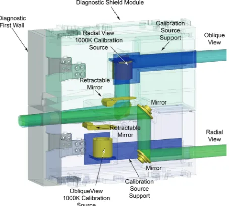
changes in the optical design and in how the mirrors that switch between the plasma views and the calibration sources are controlled. Figure 1 shows a side view of the ECE DSM. The DSM is now comprised of upper and lower shielding modules that include internal spaces for optical components. Previously the DSM had three shielding sections split vertically but this complicated connections for water cooling. It would be even better to have just one shielding module but this cannot be manufactured using conventional machining. It is concievable in the future that such a single shielding module could be created with a 3D printing additive manufacturing technique. The diagnostic first wall (DFW) module is bolted to the two shielding modules at the front of the DSM. The concept for supporting the calibration sources is presently to bolt them to plates intalled on the outside of the DSM (Fig. 2). These plates
extend to the back of the DSM and include a channel machined inside to carry cables.
The width of the DSM was reduced in 2014 requiring the oblique viewing angle to be reduced from 13o to 11.5o from radial (Fig. 3). Also the oblique view direction was redirected to the opposite toroidal direction to reduce the possibility of stray millimeter wave radiation entering from the ECH system.
During the past two years there has been significant design and prototyping activity in the USA on the hot calibration sources that will be located in the DSM. A prototype design (Fig. 4) is being developed that minimizes the use of brittle materials to mitigate high shock loads, avoids direct water cooling to reduce failure points, and uses indirect cooling from the DSM wall. The design uses a Nichrome heating element embedded in an Inconel heating block for improved mechanical support and protection. Two heating configurations are being explored; indirect heating of the Silicon Carbide (SiC) emitter through radiation to avoid direct mechanical contact between the metallic surface and the ceramic emitter back surface, and direct contact heating where the heater is in contact with the emitter. While indirect heating is the preferred option, since it has mechanical benefits, it was found in early in-vacuum testing of a commercial MeiVac [3] embedded Inconel heater that surface emissivity not only varies significantly with temperature, but also due to the formation and Figure 1. Side view of front-end optics in the ECE DSM
showing calibration sources and retractable mirrors that switch in the calibration sources to the radial and oblique views and
calibration source support brackets (blue).
Figure 3. Top view of ECE DSM showing calibration source locations.
Figure 2. Calibration source support plate concept. (a) Rear view of ECE DSM, (b) hot source mounting plate, and (c)
sublimation of oxide layers during heating. A vibration
analysis of the ECE hot sources is being conducted. There are various fast transient electromagnetic loads that can result in vibrations of the calibrations sources. These electromagnetic loads can be driven by major disruptions and plasma vertical displacement events that induce inertial loads on the Port Plug and DSM. Results of the vibration analysis so far indicate these loads can induce 50-60 Hz vibrations with a maximum acceleration of 8 g.
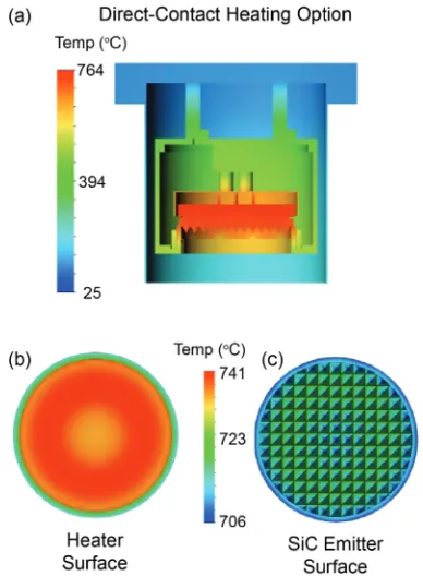
Detailed thermal analysis (Fig. 5) and experimental evaluation of prototype hot sources with direct and indirect heating of the SiC emitter is currently being conducted. So far good agreement has been found between the thermal analysis and experiment.
The design presented at EC-18 had wire rope actuators controlling the remotely activated mirrors that switch between viewing the calibration sources and the plasma. The wire rope concept required four penetrations through the port plug back plate that increased neutron streaming and also required sophisticated remote handling. One concept being considered now is to use piezoelectric actuators mounted on the mirrors. These actuators can be made magnetic field and ultra-high vacuum compatible, and require no mechanical feedthroughs. The piezoelectric actuators can be installed on the remotely actuated mirrors in such a way as to allow the mirrors to act as shutters blocking the calibration sources when they are retracted for plasma ECE measurements, this was not possible with the wire rope design. Furthermore commercial piezoelectric actuators are available that have two piezoelectric drives on the same axle. This arrangement provides redundancy if one of the piezoelectric drives were to fail. Available commercial piezoelectric actuators have a pointing accuracy of < 0.1o
and can operate at up to 200 o
C. Prototype testing of a piezoelectric actuator will be conducted during 2016. If the prototype testing shows the concept is viable, the piezoelectric actuator will be subjected to a neutron fluence corresponding to the lifetime exposure it would be subjected to in the ECE DSM. Another concept being considered is a single rod actuator for each remotely activated mirror. The mirror would be held in the plasma viewing position by a spring or counter weight and the rod would push on the mirror to switch the mirror to view the calibration source.
3 Components between the front-end
and the instrumentation room
The vacuum window assemblies at the back of the DSM will be provided by ITER but the design of the interface
Figure 6. Concept for the interface between the vacuum window assembly and the polarization splitters.
Figure 5. Thermal analysis of a hot source using the direct-contact heating and 1.2 kW of heating power. (a) a vertical
section through the calibration source. (b) The heater surface and (c) the SiC emitter surface. The color scales indicate the predicted temperatures of source components.
between the vacuum windows and the polarization splitters is the responsibility of the US-DA. The remainder of the transmission line system connecting the front-end to the ECE room in the Diagnostics Hall, including the polarization splitters, is the responsibility of the IN-DA.
Figure 6 shows the present concept for the interface between the vacuum window assembly and the polarization splitters. A fire retardant cloth sleeve that is slightly over pressured with either dry air or nitrogen provides a compliant coupling between the vacuum window assembly and the polarization splitters. Controlled leakage of over pressured gas can ensure evacuation of water vapor from the transmission line. A field stop, probably made from SiC, will be located between the double vacuum window assembly [4] and the compliant coupling to filter unwanted high order modes.
A prototype polarization splitter box is being assembled
by the IN-DA.
Each polarization splitter box containstwo Gaussian telescopes constructed from three
ellipsoidal mirrors (Fig. 7). The calculated cross polarization loss is 31.1 dB at the 800 mm focal length mirror and 30.4 dB at the two 524 mm focal length mirrors. The calculated higher order mode loss is 34.1 dB at the 800 mm focal length mirror and 33.4 dB at the two 524 mm focal length mirrors. 10-15 m lengths of prototype smooth walled circular waveguide transmission line sections with an internal diameter (ID) of 72 mm have also been fabricated for testing the attenuation. The transmission lines will be evacuated to mitigate absorption by water vapor.
4 ECE instrumentation room
Two, high throughput, reciprocating Martin-Puplett Fourier Transform Spectrometers with a spectral range of 70-1000 GHz, a frequency resolution ≤ 5 GHz and a scanning repetition rate ≤ 20 ms will be provided by the
IN-DA. The IN-DA has ordered a prototype Michelson interferometer from Blue Sky Spectroscopy [5]. The instrument will operate in vacuum to avoid water vapour absorption. The design of the optical layout and optical components has been completed and a dual channel detector system has been tested. The testing of the scanning engine and laser metrology system is underway. During 2017 the prototype Michelson interferometer will be used with a 500o
C blackbody calibration source to test prototypes of the transmission line waveguide components, including the prototype polarization splitter. The IN-DA will also provide the “Low Frequency” 122-230 GHz heterodyne radiometer system. A hybrid splitter, consisting of quasi-optical diplexer followed by two waveguide diplexers, will distribute the 122-230 GHz radiation into four bands. The quasi-optical splitter unit will use a Gaussian beam telescope and a frequency selective Dichroic beam splitter. The four receivers will have a total of 58 channels: a 16 channel 122-138 GHz receiver with 0.5 GHz bandwidth per channel, a 14 channel 141-168 GHz receiver, a 15 channel 172-200 GHz receiver and 13 channel 205-230 GHz receiver. All three higher frequency receivers will have 1 GHz bandwidth per channel. The IN-DA is developing a high temperature calibration source (6) that will be used in the ECE instrumentation room to allow more frequent calibration of the ECE instruments than will be possible using the calibration sources in the DSM.
The US-DA is responsible for providing the “High Frequency” radiometer system. Originally this system was to cover 244-355 GHz, but to better match the ITER plasma operating scenarios the frequency coverage was changed to 220-340 GHz and the number of standard resolution (1 GHz bandwidth) channels was increased from 48 to 60. There will also be 16 high-resolution (200-250 MHz bandwidth) channels that use YIG filters to tune within a 2-18 GHz frequency range. The mixer bank will have three 2-40 GHz filters. There will be two,
temperature-controlled, 30 dB intermediate frequency (IF) amplifiers per bank, with adjustable attenuators covering 0-30 dB in 1 dB steps. Pad attenuators in front of each detector will be used to fine tune sensitivity. The Figure 7. Schematic diagram of the polarization splitter.
video amplifiers will have a voltage gain of 100-400 and a bandwidth of 500 kHz. An important overall goal of the design for the IF filter bank is to achieve stable response and good sensitivity for each channel and easy access for
adjustments and changes. A prototype 200-300 GHz
radiometer (Fig. 8), that employs highly-integrated millimeter wave technology, developed by Virginia Diodes [7], is being tested on the DIII-D tokamak at General Atomics in the USA [8, 9]. Third and fourth harmonic plasma ECE measurements from the prototype radiometer are being compared to data from a Michelson interferometer.
Because there are only two Michelson interferometers in the baseline ECE instrumentation there will need to be switches in the ECE room that switch the inputs of the two Michelson interferometers between the radial O-mode, the radial X-mode, the oblique O-mode and the oblique X-mode transmission lines in order to check that the ECE spectrum is thermal and to measure the total ECE power. An ad hoc working group with members from the IN-DA, US-DA and IO was setup to identify the simplest way to achieve this flexibility and agree on the layout of instrumentation in the ECE room.
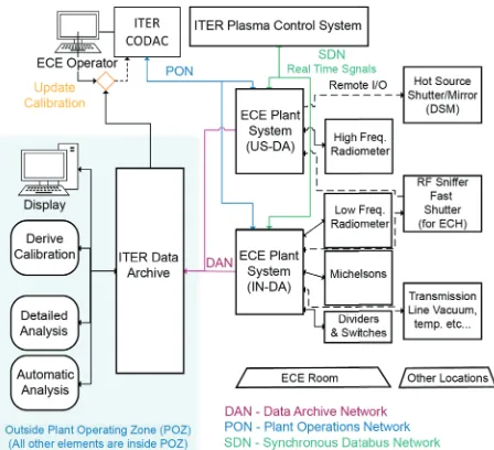
Another important aspect of the preliminary design phase is to decide the software needed to control and calibrate the ECE instrumentation, and to record and analyze the ECE data. Unlike current fusion experiments, ITER employs a concept referred to as the “Plant Operating Zone” (POZ). Because ITER is a nuclear facility the POZ requires strict safeguards. Figure 9 shows a simplified schematic of the ECE systems and data networks within and outside the POZ. There are two ECE Plant Systems that send and receive data inside the POZ via a relatively slow Plant Operations Network (PON). Signals to the PCS for NTM and Te(R) control will be sent over a faster
Synchronous Databus Network (SDN). Another ad hoc working group with members from the IN-DA, US-DA and IO has been setup to determine what real time signals
need to be provided for NTM and Te(R) profile control.
For Te(R) control 32 channels of Te(R) data, with
channels separated by a/30 (where a is the plasma minor radius) at a digital sampling rate of 100 Hz and with a latency of 2.5 ms should be sufficient, but for NTM control the data requirements are more challenging. An n = 2 NTM may have frequencies up to 10 kHz, requiring digital data sampling rates up to 30 kHz. However the rate of change of NTM parameters would be much slower
(~ 1 ms). Radial coverage of the Te(R) data for NTM
control will need to be closely spaced with a channel spacing of a/80 over the region between q=1 and q=2.
Options for providing Te data to the PCS are under
consideration by the ECE and ITER PCS teams. The ECE diagnostic system could supply a set of Te(t) signals at a rate greater than the NTM frequency and/or use high level data processing in the vicinity of the ECE diagnostics to supply NTM parameters at a lower rate of ~1 kHz. These and other details will be determined as the control approaches are decided and the ECE instrumentation and control system designs progress.
5 Summary
Through close collaboration, design teams in India, the US and at the ITER site in France have made significant progress during the past two years designing the ITER ECE diagnostic system, despite the significant technical challenges presented by the ITER environment. In order to guide the design process prototypes of key system components, including a 200-300 GHz radiometer, a 70-1000 GHz Michelson interferometer, a 70-1000 K hot source, piezoelectric actuator for the shutter/mirrors in the DSM, and broadband quasi-optical transmission line components are being fabricated and tested. Prototype testing will help guide the preliminary design process that will culminate in a Preliminary Design Review in 2017.
Acknowledgements
This work is supported by US DOE Contract No. DE-AC02-09CH11466. All US activities are managed by the US ITER Project Office, hosted by Oak Ridge National Laboratory with partner laboratories located at the Princeton Plasma Physics Laboratory and the Savannah River National Laboratory. The project is being accomplished through a collaboration of DOE Laboratories, universities and industry. The views and opinions expressed herein do not necessarily reflect those of the ITER Organization.
References
1. G. Taylor, et al., EPJ Web of Conferences 87, 03002 (2015); DOI: 10.1051/epjconf/20158703002.
2. G. Taylor and R. W. Harvey, Fus. Sci, Tech. 55, 64 (2009).
3. MeiVac Inc heater :
http://www.meivac.com/htr-substrate-heater-family/
Figure 9. Schematic diagram of information flow for major ITER ECE system elements. Data to and from the ECE Plant
Systems will be via the Plant Operations Nework (PON, blue), the Synchronous Databus Network (SDN, green), and
4. V. S. Udinstev, et al., “Primary window assemblies for microwave diagnostics in ITER”, Paper TECH-P-4, EC-19 Conference (2016).
5. Blue Sky Spectroscopy:
http://blueskyspectroscopy.com/?page_id=13
6. R. Kumar, et al., “Characterization of in-house
developed high temperature black body source in frequency range 70-1000 GHz”, Paper ECE-P-5, EC-19 Conference (2016).
7. E. W. Bryerton, et al, “A compact and reliable
200-300 GHz receiver for the ITER ECE system”, Proc. 39th
Int. Conf. on Infrared, Millimeter, and Terahertz Waves, Tucson, AZ, USA (2014); DOI:
10.1109/IRMMW-THz.2014.6956470
8. M. E. Austin, et al., “Testing of the ITER-ECE
prototype receiver and related components on
DIII-D”, Paper JP12.00070 Bull. Am. Phys. Soc. 60
No. 19. (2015).
9. S. Danani, et al., “Testing of the Prototype Receiver