Image Registration using Discrete Wavelet
Transform and Particle Swarm Optimization
Jitendra Pramanik#1, Sunita Dalai*2, Debaraj Rana#3 #1
M.TechScholar , #3 Asst. Professor, Dept. Of ECE, Centurion University of Technology & Management, Odisha
Bhubaneswar, Odisha, INDIA *
Asst. Professor, Dept. Of ECE
Centurion University of Technology & Management, Odisha
Bhubaneswar, Odisha, INDIA
Abstract- The term image registration basically denotes the process of alignment of images .In recent years, the rapid growth in the field of military automatic target recognition remote cartography ,computer vision, image fusion, medical imaging, and astrophotography has established the need for the development of good image registration technique. Image registration is a process in which final information is gained from different data sources. It is a process of aligning two images acquired by same/different sensors, at different times or from different viewpoint. This paper presents the image registration techniques based on extracting interest point area of scene images using Discrete wavelet Transform and PSO. The root mean square error is used as similarity measure for finding out the area of interest
.
Keywords- Discrete wavelet Transform (DWT), PSO, Interest Point Area Extraction, Image Registration.
I. INTRODUCTION
Image registration is the process of transforming different sets of data into one coordinate system. Data may be multiple photographs, data from different sensors, times, depths, or viewpoints. Image registration process has variety of application as in the field of biological imaging, medical imaging brain mapping. It is also being for compiling and analyzing data and images coming from satellites. Registration process is very essential for comparing and integrating the data obtained from different measurements. It can also be defined as the process of geometrically aligning one image with another image of the same scene taken from different viewpoints or by different sensors. The idea is to transform different sets of data into one coordinate system [2].
The nonalignment of images of same scene can be described by various reasons like calibration issues; setup errors of scanning machine, different scan geometry like slice position, orientation, magnification, thickness of different sensors. The non alignment would have occurred due to relative motion between the camera and object planes. Hence registration of the non-aligned images is done before any other image processing steps.
Image registration involves following basic steps. 1. Detect Features
2. Match corresponding features 3. Infer geometric transformation
4. Align one image to other.
An image feature is any portion of the image that can potentially be identified and located in both the images. It can be Points, lines or corners present in the images. Corresponding feature matching deals with matching features of one image with the corresponding features of the other image having common properties [1].
Image registration algorithms can be broadly classified into two categories according to matching method
Area based methods (ABM) Feature based methods (FBM)
A. Area-Based Methods:
Area based methods are classical image registration methods. It put emphasis on the feature matching step than on their detection. No features are detected in these approaches so the first step of image registration is omitted. Cross correlation matching and least square matching are the most commonly used are based methods [1].
B. Feature-Based Methods
The feature based approach is based on the extraction of salient structures feature in the images. The feature extracted here can be of points (region corners, line intersections, points on curves with high curvature), lines (region boundaries, coastlines, roads, rivers), Significant regions (forests, lakes, fields) etc. These extracted features should be spread all over the image and must be efficiently detectable in both images. They are expected to be stable in time to stay at fixed positions during the whole experiment [2].
ambiguity in smooth (low texture) areas. Feature-based algorithms face the additional problem of the effect of outliers (points with no correspondences) on the results [5].
The accuracy of a any image registration algorithm is generally affected by the segmentation and feature extraction algorithm. Therefore researching and finding a more accurate and faster image registration algorithm is a very important. The basic advantage of a feature based method, where a matching algorithm is sought between corresponding objects within the images, is approximately invariance for the intensity characteristics of the pixels. However this method is very sensitive to the error evolving in feature extraction and matching process [12].
II. DISCRETE WAVELET TRANSFORM (DWT)
The wavelet transform (WT) has gained widespread acceptance in signal processing and image compression. Because of their inherent multi-resolution nature, wavelet-coding schemes are especially suitable for applications where scalability and tolerable degradation are important. The wavelet transform is computed separately for different segments of the time-domain signal at different frequencies. Multi-resolution analysis: analyzes the signal at different frequencies giving different resolutions.
Discrete wavelet transform is any wavelet transform for which the wavelets are discretely sampled. It captures both frequency and location information. It provides spatial and frequency representations of the image and also motivates to use it for feature extraction. It decomposes the input data into several layers of division in space and frequency and allows us to isolate the frequency components introduced by intrinsic deformations due to expression or extrinsic factors (like illumination) into certain sub-bands. There exists a variety of wavelet families depending on the choice of the mother wavelet. In this paper we are using the DWT which is based on the features extracted from a Haar Wavelet Transform.
The Haar wavelet transform is a widely used technique. It has an established name as a simple and powerful technique for the multi-resolution decomposition of time series [15] . The basic idea of discrete wavelet transform is that images processed are transformed to a multi differentiated format in which the image is decomposed into sub image of different spatial domain and independent frequency district [14]. After the original image has been DWT transformed, it is then decomposed into four different frequencies in which one is low-frequency district and the other three are high frequency districts. Those frequency districts are labelled as LL,LH HL HH.
In Figure 1 at each level of the wavelet decomposition, four new images are created from the original image of N x N pixel. The size of these new images is reduced to ¼ of the original size therefore the new size is N/2 x N/2. The new images are named according to the filter that is applied to the original image in horizontal and vertical directions.
For an example the LH image is a result of application of the low-pass filter in horizontal direction and high pass filter in the vertical direction. Hence the four images produced from each decomposition level are labelled as LL, LH, HL, and HH. The LL image is considered to be a reduced version of the original but retains most details. The LH image contains information of horizontal edge features, while the HL contains information of vertical edge features. The HH have only the high frequency information .HH is very noisy .Therefore it is not useful for the registration process. Hence in wavelet decomposition, the LL image is used for producing the next level of decomposition [15].
Fig 1. A 3-level wavelet decomposition of an N x N-pixel image
III. PARTICLE SWARM OPTIMIZATION (PSO)
PSO algorithm is a population-based search algorithm based n the simulation of the social behaviour of birds within a flock. In PSO, each single solution is a “particle”. All of the particles have fitness values which are evaluated by the objective function to be optimized, and have velocities which direct the flying of the particles. The particles fly through the problem space by following the personal and global best particles. The swarm is initialized with a group of random particles and it then searches for optima by updating through iterations. In every iteration, each particle is updated by following two “best” values. The first one is the best solution of each particle achieved so far. This value is known as pbest solution [16, 17].
Another one is that, best solution tracked by any particle among all generations of the swarm. This best value is known as gbest solution. These two best values are responsible to drive the particles to move to new better position. After finding the two best values, a particle updates its velocity and position with the help of the following equations:
. . . .
(1) (2)
Fig 2. Flow chart of Proposed Method
IV. PROPOSED METHODOLOGY
The proposed algorithm aims upon using DWT and particle swarm optimization for the purpose of image registration .First of all we take the input source image, and a target image, then we found the DWT of target image to second level and kept the approximate coefficient for error comparison. In the second phase we generate some population which include the coordinate of a random pixel and a width. Then at the pixel we form a sub window taking the width of the window. After extracting the sub-window we found the dwt of that sub-window. In the thirst phase we compare the dwt of extracted sub-window with the stored dwt of target image. Finally registration process completed on the basis of error comparison.
Constraints: To consider the random population we
have certain constraints. Let the source image be of size M x N, and width of target image be W, then the random coordinates should be fall between [1, M-W] and [1-N-W], because we have considered population as the left top corner of sub window. The algorithm will works by the above constraints.
The updation of result is based on the fitness value obtained from PSO. Here we have made the problem statement being a minimization problem, where we are minimizing the RMS error. All the solution is based on random population and which further upgraded to the optimum solution through velocity and position update equation as defined by equation 1 and 2. The details flow chart of the proposed algorithm is given in figure 2.
V. RESULT ANALYSIS
In this section, the experimental results for evaluating the efficiency of the proposed similarity measure are presented. In this experiment, our focus is on the use of proposed similarity measure technique for image matching and hence the image registration. The implementation of the proposed algorithm is done in MATLAB 7.8 using a computer with Intel i3 Processor (2.20GHz) and 4 GB RAM.
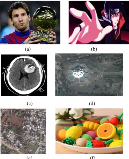
For experimental result we have considered varieties of test image which include image taken in indoor as well as out door. Also we included satellite and medical image for image registration using the proposed method. Some of the source images are shown in figure 3.
(a) (b)
(c) (d)
(e) (f)
Fig 3. Set of Test Images with dimension (a) 697x419 (b) 697x419 (c) 430x503 (d) 567x407 (e) 479x479 (f) 434x350
Input Source
Extract Random Blocks Start
Evaluate DWT
Input Target Image
Evaluate DWT
Evaluate RMSE
Initialize pbest and gbest
Calculate Velocity
Update Particle Position
Calculate Fitness Value of New Population
Current Fitness better than pbest
Keep previous pbest Update to new pbest
Update gbest value
Maximum
Iteration
Show Registered Image
Start No
No
Yes
The source images are shown in figure 3 are specified with their dimension. The corresponding target images are given in figure4.
(a) (b) (c)
(d) (e) (f) Fig 4. Set of Target Images
In the execution of program we basically have taken in average 50 populations and 150 iterations to execute the operation. The source images are of different in size.
(a) (b) Fig 5. (a) Output for ‘messi’ (b) performance plot
The result shows the registered image as well as it show a performance plot. The performance plot represents the no of iteration in x axis and fitness values in y axis. As we have considered the solution to be a minimization problem so the performance plots show the decrement. The experimental results shown in figure 5, 6,7, 8 and 9.
(a)
(b)
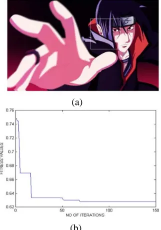
Fig 6. (a) Output for ‘cartoon’ (b) performance plot
Most of the cases we got the output with in 50 iterations, but some of the cases where target image quiet similar in characteristics with background, then it take little more iteration to converge as shown in figure 5 and 6.
(a) (b) Fig 7. (a) Output for ‘brain’ (b) performance plot
(a) (b) Fig 8. (a) Output for ‘satellite’ (b) performance plot
(a)
(b)
Fig 9. (a) Output for ‘fruits’ (b) performance plot
Figure 7, 8 and 9 shows the results with the performance plot that showing the convergence with in 50 iterations. The convergence result also depends on dimension of source image.
0 50 100 150
0 0.1 0.2 0.3 0.4 0.5 0.6 0.7
NO OF ITERATIONS
F
IT
N
ES
S VA
L
U
ES
0 50 100 150
0 0.1 0.2 0.3 0.4 0.5 0.6 0.7
NO OF ITERATIONS
F
IT
N
ESS
VAL
U
VI. CONCLUSION
In this paper, we have put a effective algorithm for Image Registration which uses Discrete Wavelet Transform and particle swarm optimization. The algorithms works with the idea of extracting sub-images from the source images and find DWT coefficients that compared with DWT coefficients of target images, which leads to a optimization problem. Then PSO effectively optimizes the convergence to get the registered image. The image registration method of this paper is applied on various types of images. Experimental results on various images in image registration shows that transparently overlapping source image with the extracted interest point area computed using DWT PSO provides an easy and efficient way of image registration.
In future we have planned to extend this work for APSO and CPSO and have a comparative analysis between the performances; also we plan to use some other feature extraction technique to improve the accuracy of result.
REFERENCE
[1]. Ruhani B.Karani Dr.Tanuja K.Sarode “ Image Registration using Discrete Cosine Transform and Normalized Cross Correlation” International Conference & Workshop on Recent Trends in Technology, (TCET) 2012.
[2]. Barbara Zitova an d Jan Flusser “Image registrationmethods: a survey” Received 9 November 2001.
[3]. Gang Hong, Yun Zhang “Combination of Feature-based and Area- based Image Registration Technique for High Resolution Remote Sensing Image” ieee international conference on Geoscience and Remote Sensing Symposium, 2007 .
[4]. M. Auer, P. Regitnig, and G. A. Holzapfel, “An automatic non rigid registration for stained histological sections,” IEEE Trans. Image Process.,vol. 14, no. 4, pp. 475–486, Apr. 2005.
[5]. Hongjun Jia, Guorong Wu, Qian Wang, Minjeong Kim, and Dinggang Shen “Itree: fast and accurate image registration based on the combinative and incremental tree” international conference on Biomedical Imaging: From Nano to Macro, 2011 .
[6]. Ronald W. K. So and Albert C. S. Chung “Multi-level non-rigid image registration using graph-cuts”ieee international conference on Acoustics, Speech and Signal Processing, 2009.
[7]. Dongjin Kwon, “Rolled Fingerprint Construction Using MRF-Based Nonrigid Image Registration”, ieee transactions on image processing, vol. 19, no. 12, december 2010
[8]. M. Clerc, J. Kennedy, “The particle swarm-explosion, stability, and convergence in a multidimensional complex space,” IEEE Trans. Evol. Comput., vol. 6, no. 1, pp. 58-73, Feb. 2002.
[9]. Manjusha Deshmukh ,Udhav Bhosle “A SURVEY OF IMAGE REGISTRATION”.
[10].Dr. H.B Kekre, Ruhani B.Karani ,Dr.Tanuja K.Sarode “2D Satellite Image Registration Using Transform Based and Correlation Based Methods” International Journal of Advanced Computer Science and Applications, Vol. 3, No. 5, 2011.
[11].Vilas H Gaidhane ,Yogesh V Hote and Vijander Singh “An efficient similarity measure technique for medical image registration” Sa¯dhana¯ Vol. 37, Part 6, December 2012, pp. 709–721._c Indian Academy of Sciences
[12].Nemir Al-Azzawi , Wan Ahmed K. Wan Abdullah “ MRI Monomodal Feature-Based Registration Based on the Efficiency of Multiresolution Representation and Mutual Information” American Journal of Biomedical Engineering 2012,2(3): 98-104.
[13].Apurba Gorai , Ashish Ghosh “Gray-level Image Enhancement By Particle Swarm Optimization” 2009 World Congress on Nature & Biologically Inspired Computing.
[14].Mei Jiansheng , Li Sukang1 and Tan Xiaomei “A Digital Watermarking Algorithm Based On DCT and DWT” Proceedings of the 2009 International Symposium on Web Information Systems and Applications (WISA’09) Nanchang, P. R. China, May 22-24, 2009, pp. 104-107
[15].Rabab M. Ramadan and Rehab F. Abdel – Kader “Face Recognition Using Particle Swarm Optimization-Based Selected Features” International Journal of Signal Processing, Image Processing and Pattern Recognition Vol. 2, No. 2, June 2009.
[16].J. Kennedy and R. C. Eberhart, Particle swarm optimization, in: Proc. of IEEE International Conference on Neural Networks, Piscataway, NJ. pp. 1942-1948 (1995).