Available online: https://edupediapublications.org/journals/index.php/IJR/
P a g e
|
492
Fuzzy Based Modulation and Control of Transformerless Unified
Power Flow Controller
Vaddi Ramu
1, Kurakula Vimala Kumar
2, Thalluru Anil Kumar
31
M.Tech Student,
2Assistant Professor,
3Professor
1,2Dept. of EEE, JNTUA College of Engineering, Pulivendhula, Andhrapradesh, India 3Dept. of EEE, CVSR College of Engineering, Hyderabad, Telangana, India
Abstract
Presently a day's FACTS gadgets are utilized to control the flow of power, to expand the transmission limit and to enhance the security of the power system. A standout amongst the most regularly utilized FACTS gadgets is Unified Power Flow Controller (UPFC). Adjustment and control strategy for the new transformerless UPFC is proposed in this paper. To defeat this issue, a transformerless UPFC in light of a creative design of two course multilevel inverters has been proposed. The traditional UPFC may substance of two consecutive associated inverters which required massive and regularly convoluted crisscross transformers for disconnection and achieving high power rating with wanted voltage waveforms. The new UPFC offers different merits over the conventional innovation, for example, light weight, transformerless, ease, high effectiveness and furthermore quick unique reaction. From this, the limit of UPFC is seen by utilizing diverse control components in light of fluffy rationale controllers (FLC) in this examination. UPFC on controlling the flow of power and the viability of controllers on the performance of UPFC is utilized to recreate UPFC display and to make the FLC.
Keywords: FACTS, Fuzzy Logic Controller, UPFC
1.
Introduction
The unified power flow controller (UPFC) can control, at the same time or specifically, every one of the parameters influencing power flow in the transmission line (i.e., voltage extent, impedance, and stage edge) [1]– [3]. The customary UPFC has been put into a few down to earth applications [4]– [6],which has the accompanying highlights: 1) the two inverters share a similar dc connect; 2) the two inverters need to trade genuine power with each other and the transmission line; 3) a transformer must be utilized as an interface between the transmission line and every inverter. Furthermore, any utility-scale UPFC requires two high-voltage, high-power (from a few MVA to several MVA) inverters. This high-voltage, high-power inverters need to utilize massive and confused crisscross transformers to achieve their required VA evaluations and wanted voltage waveforms. The crisscross transformers are: 1) exceptionally costly (30– 40% of aggregate system cost); 2) lossy (half of the aggregate power misfortunes); 3) cumbersome (40% of system land region and 90% of the system weight); and 4) inclined to disappointment [7]. In addition, the crisscross transformer based UPFCs are still too moderate in powerful
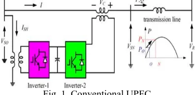
reaction because of substantial time consistent of charging inductance over protection and stance control challenges in view of transformer immersion, polarizing current, and voltage surge [8]. As of late, there are two new UPFC structures under scrutiny: 1) the network converter-based UPFC [9]– [11] and 2) appropriated power-flow controller (DPFC) got from the regular UPFC [12]. The ordinary UPFC comprises of two consecutive associated voltage source inverters that offer a typical dc connect, as appeared in Fig. 1. The infused arrangement voltage from inverter-2 can be at any point as for the line current, which gives finish adaptability and controllability to control both dynamic and receptive power flows over the transmission line.
Fig. 1. Conventional UPFC
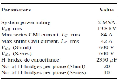
The first uses the grid converter supplanting the consecutive inverter to take out the dc capacitor with air conditioning capacitor on one side of the lattice converter. The DPFC utilizes many disseminated arrangement inverters coupled to the transmission line through single-turn transformers, and the regular dc connect between the shunt and arrangement inverters is dispensed with. To dispense with the transformer totally, another transformerless UPFC in light of a creative design of two CMIs has been proposed in [13]. The system arrangement is appeared in Fig. 2(a) and fundamental system parameters for a 13.8-kV/2-MVAprototype (target system) is appeared in Table I. As appeared in Fig. 2(a), the transformerless UPFC comprises of two CMIs, one is arrangement CMI, which is specifically associated in arrangement with the transmission line; while the other is shunt CMI, which is associated in parallel to the sending end after arrangement CMI.
(b)
Fig. 2 New transformerless UFPC (a) System configuration of transformerless UPFC (b) One phase of the cascaded multilevel inverter. Each CMI is made out of a progression of fell H-connect modules as appeared in Fig. 2(b). The transformerless UPFC has critical points of interest over the conventional UPFC, for example, very particular structure, light weight, high proficiency, high dependability, ease, and a quick unique reaction.
Table I
Main system parameters for 13.8-kV
All things considered, there are still difficulties for the adjustment and control of this new UPFC: 1) UPFC power flow control, for example, voltage direction, line impedance remuneration, stage moving or concurrent control of voltage, impedance, and stage edge, consequently accomplishing freely control both the dynamic and receptive power flowin the line; 2) dc capacitor voltage adjust control for H-extensions of both arrangement and shunt CMIs; 3) regulation of the CMI for low aggregate symphonious bending (THD) of yield voltage and low exchanging misfortune; 4) quick system dynamic reaction.
2.
Operation Principle
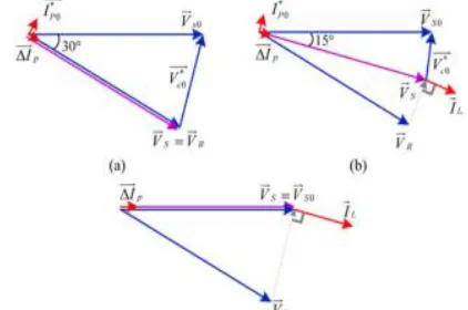
Fig. 3 shows the phasor diagram of the transformerless UPFC, where VSO and VR are the original sending-end and receiving-end voltage, respectively.
Fig. 3 Phasor diagram of the transformerless UPFC
Here, VSO is lined up with genuine hub, which implies stage edge of VSO is zero. The arrangement CMI is controlled to create a coveted voltage VC for acquiring the new sending-end voltage VS, which thus, controls dynamic and responsive power flows over the transmission line. The nitty gritty working rule of the transformerless UPFC can be detailed as takes after. With alluding to Figs. 2 and 3, the transmitted dynamic power P and receptive power Q over the line with the transformer-less UPFC can be communicated as
where image ∗ speaks to the conjugate of an unpredictable
number; δ0 is the stage edge of the less than desirable end voltage VR; δ is the stage edge of the arrangement CMI infused voltage VC ; XL is the proportionate transmission line impedance. The first dynamic and responsive powers, P0 and Q0 with the uncompensated system (without the UPFC, or VC = 0) are
(2)
The net differences between the original (without the UPFC) powers expressed in (2) and the new (with the UPFC) powers in (1) are the controllable active and reactive powers, PC and QC by the transformerless UPFC, which can be expressed as
δ δ
δ δ (3)
Therefore, we can rewrite (1) as
δ δ δ
δ δ δ
(4)
Available online: https://edupediapublications.org/journals/index.php/IJR/
P a g e
|
494
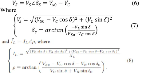
(5) Once the series CMI injected voltage V C is decided by (5), the new sending-end voltage V S and the transmission line current will be decided accordingly
(6) Where
(7)
Next, the shunt CMI infuses current IP to decouple the arrangement CMI current IC from the line current IL . In such a way, zero dynamic power trade to both arrangement and shunt CMIs can be accomplished, making it conceivable to apply the CMI with drifting capacitors to the proposed transformerless UPFC. In this manner, we have
(9)
It means the series CMI current IC and the shunt CMI current IP need to be perpendicular to their voltages V C and V S , respectively, as illustrated in Fig. 3. With the geometrical relationship of the voltages and currents in Fig. 3, the shunt CMI output current can be calculated as
(10)
Where
(11)
In synopsis, there are two basic strides for the operation of UPFC: 1) estimation of infused voltage VC for arrangement CMI as indicated by dynamic/responsive power summon over the transmission line communicated in (5), and (2) computation of infused current IP for shunt CMI from (10) and (11) to ensure zero dynamic power into both arrangement and shunt CMIs.
2.1.Fundamental Frequency Modulation (FFM) or CMIS
Before setting out on advancement of UPFC control, the balance procedure for CMIs is presented first. When all is said in done, the balance for CMIs can be classed into two fundamental classifications: 1) FFM and 2) transporter based high-recurrence beat width adjustment (PWM) . Contrasted with the bearer based high-recurrence PWM, the FFM has much lower exchanging misfortune, making it appealing for the transmission-level UPFC and other voltage high-power applications.
2.2.Optimization of Switching Angles for Minimum THD
Fig. 4 shows the operation principle of traditional FFM, where phase a output voltage of an 11-level CMI is shown as an example.
Fig. 4 Operation principle of FFM
The Fourier series expansion of the CMI output voltage shown in Fig. 4 is
(12) where n is consonant number, s is the aggregate number of H-connect modules, and αk speaks to the exchanging plot for the kth H-connect module. Hence, all triplen sounds will be disregarded for voltage THD estimation which at that point can be communicated as
(13)
Basically, (13) gives an objective function to be minimized, with the following two constraints:
(14)
And
(15)
The corresponding results have been shown in Fig. 5.
Fig. 5 Minimum THD versus number of H-bridge modules Also, an elective flow lining of FFM could be the "base weighted aggregate sounds contortion (WTHD)." The WTHD accomplishes the base current THD for inductive burdens (i.e., straightforwardly enhanced for best power quality), which is favored for application where current bending is of intrigue. In such a case, the target work in (13) ought to be changed to
As shown in Table I, for the 13.8-kV/2-MVA system, the number of H-bridges for shunt CMI is ten and the number of H-bridges for series CMI is 20.
(a)
(b)
Fig. 6 FFM with total 20 H-bridges. (a)Output voltage and current (41 levels) and (b) output voltage of each H-bridge The corresponding optimized switching angles for this case are given in Table II.
Table II: switching angles for the case mi = 1
In rundown, contrasted with transporter based high-recurrence PWM plot, the CMIs with FFM have the accompanying highlights:
1) FFM has much lower exchanging misfortune, in this manner higher productivity;
2) with high number of H-connect modules, yield voltage could be near sinusoidal, and greatly low THD (e.g., 0.85%) could be accomplished with no additional channels;
3) it is remarkable that FFM does not really mean moderate dynamic reaction. With high-recurrence testing, FFM can likewise accomplish quick unique reaction, e.g., <10 ms, which will be talked about and tentatively checked in the following area.
2.3. Analysis of Capacitor Charge of H-Bridges
Capacitor charge of H-extensions will be contemplated in light of two layers: 1) first layer is general capacitor charge, which means the aggregate capacitor charge of all H-scaffolds of any of three stages; 2) the other layer is singular capacitor charge, which means the capacitor charge of every H-connect. The general dynamic power flow of this stage from air conditioning side into dc capacitors can be
(17)
where and are RMS estimations of CMI yield stage voltage and current, separately, and θ is the stage point between yield voltage and current. Be that as it may, if the stage point θ is littler than 90°, indicated as , the general dc capacitor voltage could be adjusted if
(18)
where is the aggregate power loss of exchanging
gadgets and capacitors of one stage. On the opposite side, with the moved stage angle , the individual capacitor charge for kth H-connect, Ck more than one central period is
(19)
where k = 1, 2, . . . , s. In (19), the whole modules in a similar stage will have same load current Io and stage point move Δθ. (19) demonstrates the very extraordinary individual capacitor charge because of the unequal obligation cycles of H-connect modules. Fig. 7 outlines the capacitor charges of 20 shunt H spans with relating exchanging points given in Table II.
Fig. 7 Capacitor charge of 20 H-bridge modules with FFM
3.
Power Flow And Dc-Link Voltage Control Of
Transformerless UPSC
3.1.
Dynamic Models of UPFC SystemTo plan the vector-situated control for the proposed transformerless UPFC with thinking about both enduring state and dynamic performance, the dynamic modules are vital. The models depend on synchronous (dq) reference outline. The stage edge of unique sending-end voltage Vs0 is gotten from an advanced stage bolted circle, which is utilized for abc to dq transformation. The dynamic models for the entire system appeared in Fig. 2(a) will be separated into a few sections. Initially, we can get the dynamic model from the new sending-end transport to accepting end transport
(20)
Since the new sending-end voltage vs is equal to original sending-end voltage vs0 minus series CMI injected voltage vc , thus we have
Available online: https://edupediapublications.org/journals/index.php/IJR/
P a g e
|
496
Furthermore, the model from the new sending-end to shunt CMI is
(22)
3.2.Power Flow and Overall DC Voltage Control
Fig. 8(a) shows the overall control system, which is divided into three stages, i.e., stage I to stage III.
Stage I: the calculation from P∗/Q∗ tand I ∗ p0.
(a)
Fig. 8. Control system for transformerless UPFC. (a) Overall control diagram for both power flow and dc capacitor
voltage control
As specified some time recently, the V ∗ C0 is the voltage reference for arrangement CMI, which is created by the transmission line power charge as given in (5), while I * PO current reference for shunt CMI, which is utilized to keep zero dynamic power for both CMIs as given in (10), (11). Note that as opposed to computing V * C0 specifically from (5), an elective way is appeared in Fig. 8(b). Here, the line current reference I∗ Ld/I∗ Lq is figured out of the P∗/Q∗ reference, at that point the d-and q-pivot parts of arrangement voltage Vcod , V ∗ C0q are computed by (23), where the dynamic model of (20) is incorporated.
Stage II: general dc-connect voltage direction. With the V ∗ C0 and I ∗ p0 given in arrange I, the dc-connect voltage can't be kept up because of the accompanying three fundamental reasons: 1) the CMIs dependably have a power misfortune, 2) the figuring mistake caused by the parameter deviations, 3) the blunder amongst reference and genuine yield. Keeping in mind the end goal to control dc-interface voltage with better vigor, two factors ΔVC and ΔIP were presented for the autonomous dc-connect voltage direction of arrangement CMI and shunt CMI, separately, as appeared in Fig. 8(a).
(b)
(c)
Fig. 8. Control system for transformerless UPFC (b) nitty gritty estimation from P ∗/Q∗ to V ∗ C 0 and I ∗ p 0 , and (c)
current shut circle control for shunt CMI.
Stage III: voltage and current age for arrangement and shunt CMI .While for shunt CMI, decoupling input current control is utilized to control yield current to take after the reference current I ∗ P , as appeared in Fig. 8(c) .
3.3.Individual DC Control and Phase Balance Control
Usually, the dc capacitor voltage balance control for CMIs adopts hierarchical control structure, e.g., an outer control loop and an inner control loop.
Fig. 9. Three-phase separated overall dc voltage control for series CMI, considering capacitor-voltage unbalance
between the three phases.
4.
Fuzzy Logic Controller
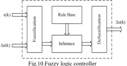
In FLC, essential control activity is dictated by an arrangement of semantic principles. These principles are dictated by the system. Since the numerical factors are changed over into etymological factors, scientific displaying of the system isn't required in FC.
Fig.10.Fuzzy logic controller
TABLE III: Fuzzy Rules
Fuzzification: Enrollment work esteems are doled out to the phonetic factors, utilizing seven fluffy subsets: NB (Negative Big), NM (Negative Medium), NS (Negative Small), ZE (Zero), PS (Positive Small), PM (Positive Medium), and PB (Positive Big). The estimation of information mistake and change in blunder are standardized by an info scaling factor. In this system the information scaling factor has been planned with the end goal that info esteems are between - 1 and +1. The triangular state of the enrollment capacity of this game plan presumes that for a specific E(k) contribution there is just a single prevailing fluffy subset. The information mistake for the FLC is given as
E(k) =
(23)
CE(k) = E(k) – E(k-1) (24)
Inference Method: A few organization techniques, for example, Max– Min and Max-Dot have been proposed in the writing. In this paper Min technique is utilized. The yield participation capacity of each manage is given by the base administrator and most extreme administrator.
Defuzzification: As a plant as a rule requires a non-fluffy estimation of control, a defuzzification organize is required. To figure the yield of the FLC, „height‟ strategy is utilized and the FLC yield alters the control yield. Further, the yield of FLC controls the switch in the inverter. In UPQC, the dynamic power, receptive power, terminal voltage of the line and capacitor voltage are required to be kept up. To accomplish this, the participation elements of FC are: blunder, change in mistake and yield
The set of FC rules are derived from
u=-[α E + (1-α)*C] (25)
(a)
(b)
Fig 11 (a) input error as membership functions (b) change as error membership functions
Fig.2 output variable Membership functions
Where α is self-flexible factor which can direct the entire operation. E is the mistake of the system, C is the adjustment in blunder and u is the control variable.
5.
Simulation Results
To validate the functionality of the transformerless UPFC system with proposed modulation and control algorithm
5.1.UPFC Operation - Phase Shifting
Three working focuses with various moved stages are considered as appeared in Fig. 13(a) case A1: 30°, (b) case A2: 15°, and (c) case A3: 0°. Every one of the three stage moving cases (case A1 to case A3) have been tried and relating test comes about are appeared in Figs. 14– 17.
Fig. 13. UPFC operating points with different phase shifting: (a) case A1: 30°, (b) case A2: 15°, and (c) case A3: 0°. Some discussions about the test results are given as follows: Fig. 14 shows the simulation waveforms of UPFC operating from case A1 to case A2 (Phase shifting 30° to 15°). In addition, Fig. 14 also shows that the current smoothly and quickly raised from zero to 7A, when the operating point is changed from case A1 to A2.
Available online: https://edupediapublications.org/journals/index.php/IJR/
P a g e
|
498
(b)
Fig. 14. Simulation waveforms of UPFC operating from case A1 to case A2 (phase shifting 30° to 15°): (a) shunt CMI line voltage VP ab , shunt CMI phase current IP a , and
line current ILa , and (b) the zoomed in waveforms Similarly, the simulation waveforms of UPFC operating from case A2 to case A3 (Phase shifting 15° to 0°) are shown in Fig. 15.
(a)
(b)
Fig. 15. Simulation waveforms of UPFC operating from case A2 to case A3 (phase shifting 15° to 0°): (a) shunt CMI
phase voltage VP a , VP b and line current ILa , ILb , ILc , and (b) line current ILa and shunt CMI line voltage VP ab . Fig. 16 shows the measured dynamic response with operating point changing from case A2 to case A3, where the current amplitude would change from 7 to 14 A.
Fig. 16. Measured dynamic response with operating point changing from case A2 to case A3 (phase shifting 15° to 0°). Fig. 17 shows the simulation results of dc capacitor voltage of both series and shunt CMIs when operating from case A2 to case A3, where top three waveforms correspond to average dc voltage of each phase, and bottom one corresponds to average dc voltage of all three phases.
(a)
(b)
Fig. 17. Simulation results of dc capacitor voltage of series and shunt CMIs, from case A2 to case A3 (phase shifting 15° to 0°): (a) dc capacitor voltage of series CMI and (b) dc
capacitor voltage of shunt CMI.
UPFC Operation - Line Impedance Compensation
Fig. 18 indicates three operation focuses with line impedance pay, (a) caseB1: unique line impedance without remuneration is equivalent to 0.5 p.u., (b) case B2: equal line impedance after pay is equivalent to 1 p.u., and (c) case B3: proportionate line impedance after pay is equivalent to endlessness.
(a)
(b)
(c)
Fig. 18. UPFC operating points with line impedance compensation: (a) case B1: original line impedance without
compensation = 0.5 p.u., (b) case B2: equivalent line impedance after compensation = 1 p.u., and (c) case B3:
(a)
(b)
Fig. 19. Simulation waveforms of UPFC operating from case B1 to case B2 (line impedance from original 0.5 p.u. without compensation to 1 p.u. after compensation): (a) line
current ILa and shunt CMI line voltage VP ab , (b) line current ILa and series CMI phase voltage VC a .
Fig. 20. Measured dynamic response with operating point changing from case B1 to case B2 (line impedance from
original 0.5 p.u. without compensation to 1 p.u. after compensation).
UPFC Operation - Independent P/Q Control
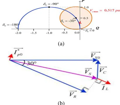
The blue curve in Fig. 21(a) shows the transmittable active power P and receiving-end reactive power Q versus receiving end voltage phase angle δ0 in the uncompensated system, where original sending-end voltage is oriented to 0°.
(a)
(b)
Fig. 21. Independent P/Q control: (a) control region of the attainable active power P and receiving-end reactive power
Q with series CMI voltage = 0.517 p.u. and δ0= − 30◦, (b) case C1: P = 0.25, Q = 0.
Fig. 22 shows the corresponding experimental waveforms, (a) line current ILa and shunt CMI line voltage VP ab, and (b) line current ILa and series CMI phase voltage VCa.
(a)
(b)
Fig. 22. Simulation waveforms of UPFC operation case C1: P = 0.25, Q = 0: (a) line current ILa and shunt CMI line voltage VP ab , and (b) line current ILa and series CMI
phase voltage VC a .
6.
Conclusion
As per this paper display an adjustment and control method for the transformer considerably less UPFC, which has the consequent highlights: All UPFC capacities, together with voltage law, line impedance repayment, fragment exchanging or synchronous control of voltage, impedance, and area mentality, in this way accomplishing fair vivacious and responsive power float oversee over the transmission line; FFM of the CMI for to a great degree low THD of yield voltage, low exchanging misfortune and intemperate performance; Dc capacitor voltage adjusting control for both gathering and shunt CMIs; Fast unique response (<10 ms). The fluffy controller is that the pleasant relevant for the human decision making instrument, conferring the operation of AN electronic system with choices of experts. The FLC consolidates of 3 sections: fuzzification, impedance motor and defuzzification. The transformerless UPFC with proposed tweak and control might be mounted wherever in the lattice to expand/flowline power transmission over the overall matrices, diminish transmission blockage and empower high entrance of inexhaustible power assets.
7.
References
[1]N. G. Hingorani and L. Gyugyi, Understanding Facts: Concept and Technology of Flexible AC Transmission Systems. Piscataway, NJ, USA: IEEE Press, 2000.
[2] L.Gyugyi, C.D. Schauder, S. L.Williams, T. R. Rietman,D. R. Torgerson, andA. Edris, "The unified power flow controller:A new way to deal with power transmission control," IEEE Trans. Power Del., vol. 10, no. 2, pp. 1085– 1097, Apr. 1995.
Available online: https://edupediapublications.org/journals/index.php/IJR/
P a g e
|
500
[4] C. D. Schauder, L. Gyugyi, M. R. Lund, D. M. Hamai, T. R. Rietman, D. R. Torgerson, and A. Edris, "Operation of the unified power flow controller (UPFC) under reasonable imperatives," IEEE Trans. Power Del., vol. 13, no. 2, pp. 630– 639, Apr. 1998. [5] S. Y. Kim, J. S. Yoon, B. H. Chang, and D. H. Baek, "The operation experience of KEPCO UPFC," in Proc. eighth Int. Conf. Electr. Mach. Syst., 2005, pp. 2502– 2505.
[6] C. Schauder, E. Stacey, M. Lund, L. Gyugyi, L. Kovalsky, A. Keri, A. Mehraban, and A. Edris, "AEP UPFC
venture: Installation,
commissioningandoperationofthe160MVASTATCOM(phas eI),"IEEETrans. Power Del., vol. 13, no. 4, pp. 1530– 1535, Oct. 1998.
[7] K. Sano and M. Takasaki, "A transformerless D-STATCOM in light of a multivoltage course converter requiring no DC sources," IEEE Trans. Power Electron., vol. 27, no. 6, pp. 2783– 2795, Jun. 2012.
[8] B. A. Renz, A. Keri, A. S. Mehraban, C. Schauder, E.Stacey, L.Kovalsky, L.Gyugyi, and A.Edris,"AE Punified power flow controller performance," IEEE Trans. Power Del., vol. 14, no. 4, pp. 1374– 1381, Oct. 1999.
[9] J. Monteiro, J. F. Silva, S. F. Pinto, and J. Palma, "Network converter-based unified power-flow controllers: Advanced direct power control strategy," IEEE Trans. Power Del., vol. 26, no. 1, pp. 420– 430, Jan.2011. [10]J.Monteiro,J.F.Silva,S.F.Pinto,andJ.Palma,"Linearandsli ding-mode control outline for framework converter-based unified power flow controllers," IEEE Trans. Power Electron., vol. 29, no. 7, pp. 3357– 3367, Jul. 2014.
[11] A. Dasgupta, P. Tripathy, and P. S. Sensarma, "Framework converter as UPFC for transmission line pay," in Proc. Int. Conf. Power Electron., Oct. 2007, pp. 1050– 1055.
[12] Z. Yuan, S. W. H. de Haan, J. B. Ferreira, and D. Cvoric, "A FACTS gadget: Distributed power-flow controller (DPFC)," IEEE Trans. Power Electron., vol. 25, no. 10, pp. 2564– 2572, Oct. 2010.