R E S E A R C H
Open Access
Multi-functional MIMO communication in
multi-hop cellular systems
Sandra Roger
*, Daniel Calabuig, Jose F Monserrat and Narcis Cardona
Abstract
In the context of multi-hop cellular communications, user equipment devices (UEs) with relaying capabilities provide a virtual infrastructure that can enhance the cell spectral efficiency. UE relays, which are generally transparent to the destination user and lack channel state information, mainly operate in an open-loop mode. Most open-loop
transmission techniques for relaying are based on orthogonal space-time block coding (OSTBC), which offers a good trade-off between performance and complexity. In this paper, we consider the concept of multi-functional
multiple-input multiple-output (MIMO) transmission, which combines OSTBC with beamforming techniques. This concept is applied to networks with multiple relays, which can offer a high number of antennas to implement multi-functional MIMO techniques. The proposed schemes are shown to reduce the bit error rate of the destination user with respect to a direct transmission from the base station (BS). Furthermore, the multi-functional setup exhibits better performance than conventional OSTBC at high transmission rates.
Keywords: D2D relaying; MIMO; DSTC
1 Introduction
Cellular communication systems are in continuous evo-lution to satisfy the highly increasing user demands. The future information society is expected to support very high data rates in dense crowds of users and in very het-erogeneous scenarios. This challenging requirement has triggered the research activities towards the design of fifth generation mobile networks (5G), where the European Union project METIS is playing a key role. So far, the METIS consortium has identified a set of scenarios and requirements to be addressed by 5G systems. In partic-ular, it is especially relevant in the need for providing ten to one hundred times higher average user data rate per cell than today’s cellular systems [1]. It is known that the traditional cellular architecture provides a non-homogeneous user rate distribution within the coverage area. This is mainly due to the fact that cell-edge users generally have lower signal-to-noise and interference ratio (SINR) levels than those located closer (in terms of radio signals) to the base station (BS). This drawback can be somehow solved by increasing the BS density through
*Correspondence: [email protected]
Institute of Telecommunications and Multimedia Applications, Universitat Politècnica de València, Camino de Vera s/n, 8G Building, 4th floor, 46022 Valencia, Spain
smaller cells. However, this solution involves large infras-tructure costs and operating expenses. A different enabler to increase the data rate of worst-case users consists in the integration of relaying techniques into cellular sys-tems, mainly using fixed infrastructure-based relays. This strategy was adopted by the LTE-Advanced standard [2]. Using relaying techniques, the frequent non-line-of-sight links with low SINR at the user equipment devices (UEs) are replaced by several multi-hop links of better qual-ity. This new network paradigm improves system capacity [3]. In addition to fixed relaying, mobile relaying can be used to enhance the network performance by providing a low-cost virtual infrastructure. Although mobile relays require higher management complexity than fixed relays, they are more dynamic and can be adapted to continu-ous changes in the network. In this area, the enhanced computing capabilities of UEs are offering new opportuni-ties for device-to-device (D2D) mobile relaying in cellular networks [4,5]. As shown in [5] through system evalua-tions, the cell-edge user throughput can be increased to 300% using idle UEs as relays. Furthermore, recent experi-mental evaluations of the cellular multi-hop concept using commercial cellular networks proved the interest of this technology to extend the cell coverage, to increase the
quality of service at large distances to the BS, and, also, to reduce the energy consumption [3].
One of the key technologies to increase the average user data rate is the use of multiple-input multiple-output (MIMO) techniques. Wireless relay networks, either fixed or mobile, can exploit the performance advantages of MIMO technology by setting up a distributed MIMO sys-tem where the relays form a virtual antenna array (AA). In a MIMO relay network with perfect channel state infor-mation (CSI), the capacity increases logarithmically with the number of relays, for a fixed SINR and a fixed num-ber of antennas at the source, relays, and destination [6]. Achieving the capacity upper bound of this system, how-ever, requires full cooperation among the relays to allow for joint data decoding as in MIMO point-to-point sys-tems. Unfortunately, in practical cellular systems with UE relays, the aforementioned capacity upper bound can-not be always reached. First, cooperation among the UE relays involves extra control information, which penal-izes the data rate. Besides, relays are often transparent to the destination UE and, thus, they do not have a cell-specific reference signal for channel estimation. Due to the absence of CSI on the forward channel and to the inherent mobility of UEs, such type of UE relays generally operates in open-loop mode (i.e. without CSI at the transmitter). In addition to the limitations in terms of CSI knowledge and unlike infrastructure-based relaying, D2D relaying is also limited by practical constraints. Of particular importance are the limited computing capabilities and battery life of UEs, as well as the desired non-cooperation among the UE relays.
The aforementioned limitations of the transmission through the D2D link motivate the research for open-loop D2D relaying designs. As known from MIMO point-to-point systems, space-time codes (STCs) are open-loop transmission techniques that provide diversity gain by using multiple transmitting antennas and multiple time slots to deliver a block of data. Tarokh et al. [7] proposed orthogonal space-time block codes (OSTBCs), which can be encoded and decoded with linear complexity. The well-known Alamouti code is a particular OSTBC design for two antennas that provides full code rate (rate 1), meaning that the required number of time slots matches the num-ber of symbols transmitted within a block. However, there are no complex OSTBC designs with full rate for more than two antennas. In fact, the maximum possible code rate is equal to 3/4 [8]. Alternative code designs include the quasi-orthogonal space-time block codes (QOST-BCs) proposed by Jafarkhani [9], which requires as many time slots as antennas but a more complex receiver than OSTBC. In fact, the four-antenna QOSTBC scheme pro-posed in [9] was shown to exhibit better performance results than the rate-1/2 four-antenna OSTBC in [7] for low SNR values. Nguyen et al. [10] considered group-wise
STCs for a trade-off between performance and complex-ity, where the transmit antennas are divided into multiple groups or layers that transmit smaller-size STC symbol blocks. As a further step, Hanzo et al. [11] proposed a gen-eralized multi-functional MIMO system, which combines the benefits of group-wise STC with per-layer beamform-ing to trade diversity and array gains, showbeamform-ing significant performance enhancements in MIMO point-to-point sys-tems. Furthermore, the multi-functional MIMO setup can be easily scaled with the number of antennas, which makes it especially advantageous in systems with a high number of transmit antennas, where OSTBCs have large block lengths and are not able to provide full code rates.
In the context of relay networks, OSTBCs have been extensively used in distributed STC (DSTC) designs. In this area, Laneman et al. [12] pioneered DSTC in a network with a large number of single-antenna relays. Barbarossa et al. [13] compared alternative DSTC strate-gies trading diversity gain and rate. Jing et al. also developed DSTC schemes using orthogonal and quasi-orthogonal designs [14]. Hayes et al. [15] exploited QOSTBC in a closed-loop relay network, where feedback was used to include phase rotations at the transmitter. More recent schemes, such as the one by Zou et al. [16], performed opportunistic DSTC based on the Alamouti code in a network with two UEs assisting each other. However, no extension to more than two UEs has been proposed for this approach. In general, most of these schemes did not take into account the code rate penalty experienced by OSTBCs with more than two antennas. Kim et al. [17] recently investigated several open-loop relaying strategies with UE relays but did not exploit the availability of multiple antennas at the relays. On the other hand, Fan et al. [18] considered multiple-antenna relays to implement the Alamouti code, but the multiple antennas at the relays were only used for maximum ratio combining, not to transmit a higher-dimension OSTBC.
cooperation among the UE relays, since each relay can encode a different group of symbols independently.
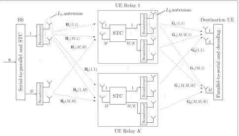
2 System model
The system model considered in this work is shown in Figure 1. We consider a MIMO relay network represent-ing the downlink communication in a srepresent-ingle-cell system from a base station (BS) withMSantennas to a destination
UE withMDantennas. The communication is assisted by K UEs acting as relay nodes. TheMS transmit antenna
elements of the BS are grouped intoMAAs withLS
ele-ments each, i.e.MS = MLS. We consider that each relay
has MR ≥ M available antennas to decode the
infor-mation sent from the MBS AAs. In order to relay the received information, the total transmit antennas at the relays are also grouped intoMAAs ofLRelements each,
such that KMR ≥ MLR. The AAs experience
indepen-dent fading and hence can provide transmit diversity. For simplicity,MD = Mis assumed. Furthermore, we
con-sider all the relays in the middle region between the BS and the destination. It is also assumed that all the relays are located at approximately the same distance from BS, equal to d, and experience independent fading but the same pathloss. Note that, with minimal modifications in the system model, the proposed scheme is also applica-ble to the case of relays with different pathlosses. The system model also includes the direct transmission from
BS to destination, which is a basic point-to-point MIMO channel, but it has not been included in Figure 1 for the sake of presentation clarity.
Since the main focus of this work is on open-loop trans-missions, we investigate here the transmission schemes combining STC and beamforming. As it will be discussed later, these transmission schemes suit well with a net-work with MIMO relays, which provides a high number of transmitting antenna elements at the relaying stage. Data transmission is performed in two phases. In phase I, the BS transmits data to the relays and destination duringT1
time slots. In phase II, the BS is silent and the relays trans-mit information to the destination duringT2time slots. When the communication starts, a block ofM indepen-dent input information symbols is serial-to-parallel con-verted into the complex-valued vectors = [s1,. . .,sM]T. The symbolssb,b = 1,. . .,M, are taken from a constel-lationof size|| = Mand hence carry log2Mcode bits each. The symbol-vectorsis then encoded using STC techniques, resulting inSS(s) ∈ CM×T1. In addition, the MAAs of LS elements each are used to provide
beam-forming gain over the components of matrix SS(s). For
the beamforming operation, a uniform linear array (ULA) is assumed, and the beamforming weights are computed based on the direction-of-arrival (DOA) of the destination UE, denoted byθD, as it was done in [11]. For simplicity,
each BS AA is represented by a single antenna with power
gain equal toL2S. It is worth noting that, in those cases when there is any mismatch between the DOA from BS to relays, denoted byθR, and the DOA from BS to destination
user, the beamforming gain at the relays will be generally
L2SR
k <L
2 S.
Focusing on the system model, in phase I, the relays use
Mout of theirMR antennas for reception. The received
signal matrix at thek-th relay,Rk ∈CM×T1,k= 1,. . .,K CM×T1 represents the complex additive white Gaussian
noise (AWGN) matrix with i.i.d. zero-mean unit-variance
elements, and αR includes the pathloss term, which
depends on the distance between the source and relays. Note that, after the beamforming operation,Hk ∈CM×M is the channel matrix containing i.i.d. zero-mean unit-variance elements, i.e. its counit-variance matrix equals IM, which describe the signal fading from each BS AA to each relay antenna [11]. As an approximation, in most of the evaluations presented in this work, we will consider that
LSRk =LS,∀k. This assumption will provide the best-case performance of the setup. Nevertheless, a short analysis of the impact ofLSRk <LSdue to DOA mismatch will be provided in Section 4.2.
At the same time during phase I, the destination receives the signal vectorYSD∈CM×T1
destination, with elements of the same statistics as Zk, the channel matrix HD ∈ CM×M contains i.i.d.
zero-mean unit-variance fading elements, andαD reflects the
pathloss for the direct link. Note that, in cases of large dis-tance between source and destination,αD ≈ 0, implying
that the direct link from BS to destination is unavailable. After phase I, each relay decodes the received signal with maximum likelihood and obtains vector ˆs, which is an estimation of the transmitted symbols. Then, the relays carry out a STC operation overˆsto obtainSR
ˆ s∈
CM×T2. As done at the BS, the relays can further include
array gains by usingLRantenna elements for
beamform-ing. Hence, the signal matrix received at the destination from theKrelays in phase II is:
YRD=LR
Here,ηRis the total transmitted power shared uniformly
by all the relays,ZRD ∈ CM×T2 represents the AWGN at
the destination, again with i.i.d. zero-mean unit-variance elements,βRincludes the pathloss from the relays to the
destination UE, and G = [G1,. . .,GK] is the channel matrix, where Gk ∈ CM×M/K contains i.i.d. elements describing the channel from the AAs of thek-th relay to each destination antenna. It is also worth noting that the beamformer design at the UE relays is not straightforward, as there is not any CSI feedback from the destination to the relays. Nevertheless, in the proposed implementation, it is assumed that the UE relays can obtain the destina-tion DOAs by monitoring the uplink sounding signals, as already done by the LTE transmission mode 7 [19]. Fur-thermore, a useful way to track changes in the DOA due to UE rotation and movement was proposed in [20], where state-of-the-art smartphone motion sensors are used for that purpose.
3 Proposed multi-functional MIMO transmission
with relays
This section provides details about the multi-functional transmitter and receiver proposed for MIMO point-to-point systems in [11]. In addition, we describe the multi-functional MIMO implementations with relays proposed in this paper. We also describe the QOSTBC scheme that will be used as a baseline for the performance evalua-tion of the group-wise STC structure within the multi-functional MIMO setup.
3.1 Multi-functional MIMO transmitter
For the description of the multi-functional MIMO scheme for point-to-point systems, the system model in Section 2 is particularized forK=0. The symbol vector to be trans-mitted, s ∈ CM, is divided intoP groups ofJ symbols. Thep-th group of symbols, denoted bysp, is encoded by a STC designed forJantennas andT1time slots, which is denoted by STCp. DuringT1time slots, the components of STCpare transmitted through theJAAs assigned to the
p-th symbol group. Finally, theLS antennas per AA are
used for beamforming to enhance the transmitted sym-bols, as described in the previous section. Note that this setup combines the three main MIMO gains: multiplex-ing gain is implicit due to the transmission of different data through each AA, coding gain is provided by the STC group-wise encoding, and beamforming gain is attained with the AAs.
The multi-functional MIMO transmitter can be imple-mented based on a variety of STC designs. If the Alamouti code is chosen for the P groups,T1 = 2 time slots are required for its transmission. The matrix that collects the STC operations for all groups is
where the column cAt, t = 1, 2, represents the signal vector jointly transmitted from the M AAs during the
t-th time slot. Results of a multi-functional MIMO
trans-mission of P = 2 Alamouti groups can be found in
[11].
3.2 Multi-functional MIMO receiver
For convenience, the channel matrixHDin (2) is split into
smaller-size matricesHp ∈ CM×J, each of them associ-ated to a STC group, i.e.HD = [H1,H2,. . .,HP]. At the destination, thePSTC groups can be efficiently decoded through group-wise successive interference cancelation following a smart order, e.g. targeting the highest-SNR groups first [11]. Starting from the detection of STC1, the
decoder computes an orthonormal basis for the left null space ofH=[H2,. . .,HP] and constructs a matrixQwith the vectors of this basis in its rows, such thatQH = 0. Then, the received signal matrix is pre-multiplied byQin order to cancel the interference suffered by STC1due to
the rest of STC groups. The symbols associated to STC1
can then be directly estimated using a conventional space-time decoder. Next, STC1is reencoded again according to
the just-obtained symbols and its contribution is extracted from the received signal. The rest of STC groups are suc-cessively decoded following the same steps. If OSTBCs are selected for each group, each STC group can be decoded with linear complexity and maximum likelihood (ML) performance.
3.3 Proposed schemes with relays
In this section, we propose two alternatives to include the multi-functional MIMO structure in the setup of Figure 1. In the proposed schemes, each STC group is directly mapped to a different relay. Hence, from now on the correspondenceP = K is assumed. The designs are differentiated, depending on the availability of the direct link.
3.3.1 Scheme with availability of the direct link
When the direct link from BS to destination is avail-able, the BS cooperates with the relays to send a certain multi-functional MIMO scheme. Considering the above-described multi-functional MIMO setup composed of
K Alamouti STC groups (4), the matrices to be trans-mitted from the BS and from the relays are constructed as SS(s) = cA1(s) and SRsˆ = cA2
ˆ
s, respectively.
Hence, T1 = 1 and T2 = 1 is required.
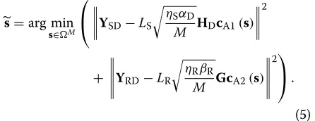
Beamform-ing is also included at the BS and relays. Note that, since the channel between BS and destination is differ-ent from the channel between relays and destination, linear processing does not guarantee maximum likeli-hood decoding as usually happens when decoding the Alamouti scheme. Therefore, the decoding of s at the destination is carried out by searching over the set of
possible transmitted symbol vectors, denoted byM, to minimize
3.3.2 Scheme without availability of the direct link
In this case, the direct link is unavailable and the relayed transmission requires more time slots for the communica-tion than the direct transmission without relays. Here, one multi-functional MIMO transmission per phase is consid-ered, i.e. the BS transmitsSS(s)=[cA1(s),cA2(s)] and the
tively. As in the scheme with availability of the direct link, beamforming at the BS and relays is also included. Note that, in this case, all the code columns go over the same channel, which allows for a simplified decoding with linear complexity at the relays and destination receivers.
3.4 Group-wise STC baseline forM=4
Note that the majority of works on open-loop D2D relay-ing are based on OSTBC schemes [12,18]. Therefore, the main alternative to the proposed multi-functional MIMO system based on group-wise STC is the use of OSTBC or QOSTBC schemes jointly designed for all the available transmitter antennas. Although previous works mainly focused on the relaying of two symbols per trans-mission block, we also evaluate the performance of the
proposed approach when M = 4 symbols per block
are relayed simultaneously. In particular, we consider the QOSTBC as a baseline to compare the group-wise STC multi-functional MIMO transmission. For convenience, the QOSTBC code matrix is included hereafter:
CQ(s)=
Although there are several options to cooperatively transmit the four columns of the QOSTBC code matrix to the destination, in this work, we focused on the coopera-tive QOSTBC scheme that achieves the best performance when the relays are located at d = 0.5. In this sense, to transmit the QOSTBC scheme when the direct link is available, the best-performing QOSTBC setup transmits
SS(s) =
cQ1(s),cQ2(s)
from the BS and, after decod-ing, the relays transmitSR
T1 = 2 and T2 = 2 in this case. On the other hand, if the direct link is unavailable, the four columns of the QOSTBC code matrix are first transmitted from BS to relays, decoded, and then retransmitted from relays to destination. In the latter scheme,T1 = 4 andT2 = 4 are
necessary to transmitSS(s)=CQ(s)andSR
ˆ s=CQ
ˆ s, respectively.
4 Performance evaluation
In this section, we evaluate the performance of the pro-posed alternatives to implement multi-functional MIMO
relaying in an exemplary setup with K ≤ 2 and
dif-ferent values of M, LS, and LR. We consider that the
distance between source and destination is normalized to 1, e.g. d is equal to 0.5 in a setup where the relays are located right in the middle of the BS-destination path. The pathloss of the source to relays links and of the relays to destination links are included in the distance-dependent terms αR = d−γ and βR = (1 − d)−γ,
respectively, whereγ is the pathloss exponent with a typ-ical value of 4 [18]. The total transmitted power from the source and from the relays is considered the same (ηS=ηR=η).
4.1 Effect of beamforming with additional antennas First, the effect of beamforming from either the BS or the relays in the multi-functional setup is evaluated. In this section, we assume that either the BS or relays have more thanMantennas and the extra available antennas can be used for beamforming. This setup is advantageous in a situation whereMS=KMRand the extra available
trans-mit antennas cannot be used to increaseMand transmit
more STC groups, due to the mismatch between the number of BS and relays antennas. As an exemplary case, a multi-functional MIMO setup composed of two
Alam-outi STC groups (K = 2,J = 2) transmittingM = 4
QPSK symbols per block is considered. Here, we assume that the direct link from BS to destination is available to transmit the first column of the codes to the destina-tion (SS(s) = cA1(s)). Then, the second column of the
multi-functional scheme is transmitted from the relays, i.e.SR
ˆ s= cA2
ˆ
s. Since four QPSK symbols are trans-mitted within two time slots, the transmission rate of this configuration is 4 bpcu.
To evaluate the effect of beamforming at relays,LS= 1
is fixed andLRis varied. Figure 2a shows the BER perfor-mance of this scheme as a function of the relays position atη= 0 dB. The direct transmission of the same scheme without relays is also included as a baseline. It can be first observed that the direct transmission is outperformed by all the relayed schemes for almost every relay position. However, when d ≥ 0.75, the direct transmission out-performs the relayed transmissions because the decoding errors at the relays are worsening the performance of phase II. Regarding the optimal relays position, it can be observed that it highly depends on the value of LR. The
optimal position is d = 0.5 when no beamforming is
included, but it isd=0.4 andd=0.2 for theLR=2 and LR = 3 cases, respectively. Hence, the higher the
beam-forming gain at the relays, the closer to the BS should the relays be located to minimize the BER. In fact, when
d ≥ 0.6, the beamforming gain at relays is useless and the quality of the link from the BS to relays is the limiting factor.
In Figure 2b, LS = 2 is considered. In this case, the relayed transmission withLS = 2 andLR = 1 only out-performs the direct transmission for 0.3 < d ≤ 0.7. The reason is that, while in the direct transmission both STC columns enjoy the beamforming gain (from the BS), in the relayed setup only one of the two STC columns does. For
d ≥ 0.75, it is again observed that the effect of decoding errors worsens the performance of the relayed transmis-sions. Finally, the scheme withLS=2 andLR=2 achieves
the best performance but, again, the beamforming gain at the relays is useless ford ≥0.6. Therefore, the additional complexity to carry out beamforming is not worth at all in setups where the relays are closer to the destination than to the BS.
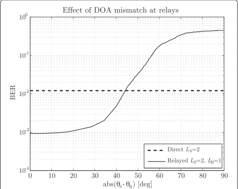
4.2 Effect of DOA mismatch
Next, we continue with the setup evaluated in Figure 2b and focus on the relayed scheme withLS=2 andLR=1 ford = 0.5. We now assume that the DOA at the relays does not match the DOA of the destination user, which causesLSRk < LS. Figure 3 shows the BER versus dif-ference betweenθRandθD. Note that the gain affecting
the relays for each difference between DOAs,LSRk, has been directly taken from the well-known beam pattern of a ULA withLS= 2 elements. It can be observed that the
BER is nearly constant for DOA differences lower than 20°, i.e. the approximationLSRk = LS,∀k, holds for relays located within 40° around the straight line from BS to destination. This means that the area with useful relays is one third of the area of a conventional sector. Thus, a suitable selection of relays can guarantee the best-case performance. Furthermore, the relayed scheme outper-forms the direct transmission for DOA differences lower than 45°, i.e. within 90° around the straight line from
Figure 3BER versus DOA mismatch for a multi-functional MIMO setup with relays located atd=0.5.
BS to destination. For higher DOA differences due to an improper relay selection, however, a direct transmission without relays is the best option.
4.3 Beamforming versus STC
In this subsection, we study the trade-off between cod-ing and array gains in the relayed multi-functional setup,
setting MS = 4,MR = 4, and d = 0.5. To this end,
we evaluate two different Alamouti-based configurations. The first one considersM= 4 and does not include any beamforming gain (LS = 1 andLR = 1). Rather, four
transmit antennas are used to sendK =2 Alamouti STC groups from the BS and relays, as in the previous sub-section. The second configuration considersM= 2 (one STC group) and uses the antennas to include beamform-ing gain at the BS and relays (LS = 2 andLR = 2). Both setups are tested with and without availability of the direct link, as described in Section 3.3. The same transmission rate is set for both schemes, working with a constellation of double bits per symbol in theM = 2 case in order to compensate the multiplexing loss.
Figure 4 shows the BER versusηcurves of the investi-gated configurations for two different transmission rates, where the rates in (a) are half the ones in (b). In Figure 4a, the Alamouti-based setup with{M = 2,LS = 2,LR = 2}
outperforms the setup with{M = 4,LS = 1,LR = 1}for η≤ −5, when the direct link is not available. Hence, at low transmitted power values, the beamforming compensates the multiplexing loss caused by transmittingM=2 sym-bols instead ofM = 4 simultaneously. Therefore, in the low SNR regime, a multi-functional scheme combining array and STC gains is more advantageous than a multi-functional scheme purely based on STC. For the case with availability of the direct link, however, there is no substan-tial enhancement due to beamforming in the BER range of interest.
Figure 4b shows the performance results of the same schemes when the transmission rate is doubled. It can be observed that combining beamforming with STC is less advantageous than only performing STC. The reason is that the beamforming gain does not compensate the increased SNR requirements of the 16-QAM constellation with respect to QPSK for the same BER objective. Hence, using the available antennas to achieve multiplexing gain is more convenient than using them for beamforming. Nevertheless, we recall that beamforming can further enhance the performance when there are extra unused antennas available for this purpose (i.e. whenMS=KMR),
as studied in Section 4.1.
4.4 Group-wise STC versus joint STC designs
Figure 4BER performance versus transmitted power of two Alamouti-based multi-functional MIMO setups.BER performance versus transmitted power of two Alamouti-based multi-functional MIMO setups withMS=4,MR=4, andd=0.5, both evaluated with and without
availability of the direct link:(a)with BPSK and QPSK,(b)with QPSK and 16 QAM.
numbers of antennas are again set toMS=4 andMR=4,
andd = 0.5 is assumed. Again, we consider the multi-functional setup based on two Alamouti STC groups (K = 2,J = 2). For this comparison,M = 4,LS = 1,
and LR = 1 are assumed in all the schemes. Since the
QOSTBC setup requires twice as many time slots as the considered group-wise scheme, a constellation of double bits per symbol is considered for the QOSTBC to make both schemes comparable in terms of transmitted rate.
Figure 5 shows the BER versusηcurves for two different transmission rates, where the rates in (a) are half the ones in (b). In Figure 5a, the QOSTBC-based setup using QPSK symbols outperforms the Alamouti-based setup using BPSK. However, the opposite happens in Figure 5b, where the multi-functional transmission based on group-wise Alamouti STC with QPSK is more advantageous than the QOSTBC with 16 QAM. Again, the reason is that a lin-ear increase in the modulation order entails a non-linlin-ear increase in the SNR to fulfill a given BER objective. For this
reason, the higher coding gain of QOSTBC does not com-pensate the use of a constellation of double bits per symbol at high transmission rates. In addition, Figure 5b reveals that the performance enhancement of the Alamouti-based multi-functional setup is higher in the relayed scheme without availability of the direct link.
5 Conclusion
This paper exploited multi-functional MIMO techniques in wireless networks with multi-antenna UE relays. Tak-ing into account the practical limitations of UE relays, as well as the general open-loop relaying operation of these devices, the combination of group-wise STC with directional beamforming was exploited in a coopera-tive manner. The results showed that beamforming at either stage can strongly enhance the performance of the multi-functional transmission, but a suitable selection of the relays is necessary to guarantee the least possible mismatch between the DOA from BS to relays and the
Figure 5BER comparison between Alamouti-based multi-functional MIMO and QOSTBC transmission.BER comparison between Alamouti-based multi-functional MIMO and QOSTBC transmission withMS=4,MR=4, andd=0.5, both evaluated with and without availability
DOA from BS to destination. The combination of beam-forming with group-wise STC is especially useful when there is a different number of available antennas at the BS and at the relays. However, including beamforming at the relays is only beneficial when the relays are closer to the BS than to the destination. On the contrary, when the relays approach the destination, the quality of the link between BS and relays is the limiting factor and the extra complexity to carry out beamforming becomes useless. By comparing a scheme only based on group-wise STC with a scheme combining group-group-wise STC and beamforming, it was shown that beamforming can com-pensate the multiplexing loss at low transmission rates. However, when the constellation sizes are increased, a multi-functional scheme only based on group-wise STC is more advantageous. Finally, the relayed transmission of a multi-functional scheme based on group-wise STC was compared with the relayed transmission of a QOSTBC jointly designed for the same total number of transmit antennas, where the QOSTBC was considered as the baseline STC setup for four antennas. At high transmis-sion rates, it was observed that group-wise STC is more advantageous than joint STC (i.e. QOSTBC).
Competing interests
The authors declare that they have no competing interests.
Acknowledgements
This work was performed in the framework of the FP7 project ICT-317669 METIS, which is partly funded by the European Union. The authors would like to acknowledge the contributions of their colleagues in METIS, although the views expressed are those of the authors and do not necessarily represent the project.
Received: 10 June 2014 Accepted: 28 October 2014 Published: 19 November 2014
References
1. B Timus, M Fallgren (eds.), D1.1: Scenarios, requirements and KPIs for 5G mobile and wireless system. Project deliverable, ICT-317669-METIS (2013) 2. K Zheng, B Fan, Z Ma, G Liu, X Shen, W Wang, Multihop cellular networks
toward LTE-advanced. IEEE Veh. Tech. Mag.4(3), 40–47 (2009) 3. J Gozalvez, B Coll-Perales, Experimental evaluation of multihop cellular
networks using mobile relays. IEEE Commun. Mag.51(7), 122–129 (2013) 4. B Zhou, H Hu, S-Q Huang, H-H Chen, Intracluster device-to-device relay
algorithm with optimal resource utilization. IEEE Trans. Veh. Tech.62(5), 2315–2326 (2013)
5. K Vanganuru, S Ferrante, G Sternberg, inMilitary Communications Conference,System capacity and coverage of a cellular network with D2D mobile relays, (Orlando (FL), USA, 2012), pp. 1–6.
doi:10.1109/MILCOM.2012.6415659
6. H Bölcksei, RU Nabar, O Oyman, AJ Paulraj, Capacity scaling laws in MIMO relay networks. IEEE Trans. Wireless Comm.5(6), 1433–1444 (2006) 7. V Tarokh, H Jafarkhani, AR Calderbank, Space-time block codes from
orthogonal designs. IEEE Trans. Information Theory45(5), 1456–1467 (1999)
8. H Wang, XG Xia, Upper bounds of rates of complex orthogonal space-time block codes. IEEE Trans. Information Theory49(10), 2788–2796 (2003) 9. H Jafarkani, A quasi-orthogonal space–time block code. IEEE Trans.
Commun.49(1), 1–4 (2001)
10. XH Nguyen, J Choi, Joint design of groupwise STBC and SIC based receiver. IEEE Comm. Lett.12(2), 115–117 (2008)
11. M El-Hajjar, O Alamri, J Wang, S Zummo, L Hanzo, Layered steered space-time codes using multi-dimensional sphere packing modulation. IEEE Trans. Wireless Comm.8(7), 3335–3340 (2009)
12. JN Laneman, GW Wornell, Distributed space-time-coded protocols for exploiting cooperative diversity in wireless networks. IEEE Trans. Information Theory49(10), 2415–2425 (2003)
13. S Barbarossa, L Pescosolido, D Ludovici, L Barbetta, G Scutari, in International Workshop on Wireless Ad-Hoc Networks,Cooperative wireless networks based on distributed space-time coding, (Oulu, Finland, 2004) 14. Y Jing, H Jafarkhani, Using orthogonal and quasi-orthogonal designs in
wireless relay networks. IEEE Trans. Information Theory53(11), 4106–4118 (2007)
15. M Hayes, SK Kassim, JA Chambers, MD Macleod, inIEEE Vehicular Technology Conference, VTC Spring 2008,Exploitation of quasi-orthogonal space time block codes in virtual antenna arrays: Part I - theoretical capacity and throughput gains, (Singapore, 2008), pp. 349–352. doi:10.1109/VETECS.2008.84
16. Y Zou, Y-D Yao, B Zheng, Opportunistic distributed space-time coding for decode-and-forward cooperation systems. IEEE Trans. Signal Process, 60(4), 2012
17. J Kim, JR Yang, DI Kim, inAsia-Pacific Conference on Communications (APCC),Optimal relaying strategy for UE relays, (Sabah, Malaysia, 2011), pp. 192–196. doi:10.1109/APCC.2011.6152803
18. Y Fan, J Thompson, MIMO configurations for relay channels: theory and practice. IEEE Trans. Wireless Commun.6(5), 1774–1786 (2007)
19. B Schulz, LTE Transmission Modes and Beamforming. Rohde and Schwarz White Paper (2011)
20. B Forutanpour, AGP Schevciw, E Visser, B Momeyer, Variable beamforming with a mobile platform. US Patent 20120182429 (2012)
doi:10.1186/1687-6180-2014-165
Cite this article as:Rogeret al.:Multi-functional MIMO communication in
multi-hop cellular systems.EURASIP Journal on Advances in Signal Processing
20142014:165.
Submit your manuscript to a
journal and benefi t from:
7Convenient online submission 7 Rigorous peer review
7Immediate publication on acceptance 7 Open access: articles freely available online 7High visibility within the fi eld
7 Retaining the copyright to your article