IJEDR1501078
International Journal of Engineering Development and Research (www.ijedr.org)428
Increase in Ultimate Load and Yield Load of Beam
Column Joint after Retrofitting
1 Manish Dubey, 2Dr. Neeru Singla, 3Dr. V.S Batra
1Assistant Professor, civil engineering dept. Chandigarh University, 2Head of Dept.& Professor in civil Engineering. Dept. MAEC Civil engineering, 3Professor in the Department of Civil Engineering in RIMT institute of Engineering & Technology. ________________________________________________________________________________________________________
Abstract - Reinforced concrete structures may be required to be upgraded for various reasons like structural inadequacy of materials (concrete and steel), deterioration of materials, initial deficiencies in design or construction, poor and improper maintenance, unexpected loads not considered in design initially and revisions in design codes and practices . The use of FRP to repair and rehabilitate damaged steel and concrete structures has become increasingly attractive due to the well-known good mechanical properties of this material. Strength, stiffness and ductility of few elements or whole building can be altered by retrofitting. Ferrocement jacketing is a technique of retrofitting which can be useful as it is economical, easy to apply from view point of less skill labour requirement, lightweight and high tensile strength. In this study for shear lacking RC beam- column joints, deflections and loads of specimens were noted down after stressing the specimens to ultimate load and load levels lesser then ultimate loads. Then retrofitting was done with ferrocement jacket and and specimens were tested again. Resultant Strength and other parameters were compared to control specimens. Increase in load carrying capacity was observed as a result of retrofitting. Yield load was also observed to increase.
Key words – retrofitting, beam-column joint, bond, development length, jacketing, Wire mesh
________________________________________________________________________________________________________
I.INTRODUCTION
Seismic performances of buildings are well evaluated during earthquake events. The structure performances can be improved and increased by opting various retrofitting techniques. Retrofitting helps in improving building performance during earthquakes by various types of modifications. Modifications can be done in seismically inferior buildings before damage or after earthquakes. Retrofitting thus aims at improving the earthquake resistance of structures making them less liable to be effected by possible seismic activity. This can be done by modifications in strength, stiffness and ductility factors. Performance due to inferior detailing and inadequate design of joints is made even worse due to high imposition of stresses in beams and columns while seismic energy absorption. No consideration to seismic detailing at the joint endangers the structure even though other structural members are detailed as per codal provisions. Repairing means minor improvements of lost strength of structure. It includes surface or superficial improvement. Structural strength up gradation and improvement of performance of inferior structural members to desired level of performance is referred to as retrofitting. To safeguard structures against deterioration, they should be retrofitted. . Flexural failure is ductile in nature as that of brittle failure and for this reason latter is avoided as far as possible. From view point of stability of a structure beam column junction is important part of analysis. Rehabilitation of buildings which can include retrofitting of beam column joints is complicated and due to importance of structures to safeguard against earthquakes. Latest R.C.C codes stipulate permissible shear stresses at the beam column joint to prohibit early failure before redistribution of moments is develops. Joints are significance regions in R.C.C structures which show ductile behavior due to seismic loads. Joint is region of connection of beams and columns. Beam column joints which are subjected to seismic forces in addition to other live loads and dead loads may be exterior joint, interior joint or edge joint. Adequate development length is required to be provided for effective bond characteristics. Various types of retrofitting materials include types of grouts like cement sand composite grout, injection grout, sulpho-alumino grout and bonding agents. Bond can be improved by applying agents at interface, interconnecting the surfaces and developing mechanical bond. A technique of jacketing involves depositing the additional reinforcing materials all around the existing surface of structural member. A composite member that consists of cement mortar reinforced with uniformly spaced thin wire mesh. Surface area to volume ratio being high , prolonging of cracks is better controlled by ferrocement.
II. LITERATURESURVEY
Earthquakes are major causes of natural damages and failures in buildings. At the time of assessment of damages incurred by the seismic activity, it was inferred that a structure should not undergo complete collapse i.e after a distressing earthquake , building should not experience an irreparable failure or damage which would render the structure of no use and building can only rebuilt after demolishing. Seismic retrofitting of building structures is one of the most important aspects for mitigating seismic hazards especially in earthquake-prone countries. Various terms are associated to retrofitting with a marginal difference like repair, strengthening, retrofitting, remolding, rehabilitation, reconstruction etc. but there is no consensus on them.
The main objective of this thesis work is the measures to be adopted in case of inadequacy without making structural
IJEDR1501078
International Journal of Engineering Development and Research (www.ijedr.org)429
[Ladi & Mohite IJSCER 2013] carried out study on experimental analysis of R.C.C beams which are retrofitted by using ferrocement jacketing technique. Test results indicate that when wire mesh in layers are used for retrofitting beams, considerable increase is observed in first crack load, stiffness and load carrying capacity. Also deflection is observed to decrease in both shear and flexural strengthening.[Lakshmanan 2006] studied the performance of beam column joints and beams. It is observed that intrinsic insufficiency in ductile detailing of column beam joints get revealed even after repair, however the performance parameters indicate considerable improvement. There is necessity to develop appropriate performance parameters when the negative stiffness is shown by the system. Two of rational extensions demonstrate that repair would not be as successful in these cases. Those beam column joints which were better detailed by providing corner bars performed much better.
[Sulyfani, Mahmood & Abdullah 2013] studied behavior of R.C.C short columns subjected to axial loads which are retrofitted with ferrocement jacketing. These columns are designed to resist combined axial loads and flexure. They investigated effects of varying thickness of ferrocement and number of layers of wire mesh on load carrying capacity of columns retrofitted with ferrocement. Increase in load carrying capacity was observed as a result of increased wire mesh layers from 2 to 5. 36.8% increase in ultimate loads was observed by using 20mm thick ferrocement with 5 number of wire mesh layers.
[Al-Farabi et al 1993] reported reduced ductility and increased strength while investigating the usefulness of fiber glass bonded plates for performance enhancement. Separation of plate leading to premature failure was recognized as one of potential problem at curtailment place of plate. One of the plate bonding technique is used for repairing of shear cracks in beams. In this technique , steel plates bonded by epoxy were used as repairing elements for shear cracks [Basunbul et al 1993].Experimental based investigation had clearly shown that exactness of trapping of cracks due to diagonal tension in shear damaged beams forms the basis of effectiveness of repairs. For the specimens where full encasement of shear region was carried out, shear mode of failure was observed to exceed shear capacity.
[Jung-Yoon Lee et al 2009], presented a method for prediction of ductile capacity of R.C.C beam column joints in which the shear failure occurs after development of plastic hinges at the end of adjacent beams. Increase in longitudinal axial strain takes place near the centre of beam section due to plastic hinge development at either ends of adjoining beams, movement of neutral axis towards extreme compression fiber continues and increase in residual strain in longitudinal bars takes place with addition of each cycle of inelastic loading. Shear strength of beam column joint reduces as the widening of cracks at the beam column joint takes place due to increased axial strain after flexural yielding. For verification of shear strength and related deformability of method proposed above comparison of test results of R.C.C beam column junctions were done. Comparison among calculated values of shear strength and observed values and their related deformability of tested specimens showed reasonable conformity.
[Kien Le-Trung et al 2009] carried out study for shear strength up gradation of non-seismic column beam joints by using carbon fiber reinforced plastic materials. Total eight numbers of reinforced cement concrete beam column joint specimens were constructed. Out of all specimens, one was non-seismic, other two were seismic specimens and the remaining six were retrofitted specimens. The specimens with varying configurations of carbon fiber reinforced plastic sheets were developed and tested to find out most effective ways for improvement and up gradation of seismic performance of R.C.C beam column joints in terms of ductility and lateral strength. Different configurations of carbon fiber reinforced sheets considered in experiment were X-shape, T-shape, strip combination and L-shape. The research was aimed to observe the effect of application of CFRP sheets to enhance the strength and improve the ductility of column beam joint that are non seismically designed. Results obtained from the tests showed that the quantity wise appropriate addition of CFRP composites to the beam column joint specimen (non-seismically designed) help in significantly improving the ductility and lateral strength of test specimens. Much better results in terms of ductility and strength were obtained for few configurations of CFRP material that include X-shaped configuration of wrapping, applying strips and double layer of CFRP sheets on columns.
III. EXPERIMENTALPROGRAMME
Ferrocement
Ferrocement so often referred as skeletal –shell concrete. Ferrocement is thin walled R.C.C constructed of hydraulic cement mortar with distinctively well placed layers of very thin wire mesh fabric of continuous nature. Ferrocement has found its wide spread use in engineering and industry but its use in retrofitting is quite relevant to present study. It has high reinforcement ratio and is homogenous & isotropic along the both directions of reinforcement laid in it. Ferrocement development took place from the primary conception about R.C.C that pattern of reinforcement distribution ,its spacing and its configuration decides the magnitude of strains which the concrete can resist and these are unique for particular layout of reinforcement pattern.. Composite behaviour of ferrocement is exhibited due to presence of thin layered high tensile wire mesh in brittle mortar of compressive nature. Much better system of arresting of cracks is developed due to closely spaced thin wires laid in ferrocement.
Materials Used In Test Programme
IJEDR1501078
International Journal of Engineering Development and Research (www.ijedr.org)430
cement to sand should be in range of 1:1.5 to 1:2.5 by weight but should not exceed 1:3 in any case. Water cement ratio by weight should be in range of 0.35 to 0.50. Larger the amount of sand content, larger amount of water will be required to maintain sa me workability. Water cement ratio to be required and value of fineness modulus of sand was determined from trial batches to achieve a mix that can develop strong and dense matrix and can effectively infiltrate the mesh. Mortar used in ferrocement wa s having the proportions as 1:3 by weight.
Design Of Beam Column Joint
To study the above mentioned behavior, six beam column junctions are casted using M-30 grade concrete and Fe-500 grade steel bars. The column is in rectangular shape with dimensions as 200mmx150mm and length of column is 650mm. The beam dimensions are 200mmx200mm for all the test specimens. Clear span length of beam is 300mm. In all three joints, columns are reinforced with two bars of 8mm diameter at outer face and two bars of 12mm diameter at inner faces of both columns. Outer face 8mm diameter bars of columns continuously run through height of column and then run into beam forming two anchor bars in compression zone which again turns in other column at its outer face forming vertical outer face reinforcement. Thus, vertical outer face bars of both columns merges into beam forming top compression reinforcement of beams as shown in plate 3.1. Vertical inner face bars of columns are of 12mm diameters which are provided through full height of column which after running up to top face of beam turn and extend towards outer face of column by an amount equal to development length. These bars finally terminate somewhere in vertical outer face of column. Joint is completely designed taking into consideration the design provisions as stipulated by IS: 13920. The beam main reinforcement consists of 2 bars of 12mm diameter which are terminated in compression zone after they are provided with U-shaped return ends. Ties provided in columns are in form of rectangular hoops of 8mm diameter having size 150mmx100mm. Stirrups of beams are in form of 8mm diameter square shaped hoops of size 150mmx150mm. Clear span of beam is 300mm.
Plate -3.1 Reinforcement details of Colum-beam joint used in study Casting Of Joints
Casting of the joints was done in single phase. Specimens are casted in laid down position. Steel plates are used as base platform over which the moulds of wooden ply sheets were formed. Shuttering framework consist of wooden plies placed vertically over the steel plates forming moulds for receiving reinforcement framework of beam column joints which subsequently are filled with concrete. Six dial gauges are used for measuring deflection of specimens at various points of consideration as shown in plate 3.2. Dial gauges 1 and 2 are installed at outer faces of columns at a distance of 90mm from the base of column. Dial gauges 3 and 4 are placed again at outer faces of either columns but at a distance of 100mm from top face of column (which is same as top face of beam). Remaining two dial gauges 5 and 6 are placed at top face portion of beam at a distance of 75mm from outer vertical face of column.
Testing Procedure
IJEDR1501078
International Journal of Engineering Development and Research (www.ijedr.org)431
Plate – 3.2 Hydraulic jack installed on beam column joint
PLATE- 3.3 Process of retrofitting and cracks development after testing
IV.RESULTSANDDISCUSSIONS
IJEDR1501078
International Journal of Engineering Development and Research (www.ijedr.org)432
done. A study involving comparison of ultimate loads of retrofitted beam-column joints and controlled beam-column joints has been discussed.4.1 EFFECT OF RETROFITTING ON BEAM COLUMN JOINT 4.1.1 Effect on Joints Damaged to 100 percent stress level.
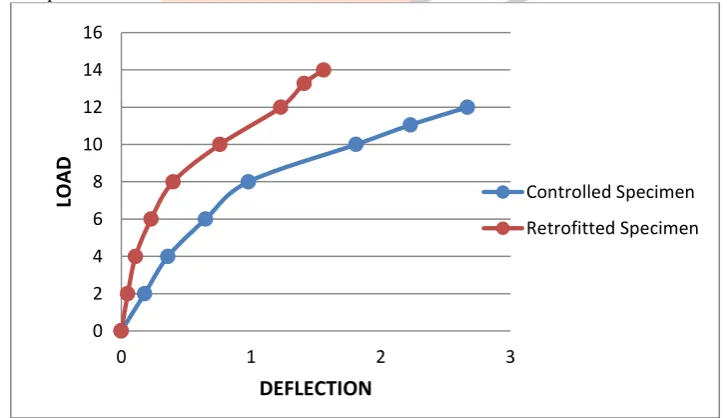
This section presents the data showing effect of retrofitting on beam column joint. Specimens which was stressed to ultimate load yielded at 20kN with ultimate failure load of 22.11kN reached at deflection of 20.43mm. But same specimen when tested after retrofitting had yielded at a load of 24kN with the ultimate failure load of 26.57kN reached at deflection of 17.89mm indicating 20 % increase for yield load and 20.2% increase in ultimate load as shown by figure-1. Also it exhibits more capacity to sustain loads after retrofitting.
Figure – 1 Load-Deflection Curve for Controlled Figure -2 Load-Deflection Curve for
and retrofitted specimen no.1 (100%Damage). Controlled and retrofitted specimen no.3 (75%Damage).
4.1.2 Effect on Joints Damaged to 75 percent stress level
Controlled specimens were stressed to only 75% of ultimate load and then tested again after retrofitting. Comparison of results of controlled and retrofitted specimens stressed to 75% stress levels after testing is presented in figure-2.Controlled specimen no 3 was stressed to 75% of ultimate load which showed a deflection of 6.47mm. A comparatively greater load at lesser deflection was observed when sample was tested after retrofitting. At the load of 19.9kN, retrofitted specimen show a deflection of 3.82mm proving to be stiffer in comparison to controlled specimen. Also the load sustained at 75% damage by retrofitted specimen was more as that of controlled specimen.
Figure-3 Load-Deflection Curve for Controlled and retrofitted specimen no.3 (50%Damage). 4.1.3 Effect on Joints Damaged to 50 percent stress level
As our study aims to observe the load deflection variation among controlled and retrofitted specimens at ultimate load, 75% damage and 50% damage. Average values of specimens which are subjected to 50% damage are discussed here. Then load and deflection after retrofitting were observed and compared to those for controlled specimens. For controlled specimens, at the load of 11.05KN the deflection was observed to be 2.24mm. After retrofitting, a clear increase in load resisting capacity can be seen through figure-3. Data indicates 20.18% increase in load resisting capacity of retrofitted specimens in comparison to controlled specimens when stressed to 50% of ultimate load.
0 5 10 15 20 25 30
0 10 20 30
LOA D DEFLECTION Controlled specimen Retrofitted Specimen 0 5 10 15 20 25
0 5 10
LOAD
DEFLECTION
Controlled Specimen Retrofitted Specimen 0 2 4 6 8 10 12 14 160 1 2 3
LOAD
DEFLECTION
Controlled Specimen
IJEDR1501078
International Journal of Engineering Development and Research (www.ijedr.org)433
V.CONCLUSIONS
The objective of study is to evaluate the effect of varying level of stresses on retrofitted beam column joint by using the technique of ferrocement jacketing. Important results obtained from study are as mentioned below:
1. For specimens subjected to 100% damage, 20% increase in yield load and 20.2% increase in ultimate load is observed. 2. For specimens subjected to 75% damage, load carrying capacity of specimen is increased by 20.3%.
3. For specimens subjected to 50% of stress levels, 20.18% increase in load carrying capacity is observed for retrofitted specimens.
REFERENCES
[1] Al-Farabi, M.S.; Baluch, M.H.; Al-Sulaimani, G.J.; and Basunbul, I.A., ―Repair of Damaged R/C Beams using Externally Bonded Fiber Glass Plates,‖ Fourth International Conference Structural Failure, Durability and Retroffiting, Singapore, July 14-16, pp. 621-628, 1993.
[2] Al. Sulyfani B.J, Mahmood M.N, Abdullah S.M, Influence of Number of Wire Mesh Layers on the Behaviour Strengthened Reinforced Concrete Columns‖, Al Rafdain Engineering, Vol.21, No.5, Oct 2013.
[3] Basunbul, I.A., Husain, M., Sharif, A.M., Al-Sulaimani, G.J., and Baluch, M.H.,―Repair of Shear Cracked R/C Beams with Bonded External Steel Plates‖. Fourth International Conference on Structural, Failure, Durability and Retro- fitting, Singapore, pp. 629-634 (1993).
[4] Ladi YV , Mohite PM ,―Experimental Evaluation of Reinforced Concrete Beam Retrofitted with Ferrocement‖, Vol- 2, No.3 , Aug2013, IISN 2319-6009.
[5] Lakshmanan.K, ISET Journal of Earthquake Technology, Paper No. 469, Vol.43, No. 1-2, March-June 2006, pp. 31- 48 [6] Lee, Jung-Yoon, Kim, Jin-Young, Oh, Gi-Jong, ―Strength deterioration of reinforced concrete beam-column joints
subjected to cyclic loading‖. Engineering Structures 31 (2009) 2070-2085.
[7] Le-Trung, Kien, Lee Kihak, Lee Jaehong, Lee Do Hyung, Woo, Sungwoo.―Experimental study of RC beam–column joints strengthened using CFRP composites.‖ Composites Part B, (2009).