Article
Computational
and
experimental
analysis
of
reinforced aerated concrete beam concrete containing
rice husk ash
Muhammad Tahir Lakhiara,*, Ather Ali b, Kong Sih Yinga, Muhammad Tarique Lakhiarc aSchool of Engineering, Monash University Malaysia
b School of Civil and Environmental Engineering, National University of Science and Technology, Pakistan c Faculty of Civil and Built Environment, Universiti Tun Hussein Onn Malaysia
* Correspondence: muhammad.lakhiar”monash.edu;
Abstract: Aerated concrete, which is manufactured from binding material, sand, foaming agent and water, is currently being utilized in the construction industry because of its lightweight and durability. The binding material, cement, along with other materials used in the concrete produces huge carbon footprints during its fabrication. The utilization of natural aggregates name as coarse aggregates depletes the natural resources of the country. Therefore, huge amounts of agricultural wastes have led scholars to investigate the effectiveness of replacing conventional materials used in concrete with agricultural wastes. In the current study, rice husk ash (RHA) was used as supplementary cementing material, thereby reducing the amount of cement used in aerated concrete (AC) mixture will reduce carbon footprints. The experimental and numerical analysis were conducted to investigate structural behavior of reinforced RAC- B beams subjected to flexural load. Parametric study on structural performance of RAC- B beam under flexure were conducted using finite element analysis (FEA). From the experiment and FEA. Results from the parametric study showed that 10%RHA-B with higher depth structurally performed better compared to RAC-B under flexure with greater load carrying capacity, lesser maximum deflection, and less cracks developing in the tension area.
Keywords: Aerated concrete, ultimate load, finite element analysis and rice husk ash.
1. Introduction
At present, construction industry mostly utilizes concrete to manufacture structural members. Concrete serves great application purposes in construction industry such as, construction of
skyscrapers, bridges, water reservoirs, highways and buildings [1-3]. The rapid development of construction industry raises the demand for concrete due to its high strength, durability, on-site
molding ability, and better economy in comparison with other building materials [4-5].
Researchers have investigated various kinds of concrete in the past such as, self-compacting
concrete, conventional concrete and foamed or aerated concrete. Aerated concrete has a dry density of 300 to 1800 kg/m3, which is 85% lighter than the conventional concrete and falls under the category
of Lightweight concrete [6-7]. To reduce the density of concrete, air-voids are introduced by utilizing a foaming agent during concrete manufacture [8]. Aerated concrete is primarily used in the construction of non-structural elements to reduce structural loads [9]. Aerated concrete is
manufactured from binding material, foaming agent and sand. Binding material such as cement is greatly used in all kinds of concrete to bind all other constituent materials together to give high
strength and hardness. Besides that, the manufacturing of cement creates huge number of environmental problems [10-11]. Cement industry is the source for the release of 10% of the total
global carbon dioxide (CO2) emissions. CO2 emissions are highly detrimental for the ozone layer and
leads to global warming and climate changes [12-13]. To over this problem great number of researchers are working to introduce the new innovative binding material.
Meanwhile, agricultural solid waste created from residential area, commercial business and institutions is increasing daily. Nowadays 1.3 billion tons per annum global municipal solid waste is
produced due to rise in population and enhancement in standard of living, approximately 1.2 kg/capita/day municipal waste is produced, but it increases to 1.42 kg/capita/day in 2020 [14]. One of the attractive solutions to overcome this issue is to recycle the agricultural waste and utilize it as
binding material or admixtures to enhance the mechanical properties of concrete. Rice husk ash, Sugar cane bagasse ash, egg shell ash and banana skin powder could be used as partial replacement
of cementing material [15].
Experimental analysis of structural member is time, energy and material consuming due to
that in this research, reinforced aerated concrete beam model containing RHA was analysed by FEA software package name as ABAQUS explicit under flexural load because it requires less disk space
and memory than Abaqus/Standard for the same simulation. For problems in which the computational cost of the two programs may be comparable, the substantial disk space and memory savings of Abaqus/Explicit make it attractive. Subsequent parametric study by changing shear span
over depth ratio was conducted and the outcomes from FEA were validated with the experimental and literature studies.
2. Materials and Methods
The experimental analysis of RAC beam contains the following steps:
Specify the beam dimensions, fabrication, and casting, curing and testing under four-point loading
condition.
2.1 RAC-B specifications
The aim of this study is to investigate the structural performance of RAC-B interms of load deflection,
ultimate load and cracking pattern. RAC-B was casted by using 0% and 10% RHA as cement replacement.
RAC-B having 1600 mm total length and rectangular cross sectional width of 100 mm and a
depth of 200 mm were used in this research.
Formwork for RAC- B was prepared by using 10 mm thick plywood sheet. The fine aggregate
(sand) was properly dried to avoid any influence on water binder ratio. The RHA used in this study was sieved from 45 micron meter because according to ASTM --- 90% cement must be sieved from 45
Figure 1. Main reinforcement and stirrups cut into design length
2.2 Testing of RAC-RHA-B
The entire test protocol for the RAC-RHA-B beams can be characterized as follows: • Instrumentation
• Procedure • Measurement. 2.2.1 Instrumentation
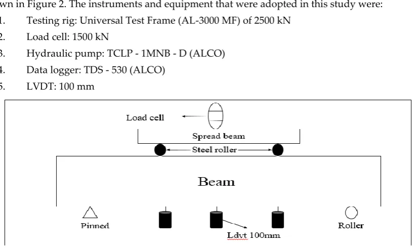
Beams were instrumented to sufficiently record their response behavior under flexural loads as shown in Figure 2. The instruments and equipment that were adopted in this study were:
1. Testing rig: Universal Test Frame (AL-3000 MF) of 2500 kN 2. Load cell: 1500 kN
3. Hydraulic pump: TCLP - 1MNB - D (ALCO)
4. Data logger: TDS - 530 (ALCO) 5. LVDT: 100 mm
Figure 2. Flexural test setup for beam
2.2.2 Procedure
After the installation of instruments, load was constantly applied at the mid-section of the beam and transferred load to beam by load spreader by using manually controlled hydraulic jack with a loading rate of 5 kN/min. The flexural load during the beam testing was recorded by the load cell. A data
logger was combined to the load cell to record the applied loading and the corresponding deflections until the beam reached the ultimate failure strength.
2.2.3 Measurement
Deflection of the beam was noted by using three linear variable differential transducer (LVDTs) with
a gauge length of 120 mm. LVDTs were installed at three different locations, namely, at the mid-span
and under the point loading of beam. The base of LVDTs were linked to the steel hooks which were
placed at the vertical portion of the beam as the load applied the beam deflect so deflection were
recorded as shown in Figure 2 . The LVDTs were joint to the data logger to get the deflection data.
In this way, the attached data logger was developed initial readings for deflection. The results for
deflection of the beam at each incremental load were recorded continuously during the test.
3. Finite element analysis of RAC-RHA-B
The three dimensional-nonlinear finite element beam models were modelled by FEA computer based
3.1 Element kinds of each materials
RAC-B and RAC-10%RHA-B were analysed separately, the part of Abaqus module by adopting different kinds of element based on the suitability of each element. The element used for each part
are arranged in Table 1 and Table 2, the element type selected for each part are created on the appropriateness and competence of the element type. The modelling procedure for RAC-RHA-B
including discretized geometry, element section properties, material data, loading and boundary conditions, analysis types and output are described in next sections.
Table 1. Element used for each part of PSCC beam
No. Part Element Definition of Element
1 Aerated concrete C3D8R
Continuum three dimensional 8 nodes linear brick element, reduced integration and hourglass control
2 Main reinforcement T3D2 Three dimensional 2 nodes truss element
3 Stirrups T3D2 Three dimensional 2 nodes truss element
The RAC-RHA-B model was initially established with geometric discretization of each part. The steel reinforcement was simulated using three dimensional 2-node elements. The concrete
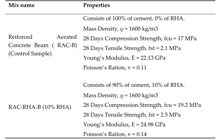
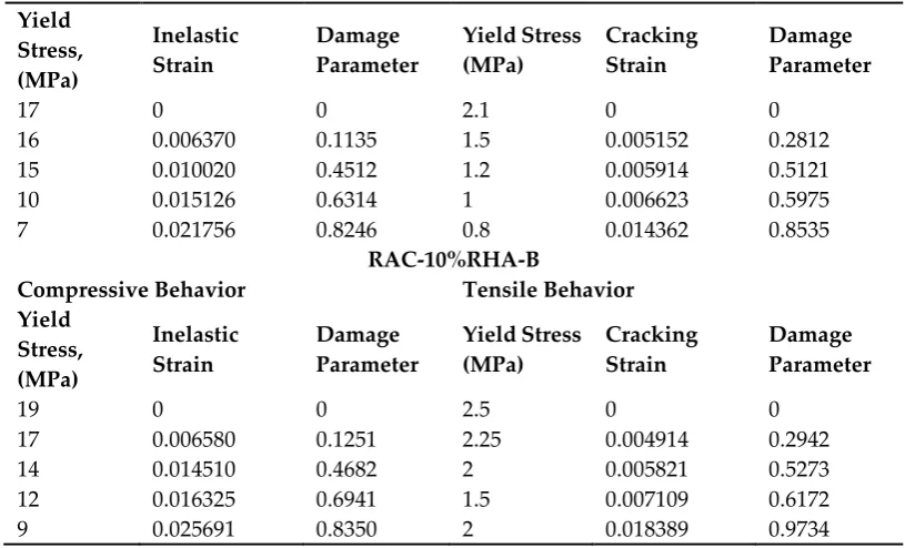
damage plasticity of RAC-B and RAC-10%RHA-B which were extracted from the experimental outcomes are presented in Table 3. The dilatation angle, eccentricity, initial biaxial/ uniaxial ratio,
viscosity were taken from Rahman et al. (2019) [16].
Table 2. The materials properties of RAC-RHA-B
Mix name Properties
Reiforced Aerated Concrete Beam ( RAC-B) (Control Sample)
Consists of 100% of cement, 0% of RHA.
Mass Density, ρ = 1600 kg/m3
28 Days Compression Strength, fcu = 17 MPa
28 Days Tensile Strength, fst = 2.1 MPa
Young’s Modulus, E = 22.13 GPa
Poisson’s Ration, v = 0.11
RAC-RHA-B (10% RHA)
Consists of 90% of cement, 10% of RHA.
Mass Density, ρ = 1600 kg/m3
28 Days Compression Strength, fcu = 19.2 MPa
28 Days Tensile Strength, fst = 2.5 MPa
Young’s Modulus, E = 24.98 GPa
Poisson’s Ration, v = 0.14
Table 3. Concrete damaged plasticity of aerated concrete Concrete Damaged Plasticity
Dilatation
Angle Eccentricity
Initial biaxial/ uniaxial
ratio, σc0/σb0 K Viscosity
32° 1 1.13 0.6 0
RAC- B
Yield Stress, (MPa) Inelastic Strain Damage Parameter Yield Stress (MPa) Cracking Strain Damage Parameter
17 0 0 2.1 0 0
16 0.006370 0.1135 1.5 0.005152 0.2812
15 0.010020 0.4512 1.2 0.005914 0.5121
10 0.015126 0.6314 1 0.006623 0.5975
7 0.021756 0.8246 0.8 0.014362 0.8535
RAC-10%RHA-B
Compressive Behavior Tensile Behavior
Yield Stress, (MPa) Inelastic Strain Damage Parameter Yield Stress (MPa) Cracking Strain Damage Parameter
19 0 0 2.5 0 0
17 0.006580 0.1251 2.25 0.004914 0.2942
14 0.014510 0.4682 2 0.005821 0.5273
12 0.016325 0.6941 1.5 0.007109 0.6172
9 0.025691 0.8350 2 0.018389 0.9734
3.2 Convergence study
The quasi-static analysis method was further method with different element extents as shown in Tables 4 to demonstrate mesh sensitivity. Similar material characteristics were used for all mesh sizes.
Results of the FEA analysis using different mesh density for RAC-B (control sample) are presented in Table 5. Figure 2 demonstrates the effects of mesh sizes on the results of the analysis. The result
converged to a near constant value when the number of element reached 15,234. Load versus vertical displacement presented similar behaviour for model with global size 17, 15 and 13 thus the suitable
mesh density chosen for parametric study was global size 17 to 13 or about 15,234 to 23,143 elements. The difference in element number was due to size difference of RAC-RHA-B.
Table 4. Result of mesh enhancement study of RAC-RHA-B (Control beam)
Mesh Size
Total Elements
Pu (kN) FEA
Pu (kN)
Experiment
% of
Difference
GB200 24 71.12 42 69.33%
GB150 28 68.19 42 62.35%
GB100 108 62.53 42 47.61%
GB50 612 59.32 42 41.23%
GB30 2,650 55.76 42 12.69%
GB25 4,608 50.12 42 32.76%
GB20 9,360 48.75 42 16.07%
GB17 15,235 44.71 42 6.45%
GB15 18,619 44.71 42 6.45%
GB13 23,143 44.71 42 6.45%
Figure 2. Result of mesh enhancement study of RAC-RHA-B (Control beam) 3.3 Boundary conditions
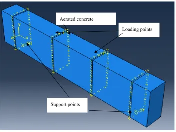
The point load was applied at the top surface of the beams and simply supported boundary conditions were provided at the bottom surface of the beam. After the RAC-RHA-B model was
assembled, the discrete modelled section was connected appropriately to each other. Embedded approach was implemented to make appropriate interaction between aerated concrete and steel
reinforcement as presented in Figure 3.
Figure 3. Structural model of PSCC beam
For point line load, displacement was assigned at Y direction at the reference point on the
rigid body to simulate the applied loading on the top of the beam.
From the given vertical displacement, the equivalent loading given on RAC-RHA-B could be found from the history output in the outcome result file. Vertical displacement was rise
significantly as the applied force magnitude increases until the beam failed at ultimate load and post failure occurred.
0 10 20 30 40 50 60 70 80
24 28 108 612 2,650 4,608 9,360 15,235 18,619 23,143
Pu FEA
(
kN)
Total Elements
Loading points Aerated concrete
Finally, the convergence of RAC-RHA-B was observed with mesh sensitivity analysis by changing
the mesh density to get the final mesh size for RAC-RHA-B. The critical outcomes parameters from the FEA were validated with the experimental results.
4. Results and discussions
The outcomes such as ultimate load, cracking pattern and load deflection profile of RAC-RHA-B from
ABAQUS simulation were extracted from post processing and validated with the experimental
results.
4.1 Ultimate load
The ultimate load, maximum load carried by the beam before failure, obtained from experiment and
FEA are shown in Table 5. The results presented in Table 5 show that RAC-10%RHA-B from
experiments and FEA give approximately 18.5% higher ultimate load than the control sample. In
general, FEA outcomes presented higher ultimate load compared to experimental results. This is due
to the fact that FEA works under ideal conditions whereas experimental investigations are prone to
a variety of external influences. The percentage variation of the ultimate load outcomes from
experiments and FEA for all beam samples were documented in the range of 5.88% to 7.5%. This
difference is satisfactory because it is less than 20% for analysing the structural behaviour of the beam
subjected to flexural load. Wang et al., (2018) [17]; Sjaarda et al., (2018)[18] and Murthy et al., (2018)
[19], analysed the structural behaviour of reinforced concrete beam by experimental work and FEA.
The outcomes demonstrated that the difference between experimental and FEA outcomes were 10%
to 15%.
Table 5. Ultimate load carrying capacity of PSCC beam
Beam
Ultimate Load (kN)
𝑷𝒖(𝑭𝑬𝑨)− 𝑷𝒖(𝑬𝑿𝑷) 𝑷𝒖(𝑬𝑿𝑷)
𝒙 𝟏𝟎𝟎% Experiment FEA
RAC-B (Control sample) 34 36 5.88%
RAC-10%RHA-B 40 43 7.5%
4.2 Cracking profile of RAC-RHA-B
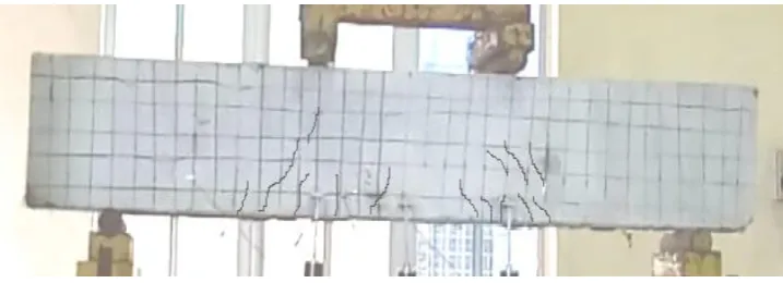
The cracking pattern of all RAC-RHA beams from FEA are shown in Figure 4. The failure mode and
cracking profile were validated with the experimental outcomes and the previous studies conducted
by Vilke et al., (2017) [20]; Wahalathantri et al., (2011) [21] and Sihau et al., (2015) [22], which analysed
the cracking pattern of simply supported reinforced concrete beam under point load using Abaqus.
The results showed that first crack appeared at the bottom of the beam close to the centre of the span.
The cracks appeared at the tension zone and moved towards the compression zone as load increased.
The outcomes of cracking pattern of RAC-RHA beams from FEA were found to have similar trends
(a)
Crack pattern of RAC-B by Experimental(b)Crack pattern of RAC-B by FEA
(c)Crack pattern of RAC-10%RHA-B by Experimental
(d)Crack pattern of RAC-10%RHA-B by FEA
4.3 Validation of load versus deflection
Table 6 shows the maximum deflection of all RAC-RHA beams as documented from experiments
and FEA. B (control beam) recorded highest maximum deflection value while
RAC-10%RHA-B recorded the least deflection value, in both experiments and FEA. From Table 6, it is
seen that the maximum deflection obtained from FEA was slightly lesser then the maximum
deflection obtained from the experimental results. The percentage difference between FEA and
experimental results of maximum deflection are in the range of 5% to 7.5%. This is in good
agreement with the results obtained from previous researches conducted by Charan & Topdar
(2015)[23]; Vilke et al., (2017) [20] and Mendis et al., (2018)[24]. In these studies, the RCC beams
containing fibres were analysed by experiment and FEA. The results demonstrated that the
deflection obtained from the FEA were 5% to 15 % less than the experimental analysis.
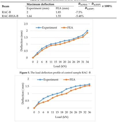
Load-deflection graphs of RAC -B and RAC-10%RHA-B beams are presented in Figure 5,
and Figure 6, respectively. These graphs show similar load-deflection profiles from experiments
and FEA.
Table 6. Maximum deflection of RAC-RHA beam
Beam Maximum deflection 𝑫𝒖(𝑭𝑬𝑨)𝑫 − 𝑫𝒖(𝑬𝑿𝑷)
𝒖(𝑬𝑿𝑷)
𝒙 𝟏𝟎𝟎% Experiment (mm) FEA (mm)
RAC-B 2 1.85 -7.5%
RAC-RHA-B 1.64 1.55 -5.48%
Figure 5. The load deflection profile of control sample RAC- B
Figure 6: The load deflection profile of RAC- 10% RHA-B 0 0.5 1 1.5 2 2.5
0 2 6 8 11 15 18 20 24 26 29 31 34
Def lec ti o n ( m m ) Load (kN) Experiment FEA 0 0.5 1 1.5 2
0 3 6 8 11 15 18 20 24 26 29 32 36
5. Parametric Study:
The parametric study was conducted to investigate the effect of beam height on failure modes and load deflection profiles of RAC-10%RHA-B. As the height of the beam greatly influences its structural
performance, therefore, it is pertinent to investigate its influence on failure modes and crack patterns. For this purpose, three different beams of depth 300mm, 400mm and 500mm were investigated.
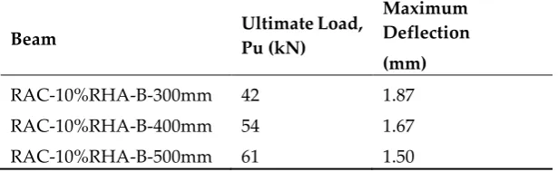
The impact of different heights on ultimate load, load-deflection pattern and crack profile were analysed. Table 7 demonstrates the structural behaviour of beams with various heights in terms of ultimate load and maximum deflection while all other factors such as, the overall length, width
and material characteristics of beam were kept constant.
The results in Table 7 show that the height of beam greatly influences beam strength, and the
ultimate strength (Pu), was increased with the increment of beam height. While the maximum deflection decreased with the increment of height. Thus, suggesting direct relation between the
height and strength, but inverse relation between height and ductility.
The load-deflection profile of RAC-10%RHA-B having different depths are shown in Figure
7. It can be seen from the figure that maximum deflection was recorded for beam with 300 mm height. It performed in the most ductile manner compared to the other beams. Whereas, the lowest deflection was recorded for beam with 500 mm height. This beam had the most brittle behaviour out
of all beam sizes.
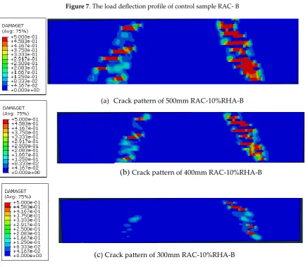
The cracking pattern is shown in Figure8. The 400mm and 500mm depth beams were
observed to exhibit flexural shear failure mode. Both beams experienced inclined crack at about 30° from horizontal, appeared from bottom part of the left zone of beam. The crack then initiated to
propagate in diagonal direction as it moves towards the upper end of the beam along with the continuation to propagate in length and widen in width. Where as, 300mm beam exhibited flexure
failure mode where it experienced discontinued straight-line cracks which propagated from the bottom part of beam.
The findings obtained from Abaqus have good agreement with the outcomes found in the
previous researches by Metwally et al., (2017) [25] and Jawarkar & Kadam (2017) [26], which analysed the structural performance of deep beams means of FEA. The outcomes demonstrated that as depth
of beam increases ultimate load of reinforced beams increases whereas the deflection of beam decreases.
Table 7. Effects of various depth of beam on ultimate strength and maximum deflection of PSCC-beam
Beam Ultimate Load, Pu (kN)
Maximum Deflection (mm)
RAC-10%RHA-B-300mm 42 1.87
RAC-10%RHA-B-400mm 54 1.67
Figure 7. The load deflection profile of control sample RAC- B
Figure 8. Cracking pattern of RAC-10%RHA-B with different depths 6. Conclusion
Utilization of rice husk ash (RHA) as supplementary cementing material was help to enhance the strength and also contribute to protect the environment from agricultural waste. In this research,
RAC-10%RAC-B model possessed the higher ultimate load and lower deflection values at has higher 0
0.2 0.4 0.6 0.8 1 1.2 1.4 1.6 1.8 2
0 2 6 8 11 15 18 20 24 26 29 31 34 42 48 54 58 61
Def
lec
ti
o
n
(
m
m
)
Load (kN) RAC-10%RHA-B 300mm
RAC-10%RHA-B 400mm
RAC-10%RHA-B 500mm
(a) Crack pattern of 500mm RAC-10%RHA-B
(b) Crack pattern of 400mm RAC-10%RHA-B
values at 40 kN and 1.64 mm as compared to control sample (RAC-B) beam at 34 kN mm 2 mm
respectively. The FEA results were validated with Laboratorial outcomes. The ultimate load obtained from FEA was 8 % greater than experimental results. Parametric study with different depths
has greatly impact on the ultimate load, deflection and cracking pattern. Meanwhile, the failure mechanism were almost similar to the experimental outcomes. However, it could be demonstrated
that the Abaqus had capability to predict the structural performance of RAC-10%RHA-B. Further work on parametric study of foamed concrete is highly recommended with different boundary conditions, beam model dimension and various material properties to overcome financial and time
constraint.
Author Contributions: For this research articles four authors were contributed. The details of contributions are provided below;
Mr. Muhammad Tahir Lakhiar and Dr Ather Ali conceived of the presented idea. Mr. Muhammad Tahir Lakhiar developed the theory and performed the computations. Dr Ather Ali and Mr
Muhammad Tarique lakhiar verified the analytical methods. Dr Kong Sih Ying encouraged Mr. Muhammad Tahir Lakhiar to investigate computational analysis of aerated concrete beam and
supervised the findings of this work. All authors discussed the results and contributed to the final manuscript.
Conflicts of Interest:
All above mentioned authors declare that there is no conflict of interest.
References
1. Gyurkó, Z., Jankus, B., Fenyvesi, O., & Nemes, R. Sustainable applications for utilization the
construction waste of aerated concrete. Journal of Cleaner Production, (2019) 230, 430-444.
https://doi.org/10.1016/j.jclepro.2019.04.357
2. Memon, I. A., Jhatial, A. A., Sohu, S., Lakhiar, M. T., & Hussain, Z. Influence of fibre length on the
behaviour of polypropylene fibre reinforced cement concrete. Civil Engineering Journal, (2018) 4(9),
2124-2131. https://pdfs.semanticscholar.org/333c/638305b03d275077f74b4fe0106dbf94d53c.pdf
3. Zhang, N., Duan, H., Miller, T. R., Tam, V. W., Liu, G., & Zuo, J. Mitigation of carbon dioxide by
accelerated sequestration in concrete debris. Renewable and Sustainable Energy Reviews, (2020), 117,
109495. https://doi.org/10.1016/j.rser.2019.109495
4. Han, F., Luo, A., Liu, J., & Zhang, Z. Properties of high-volume iron tailing powder concrete under
different curing conditions. Construction and Building Materials, (2020)., 241, 118108.
https://doi.org/10.1016/j.conbuildmat.2020.118108
5. He, X., Zheng, Z., Ma, M., Su, Y., Yang, J., Tan, H., ... & Strnadel, B. New treatment technology: The use
of wet-milling concrete slurry waste to substitute cement. Journal of Cleaner Production, (2020), 242,
118347. https://doi.org/10.1016/j.jclepro.2019.118347
6. Jhatial, A. A., Goh, W. I., Mohamad, N., Hong, L. W., Lakhiar, M. T., Samad, A. A. A., & Abdullah, R.
The Mechanical Properties of Foamed Concrete with Polypropylene Fibres. International Journal of
Engineering & Technology, (2018), 7(3.7), 411-413.
7. Keerio, M. A., Lakhiar, M. T., & Sohu, S. Comparative Study on Flexural Performance of Foamed
Concrete Beam Containing Plastic Fibres. International Journal of Sustainable Construction Engineering and
Technology, (2019) 10(1), pp. 10-18.
a. https://publisher.uthm.edu.my/ojs/index.php/IJSCET/article/view/3569
8. Kamaruddin, S., Goh, W. I., Jhatial, A. A., & Lakhiar, M. T. Chemical and Fresh State Properties of
Foamed Concrete Incorporating Palm Oil Fuel Ash and Eggshell Ash as Cement
Replacement. International Journal of Engineering & Technology, (2018), 7(4.30), 350-354.
https://www.researchgate.net/profile/Ashfaque_Jhatial/publication/329450930
9. Habib, A., Begum, H. A., & Hafiza, E. R. Study on production of Aerated concrete block in
Bangladesh. International Journal of Innovative Science, Engineering and Technology, (2015),2, 200-203.
a. https://www.researchgate.net/profile/Ahsan_Habib14/publication/274639775
10. He, X., Zheng, Z., Yang, J., Su, Y., Wang, T., & Strnadel, B. Feasibility of incorporating autoclaved
aerated concrete waste for cement replacement in sustainable building materials. Journal of Cleaner
Production, (2020). 250, 119455. https://doi.org/10.1016/j.jclepro.2019.119455
11. Raj, A., Borsaikia, A. C., & Dixit, U. S. Manufacturing of Autoclaved Aerated Concrete (AAC): Present
Status and Future Trends. In Advances in Simulation, Product Design and Development, (2020) (pp.
825-833). Springer, Singapore. https://doi.org/10.1016/j.conbuildmat.2019.117721
12. Mohamad, N., Lakhiar, M. T., Samad, A. A. A., Mydin, M. A. O., Jhatial, A. A., Sofia, S. A., ... & Ali, N.
Innovative and sustainable green concrete–A potential review on utilization of agricultural waste.
In IOP Conference Series: Materials Science and Engineering(2019, August), (Vol. 601, No. 1, p. 012026).
IOP Publishing. https://iopscience.iop.org/article/10.1088/1757-899X/601/1/012026/meta
13. Mohamad, N., Samad, A. A. A., Lakhiar, M. T., Mydin, M. A. O., Jusoh, S., Sofia, A., & Efendi, S. A.
Effects of Incorporating Banana Skin Powder (BSP) and Palm Oil Fuel Ash (POFA) on mechanical
properties of lightweight foamed concrete. International Journal of Integrated Engineering, (2018), 10(9),
pp 101-109. .https://publisher.uthm.edu.my/ojs/index.php/ijie/article/view/3104
14. Vishwakarma, V., & Uthaman, S. Environmental impact of sustainable green concrete. In Smart
Nanoconcretes and Cement-Based Materials, (2020). (pp. 241-255). Elsevier.
https://doi.org/10.1016/B978-0-12-817854-6.00009-X
15. Das, S. K., Singh, S. K., Mishra, J., & Mustakim, S. M. Effect of Rice Husk Ash and Silica Fume as
Strength-Enhancing Materials on Properties of Modern Concrete—A Comprehensive Review.
In Emerging Trends in Civil Engineering, (2020), (pp.253-266). Springer, Singapore.
https://link.springer.com/chapter/10.1007/978-981-15-1404-3_21.
16. Rahman, A. F., Goh, W. I., Mohamad, N., Kamarudin, M. S., & Jhatial, A. A. Numerical analysis and
experimental validation of reinforced foamed concrete beam containing partial cement
replacement. Case Studies in Construction Materials, (2019), 11, e00297.
17. Wang, Z., Yang, Z., Yang, Y., & Xian, G. Flexural fatigue behavior of a pultruded basalt fiber reinforced
epoxy plate subjected to elevated temperatures exposure, Polymer Composites, (2018), 39(5), pp.
18. Sjaarda, M., Walbridge, S., & West, J. S. Assessment of Shear Connection through Composite Beam
Modeling. Transportation Research Record,(2018), 3, pp. 1-9.
19. Murthy, A. R., Karihaloo, B. L., Rani, P. V., & Priya, D. S. Fatigue behaviour of damaged RC beams
strengthened with ultra-high-performance fibre reinforced concrete. International Journal of
Fatigue,(2018) 116, pp. 659-668.
20. Vilke, T. G. Structural performance of a prefabricated concrete beam with longitudinal cavities.
University of Stavanger, (2017) Norway: Master's Thesis.
21. Wahalathantri, B. L., Thambiratnam, D. P., Chan, T. H. T. & Fawzia, S. A material model for flexural
crack simulation in reinforced concrete elements using ABAQUS. Proceedings of the first international
conference on engineering, designing and developing the built environment for sustainable wellbeing. Queensland
University of Technology: QUT e prints. (2011), pp. 260-264.
22. Sihua, D., Ze, Q. & Li, W. Nonlinear Analysis of Reinforced Concrete Beam Bending Failure
Experimentation Based on ABAQUS. Analysis, (2015). 73, pp. 10-16.
23. Charan, B. & Topdar, P., On Finite Element Analysis of Steel and RC Beams: Performance of Different
Elements, Journal of Mechanical and Civil Engineering, (2015), 2, pp. 13-18.
24. Mendis, A. S., Al-Deen, S., & Ashraf, M. Flexural shear behaviour of reinforced Crumbed Rubber
Concrete beam. Construction and Building Materials, (2018), 166, pp. 779-791.
25. Metwally, I. M. Three-dimensional nonlinear finite element analysis of concrete deep beam reinforced
with GFRP bars. HBRC journal, (2017), 13(1), pp. 25-38.
26.
Jawarkar, V. S., & Kadam, K. N., Finite Element Analysis of Reinforced Concrete Deep Beams with
Large Openings. International Journal of Innovative Research in Science, Engineering and Technology,(2017),