IJEDR1402038
International Journal of Engineering Development and Research (www.ijedr.org)1522
Efficient Majority Logic Fault Detector/Corrector
Using Euclidean Geometry Low Density Parity
Check (EG-LDPC) Codes
1
U.Rahila Begum,
2V. Padmajothi
1PG Student, 2Assistant Professor 1
Department Of VLSI Design, SRM University, Kattangulathur, Tamilnadu, India 2Department of ECE, SRM University, Kattangulathur, India
________________________________________________________________________________________________________
Abstract - Error detection in memory applications was proposed to accelerate the majority logic decoding of difference set low density parity check codes. This is useful as majority logic decoding can be implemented serially with simple hardware but requires a large decoding time. For memory applications, this increases the memory access time. The method detects whether a word has errors in the first iterations of majority logic decoding, and when there are no errors the decoding ends without completing the rest of the iterations. Since most words in a memory will be error free, the average decoding time is greatly reduced. In this brief, the application of a similar technique to a class of Euclidean geometry low density parity check (EG-LDPC) codes that are one step majority logic decodable. The results obtained show that the method is also effective for EG-LDPC codes. Extensive simulation results are given to accurately estimate the probability of error detection for different code sizes and numbers of errors.
________________________________________________________________________________________________________
I. INTRODUCTION
Error correction codes are commonly used to protect memories from so-called soft errors, which change the logical value of memory cells without damaging the circuit. As technology scales, memory devices become larger and more powerful error correction codes are needed. To this end, the use of more advanced codes has been recently proposed. These codes can correct a larger number of errors, but generally require complex decoders. To avoid a high decoding complexity, the use of one step majority logic decodable codes was first proposed in for memory applications. Further work on this topic was then presented in this paper. One step majority logic decoding can be implemented serially with very simple circuitry, but requires long decoding times. In a memory, this would increase the access time which is an important system parameter. Only a few classes of codes can be decoded using one step majority logic decoding. Among those are some Euclidean geometry low density parity check (EG-LDPC) codes which were used in, and difference set low density parity check (DS-(EG-LDPC) codes.
A method was recently proposed in to accelerate a serial implementation of majority logic decoding of DS-LDPC codes. The idea behind the method is to use the first iterations of majority logic decoding to detect if the word being decoded contains errors. If there are no errors, then decoding can be stopped without completing the remaining iterations, therefore greatly reducing the decoding time.
II. PROPOSEDSYSTEM
A. Introduction
In error detection and correction, majority logic decoding is a method to decode repetition codes, based on the assumption that the largest number of occurrences of a symbol was the transmitted symbol. MLD is based on a number of parity check equations which are orthogonal to each there. So that, at each iteration, each code word bit only participates in one parity check equation, except the very first bit which contributes to all equations. For this reason, the majority result of these parity check equations decide the correctness of the current bit under decoding.
Block Diagram of MLD
Fig.1. Memory System Schematic With MLD
IJEDR1402038
International Journal of Engineering Development and Research (www.ijedr.org)1523
suffered while being stored in the memory.B. A Plain ML Decoder
There are two ways for implementing this type of decoder. The first one is called the Type-I ML decoder, which determines, upon XOR combinations of the syndrome, which bits need to be corrected. The second one is the Type-II ML decoder that calculates directly out of the code word bits the information of correctness of the current bit under decoding. Both are quite similar but when it comes to implementation, the Type-II uses less area, as it does not calculate the syndrome as an intermediate step.
As described before, the ML decoder is a simple and powerful decoder, capable of correcting multiple random bit-flips depending on the number of parity check equations. It consists of four parts as illustrated in Fig.3.2. The input signal is initially stored into the cyclic shift register and shifted through all the taps. The intermediate values in each tap are then used to calculate the results of the check sum equations from the XOR matrix. In the cycle, the result has reached the final tap, producing the output signal (which is the decoded version of input).
As stated before, input might correspond to wrong data corrupted by a soft error. To handle this situation, the decoder would behave as follows. After the initial step, in which the code word is loaded into the cyclic shift register, the decoding starts by calculating the parity check equations hardwired in the XOR matrix. The resulting sums are then forwarded to the majority gate for evaluating its correctness. If the number of 1’s received in is greater than the number of 0’s that would mean that the current bit under decoding is wrong and a signal to correct it would be triggered. Otherwise, the bit under decoding would be correct and no extra operations would be needed on it.
In order to improve the decoder performance, alternative designs may be used. One possibility is to add a fault detector by calculating the syndrome, so that only faulty code words are decoded. Since most of the code words will be error-free, no further correction will be needed, and therefore performance will not be affected. Although the implementation of an SFD reduces the average latency of the decoding process, it also adds complexity to the design.
C. Majority Logic Decoder/Detector/corrector
The results for the exhaustive checks are shown in Table II. These results prove the hypothesis for the codes with smaller word size (N=15 and N=63). For N=255 up to three errors have been exhaustively tested while for N=1023 only single and double error combinations have been exhaustively tested.
To complement the results of the exhaustive checks for larger codes and number of errors, simulations using random error patterns have been used. In all the experiments, one billion error combinations are tested. The results for errors affecting more than four bits are shown in Table III, since for errors affecting up to four bits there were no undetected errors. It can be observed that for errors affecting more than four bits there is a small number of error combinations that will not be detected in the first three iterations. This number decreases with word size and also with the number of errors. The decrease with the word size can be explained as follows, the larger the word size, the larger the number of MLD check equations in Table I and therefore it is more unlikely that errors occur in the same equation. As for the number of errors, a similar reasoning applies: the more errors occur, the larger the probability that an odd number of errors occurs in at least one equation. Finally it must be noted that the probabilities of undetected errors are different for an even and an odd number of errors as in the latter case, one of the errors must occur in a bit which is not checked by any equation.
The simulation results presented suggest that all errors affecting three and four bits would be detected in the first three iterations. For errors affecting a larger number of bits, there is a small probability of not being detected in those iterations. For large word sizes, the probabilities are sufficiently small to be acceptable in many applications.
IJEDR1402038
International Journal of Engineering Development and Research (www.ijedr.org)1524
D. Correction
One-step majority-logic correction is a fast and relatively compact error-correcting technique One-step majority logic correction is the procedure that identifies the correct value of a each bit in the code word directly from the received code word. Avoiding iteration makes the correction latency both small and deterministic. This technique can be implemented serially to provide a compact implementation or in parallel to minimize correction latency. This method consists of two parts: 1) generating a specific set of linear sums of the received vector bits and 2) finding the majority value of the computed linear sums. The majority value indicates the correctness of the code-bit under consideration; if the majority value is 1, the bit is inverted, otherwise it is kept unchanged. A linear sum of the received encoded vector bits can be formed by computing the inner product of the received vector and a row of a parity-check matrix. This sum is called Parity-Check sum.
E. Need For Error Detection
Environmental interference and physical defects in the communication medium can cause random bit errors during data transmission. Error coding is a method of detecting and correcting these errors to ensure information is transferred intact from its source to destination. The “code word" can then be decoded at the destination to retrieve the information. The extra bits in the code word provide redundancy that, according to the coding scheme used, will allow the destination to use the decoding process to determine if the communication medium introduced errors and in some cases correct them so that the data need not be retransmitted. Different error coding schemes are chosen depending on the types of errors expected, the communication medium's expected error rate, and whether or not data retransmission is possible. Faster processors and better communications technology make more complex coding schemes, with better error detecting and correcting capabilities, possible for smaller embedded systems, allowing for more robust communications. However, tradeoffs between bandwidth and coding overhead, coding complexity and allowable coding delay between transmissions, must be considered for each application.
F. Error Detecting Codes
Here we will only consider binary messages and so the transmitted messages consist of strings of 0’s and 1’s. The essential idea of forward error control coding is to augment these message bits with deliberately introduced redundancy in the form of extra check bits to produce a codeword for the message. These check bits are added in such a way that code words are sufficiently distinct from one another that the transmitted message can be correctly inferred at the receiver, even when some bits in the codeword are corrupted during transmission over the channel. The simplest possible coding scheme is the single parity check code (SPC).The SPC involves the addition of a single extra bit to the binary message, the value of which depends on the bits in the message. In an even parity code, the additional bit added to each message ensures an even number of 1s in every codeword.
One Dimensional Parity Check
The most common and least expensive mechanism for error- detection is the simple parity check. In this technique, a redundant bit called parity bit, is appended to every data unit so that the number of 1’s in the unit (including the parity becomes even). Blocks of data from the source are subjected to a check bit or Parity bit generator form, where a parity of 1 is added to the block if it contains an odd number of 1’s (ON bits) and 0 is added if it contains an even number of 1’s. At the receiving end the parity bit is computed from the received data bits and compared with the received parity bit, as shown in Fig. 3.9. This scheme makes the total number of 1’s even, that is why it is called even parity checking.
Parity Check Code
Note that for the sake of simplicity, we are discussing here the even-parity checking, where the number of 1’s should be an even number. It is also possible to use odd-parity checking, where the number of 1’s should be odd.
Two Dimensional Parity Check
Performance can be improved by using two-dimensional parity check, which organizes the block of bits in the form of a table. Parity check bits are calculated for each row, which is equivalent to a simple parity check bit. Parity check bits are also calculated for all columns then both are sent along with the data. At the receiving end these are compared with the parity bits calculated on the received data.
Two Dimensional Parity Checking increases the likelihood of detecting burst errors. As we have shown above that a 2-D Parity check of n bits can detect a burst error of n bits. A burst error of more than n bits is also detected by 2-D Parity check with a high-probability. There is, however, one pattern of error that remains elusive. If two bits in one data unit are damaged and two bits in exactly same position in another data unit are also damaged, the 2-D Parity check checker will not detect an error. For example, if two data units: 11001100 and 10101100. If first and second from last bits in each of them is changed, making the data units as 01001110 and 00101110, the error cannot be detected by 2-D Parity check.
G. Low Density Parity Check Codes
LDPC codes are block codes with parity-check matrices that contain only a very small number of non-zero entries. In which guarantees both a decoding complexity which increases only linearly with the code length and a minimum distance which also increases linearly with the code length.
IJEDR1402038
International Journal of Engineering Development and Research (www.ijedr.org)1525
matrix first and then determining a generator matrix for the code afterwards. The biggest difference between LDPC codes and classical block codes is how they are decoded. Classical block codes are generally decoded with ML like decoding algorithms and so are usually short and designed algebraically to make this task less complex. LDPC codes however are decoded iteratively using a graphical representation of their parity-check matrix.III. BLOCKDIAGRAM
IV. RESULTSANDDISCUSSIONS
A. Simulation Result of Encoder
Fig 5.1 Simulation Result of Encoder
Fig 5.1 shows the simulation result of an Encoder. The data input to given to the memory is encoded first through this encoder block. The input to the encoder is the 7 bit information and output is the 15 bit information. The signal output is form s1 to s8.
IJEDR1402038
International Journal of Engineering Development and Research (www.ijedr.org)1526
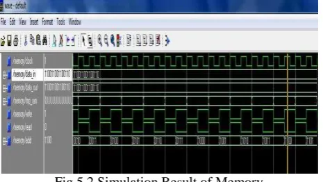
Fig 5.2 Simulation Result of MemoryFig 5.2 shows the simulation result of the memory. The data in and data out of the memory is the 15 bit information taken from the encoder. The temporary RAM is used as memory element. The clock event is used to read from the memory and write data to the memory. The memory address of the particular data is also specified.
C. Simulation Result of Majority Logic Decoder With Control
Fig 5.3 Simulation Result of MLD With Control
Fig 4.3 shows the Majority logic decoder with control. The control input is x which is the 15 bit information and the control clock given. The control output is y which is also the 15 bit information. The row density is calculated from 1 to 4. The Majority gate output is obtained by Ex-Or operation. The data output with error and without error are calculated.
D. Simulation Result of Serial Majority Logic Decoder
Fig 5.4 Simulation Result of Serial MLD
Fig 5.4 shows the output of the Serial Majority logic decoder. In this decoder the data read from the memory is given as serial input to the decoder. The data is verified whether it is with error or without error by serial cyclic shifting. This method is called One Step Majority Logic Decoding.
IJEDR1402038
International Journal of Engineering Development and Research (www.ijedr.org)1527
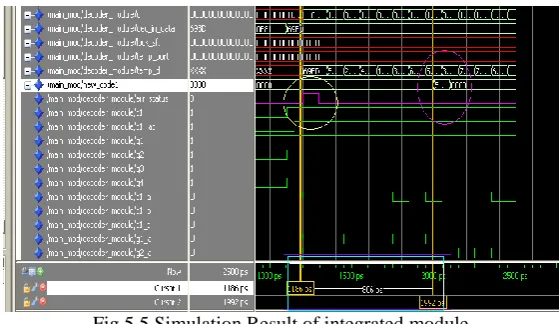
Fig 5.5 Simulation Result of integrated moduleFigure 5.5 shows that the as soon as the error is identified the data starts shifting to correct the fault and generates new code. The new code is again fetched to the memory. We can see here rising clock as the error is detected.
V. CONCLUSION
The detection of errors during the first iterations of serial one step Majority Logic Decoding of EG-LDPC codes has been studied. The objective was to reduce the decoding time by stopping the decoding process when no errors are detected. The simulation results show that all tested combinations of errors affecting up to four bits are detected in the first three iterations of decoding. These results extend the ones recently presented for DS-LDPC codes, making the modified one step majority logic decoding more attractive for memory applications. The designer now has a larger choice of word lengths and error correction capabilities.
REFERENCES
[1] Pedro Reviriego, Juan A. Maestro, and Mark F. Flanagan, (Jan 2013)“Error Detection in Majority Logic Decoding of Euclidean Geometry Low DensityParity Check (EG-LDPC) Codes,” IEEE Trans. Very Large Scale Integr.(VLSI) Syst.. vol. 21, no. 1,
[2] Liu.S, P. Reviriego, and J. Maestro, (Jan. 2012) “Efficient majority logic fault detection with difference-set codes for memory applications,” IEEETrans. Very Large Scale Integr. (VLSI) Syst., vol. 20, no. 1, pp. 148–156,.
[3] Naeimi.H and A. DeHon, (Apr. 2009) “Fault secure encoder and decoder for nanomemory applications,” IEEE Trans.
Very Large Scale Integr.(VLSI) Syst., vol. 17, no. 4, pp. 473–486,.
[4] [4] Naseer.R and J. Draper, (2008) “DEC ECC design to improve memory reliability in sub- 100 nm technologies,”
Proc. IEEE ICECS, pp. 586–589,
[5] Vasic.B and S. K. Chilappagari, (Nov. 2007) “An information theoretical framework for analysis and design of nanoscale fault-tolerant memories based on low-density parity-check codes,” IEEE Trans. Circuits Syst. I, Reg. Papers, vol. 54, no. 11, pp. 2438–2446,.
[6] Naeimi.H and A. DeHon, (2007) “Fault secure encoder and decoder for Memory applications,” in Proc. IEEE Int. Symp.
Defect Fault Toler. VLSISyst., , pp. 409–417.
[7] Bajura M.A, Y. Boulghassoul, R. Naseer, S. DasGupta, A. F.Witulski, J. Sondeen, S. D. Stansberry, J. Draper, L. W. Massengill, and J. N. Damoulakis, (Aug. 2007) “Models and algorithmic limits for an ECC-based approach to hardening sub-100-nm SRAMs,” IEEE Trans. Nucl. Sci., vol. 54, no. 4, pp. 935–945,.
[8] Ghosh.S and P. D. Lincoln, (2007). “Dynamic low-density parity check codes for fault-tolerant nano-scale memory,” presented at the Foundations Nanosci. (FNANO), Snowbird, Utah,