Analysis of Human Neck Image Using Pro/E
and MATLAB
J.Anish Jafrin Thilak1, Dr.P.Suresh2, N.Subramani3, S.Sathishkumar4, V.V.Arunsankar5
Assistant Professor, Department of Mechanical Engineering, Karpagam College of Engineering,
Coimbatore, India1,3,4&5
Professor, Department of Mechanical Engineering, Karpagam College of Engineering, Coimbatore, India2
ABSTRACT: Neck is robot part for human. The robotic platform of the neck bone was surrounded by muscles like steel spring the neck has a significant amount of movement and supports the weight of the head, but it is less protected than the rest of the spine, the neck can be vulnerable to injury and disorders that produce pain and restrict motion. It may result from abnormalities in the soft tissues the muscles, ligaments, and nerves as well as in bones and joints of the spine. The most common causes of neck pain are soft-tissue abnormalities due to injury or prolonged wear and tear. In rare instances, infection or tumors may cause neck pain. Neck pain may feel like a "kink," stiffness, or severe pain. Pain may spread to the shoulders, upper back, or arms, or it may cause a headache. Neck movement may be limited, usually more to one side than the other. Neck pain refers to pain anywhere from the area at the base of the skull into the shoulder. It is rare to predict the causes during movement of the neck. To avoid this situation, this paper proposes a design of biomechanical model of human neck for the purpose of analyse the movement of the neck to predict the fault in the neck using Pro/E software and CT scan neck image. This technique will be more helpful to analyse the stress and other faults in the neck during manual lifting of loads. This work may be extended to predict the analyse of the neck while driving the car and also software industries employees with continuos exposure with VDT.
KEYWORDS: CT Scan, Neck image, Biomechanical, Pro/E, Manual lifting
I. INTRODUCTION
Vol. 6, Issue 2, February 2017
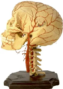
and bladder function. Doctors take these symptoms very seriously because severe myelopathy that is not treated may lead to permanent nerve or spinal cord damage. Pressure on nearby nerve roots can cause radiculopathy and may produce pain, weakness, or sensory changes in the area supplied by nerves that go from the cervical spine to the shoulder, arm, or hand. The disk acts as a shock absorber between the bones in the neck. In cervical disk degeneration the normal gelatin-like center of the disk degenerates and the space between the vertebrae narrows. As the disk space narrows, added stress is applied to the joints of the spine causing further wear and degenerative disease. The cervical disk may also protrude and put pressure on the spinal cord or nerve roots when the rim of the disk weakens. This is known as a herniated cervical disk. The neck is so flexible and it supports the head, it is extremely vulnerable to injury. Motor vehicle or diving accidents, contact sports, and falls may result in neck injury. The regular use of safety belts in motor vehicles can help to prevent or minimize neck injury. A "rear end" automobile collision may result in hyperextension, a backward motion of the neck beyond normal limits, or hyper flexion, a forward motion of the neck beyond normal limits. The most common neck injuries involve the soft tissues: the muscles and ligaments. Severe neck injuries with a fracture or dislocation of the neck may damage the spinal cord and cause paralysis. The main focus of this work is to automatically detect the reason for neck pain from plain diagnostic x-rays using a series of sequential steps. Fig.1 shows the schematic diagram of Human neck.
Fig. 1. Human neck Bones
A. BONE SPURS IN THE BACK AND NECK
B. NECK BONES
There are 7 vertebrae (bones) in the neck.
Together they form the upper-most section of the vertebral column which is known as the "cervical spine".
They are labelled C1 to C7 with C1 at the top and C7 furthest from the head and adjoining the first vertebra of the next section of the spine.
Only two of the vertebrae of the cervical spine also have individual names. They are C1 which is called the
"Atlas" bone, and C2 which is called the "Axis" bone. The atlas and axis bones are labelled on the diagram (above-right).
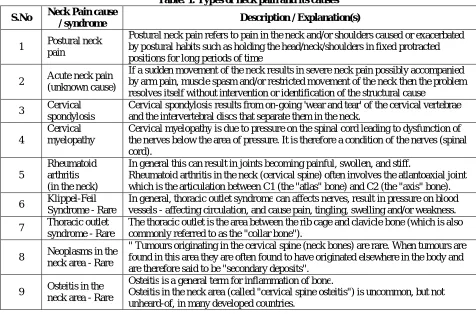
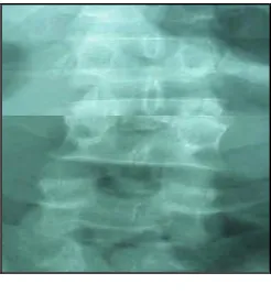
Table 1. Shows the types of neck pains an its causes and Figure 2 shows the description of the neck image. Figure 3 Shows the CT scan Human neck image.
Table. 1. Types of neck pain and its causes
S.No Neck Pain cause
/ syndrome Description / Explanation(s)
1 Postural neck pain
Postural neck pain refers to pain in the neck and/or shoulders caused or exacerbated by postural habits such as holding the head/neck/shoulders in fixed protracted positions for long periods of time
2 Acute neck pain (unknown cause)
If a sudden movement of the neck results in severe neck pain possibly accompanied by arm pain, muscle spasm and/or restricted movement of the neck then the problem resolves itself without intervention or identification of the structural cause
3 Cervical spondylosis
Cervical spondylosis results from on-going 'wear and tear' of the cervical vertebrae and the intervertebral discs that separate them in the neck.
4
Cervical myelopathy
Cervical myelopathy is due to pressure on the spinal cord leading to dysfunction of the nerves below the area of pressure. It is therefore a condition of the nerves (spinal cord).
5
Rheumatoid arthritis (in the neck)
In general this can result in joints becoming painful, swollen, and stiff.
Rheumatoid arthritis in the neck (cervical spine) often involves the atlantoaxial joint which is the articulation between C1 (the "atlas" bone) and C2 (the "axis" bone).
6 Klippel-Feil Syndrome - Rare
In general, thoracic outlet syndrome can affects nerves, result in pressure on blood vessels - affecting circulation, and cause pain, tingling, swelling and/or weakness.
7 Thoracic outlet syndrome - Rare
The thoracic outlet is the area between the rib cage and clavicle bone (which is also commonly referred to as the "collar bone").
8 Neoplasms in the neck area - Rare
" Tumours originating in the cervical spine (neck bones) are rare. When tumours are found in this area they are often found to have originated elsewhere in the body and are therefore said to be "secondary deposits".
9 Osteitis in the neck area - Rare
Osteitis is a general term for inflammation of bone.
Vol. 6, Issue 2, February 2017
Fig. 2. Description of the neck
Fig. 3. CT Scan neck image
The empirical quantities of the spinal components used in shirazi-Adl’s study [6] are shown in Table 1.
Table 1: Empirical Quantities of Spine
Material Young’s Modulus (Mpa)
Cross Section Area(mm2)
Anterior Longitudinal 7.8 63.7 Posterior Longitudinal 10 20.0 Ligamentum Flavum 15 40.0 Transverse 10 3.60
Capsular 705 60.0
model, the more accurate it is. The material properties, displacements and other system characteristics are represented by mathematical functions between nodes. This finite element model can then be used to determine the stress, strain, and displacement of the structure resulting form external loading [5]. Once the Finite Element Model has been created and the system characteristics have been established in the model, a global stiffness matrix can then be formed for the whole structure. Given the forces and boundary conditions, the unknown displacements at each of the node points can then be used to determine the stresses and strains acting on each element [5]. Initially, the Finite Element Models have been applied to aircraft structures and then FEM rapidly spread to Civil Engineering and Mechanical Engineering. FEM is gaining acceptance as a valuable tool to study static, dynamic as well as cyclic problems. Only recently FEM has been seriously applied to Biomechanical problems.
The following assumptions are made while modelling FSU:
1. Vertebrae is considered as having elliptical cross section. Actually this is an improvement over Hutchinson-Littlefield model [8]. Ellipse gives a closer approximation.
2. Upright standing posture is assumed for modelling.
With the advent of Magnetic resonance imaging (MRI), one can measure internal organs and bones with high resolution and accuracy. MRI is a non-invasive imaging approach. Cross sectional size of L1 lumbar vertebra are measured from an adult subject using MRI scan. It is found to be 40mm Major and 32 mm minor. Based on the anthropometric proportions, other dimensions are arrived at.
There are host of software for 3D modelling and here Pro/Engineer is preferred because of its simplicity and seamless integration with analysis package Pro/ Mechanica. Whole FSU is modelled in parts and assembled according to the properties of Lumbar spine. Assembled model is transferred to Pro/Mechanica environment.
Vol. 6, Issue 2, February 2017
From the above conditions forces along spine direction are F – ES - Bcos - W cos = 0 --- (1)
Moment: ES x l = Bb+ Ww ---- (2)
Where,
ES = Erector spinae muscle force F = Disc compressive force B = Force from upper body weight W = Force from lifted weight l = Length of moment arm from ES
b = Length of moment arm from centre of gravity of the body weight w = Length of moment arm from lifted weight
= Angle made by the force of body weight with erector spinae muscle force B = 0.65 x M x g
Where,
M = The body mass of the individual g = Acceleration due to gravity
From literature, for a grown up normal adult l = 6 cm, b = 25 cm
= 520 (Helander et al 1984) Let,
w = 40 cm, M = 63 Kg
III. RESULTS AND DISCUSSION
developed. The finite element model of the FSU is found to confirm with the earlier works using cadaveric method [8], thus proving the usefulness of this methodology for biomechanical modelling. The effort to be taken for the in vivo and in vitro data collection and analysis are reduced multi fold in the finite element modelling. The study can be extended to include the loading of the muscles. Same FE model can be extended to all Sagittal plane lifting activity. Thus, the study established the viability of FEM methodology for analysing FSU.
REFERENCES
1. International Commission on Radiological Protection (2000) Managing patient dose in computed tomography. ICRP publication 87. Pergamon Press, Oxford
2. Mettler FA, Wiest PW, Locken JA, Kelsey CA (2000) CT scanning: patterns of use and dose. J Radiol Prot 20:353–359
3. International Commission on Radiological Protection (1990) Recommendations of the International Commission on Radiological Protection. ICRP publication 60. Pergamon Press, Oxford
4. Hall EJ (2000) Radiobiology for the radiologist, 5th edn. Lippincott Williams & Wilkins, Philadelphia 5. Fearon T, Vunich J (1987) Normalized pediatric organ-absorbed doses from CT examinations. AJR Am J Roentgenol 148:171–174
6. Zankl M, Panzer W, Petousi-Henb N, Drexler G (1995) Organ doses for children from computed tomographic examinations. Radiat Prot Dosimetry 57:393–396
7. Brenner DJ, Elliston CD, Hall EJ, Berdon WE (2001) Estimated risks of radiation-induced fatal cancer from pediatric CT. AJR Am J Roentgenol 176:289–296
8. Tzedakis A, Damilakis J, Perisinakis K, Stratakis J, Gourtsoyiannis N (2005) The effect of z overscanning on patient effective dose from multidetector helical computed tomography examinations. Med Phys 32:1621–1629
9. Boone JM, Seibert JA (1997) An accurate method for computer-generating tungsten anode X-ray spectra from 30 to 140 kV. Med Phys 24:1661– 1670
10. Eckerman KF, Cristy M, Ryman JC (1996) The ORNL mathematical phantom series. Oak Ridge National Laboratory, Oak Ridge, Tenn 11. Siemens (2002) SOMATOM Sensation 16 application guide: routine protocols.Siemens, Forchheim
12. National Council on Radiation Protection and Measurements (1985) Induction of thyroid cancer by ionizing radiation. NCRP report 80. NCRP Publications: Bethesda, Maryland
13. Hohl C, Muhlenbruch G, Wildberger JE, Leidecker C, Suss C, Schmidt T, Gunther RW, Mahnken AH (2006) Estimation of radiation exposure in low-dose multislice computed tomography of the heart and comparison with a calculation program. Eur Radiol 16:1841–1846
14. Theocharopoulos N, Perisinakis K, Damilakis J, Karampekios S, Gourtsoyiannis N (2006) Dosimetric characteristics of a 16-slice computed tomography scanner. Eur Radiol Apr 22; [Epub ahead of print] DOI http://dx. doi.org/10.1007/s00330-006-0251-0
15. Vock P (2005) CT dose reduction in children. Eur Radiol 15:2333–2340
16. Bacher K, Bogaert E, Lapere R, De Wolf D, Thierens H (2005) Patientspecific dose and radiation risk estimation in pediatric cardiac catheterization. Circulation 111:83–89
17. Mazonakis M, Damilakis J, Raissaki M, Gourtsoyiannis N (2004) Radiation dose and cancer risk to children undergoing skull radiography. Pediatr Radiol 34:624–629