Design Analysis of a Semi-Circular Floral Shaped Directional UWB
Antenna Integrated with Wireless Multiband Applications
Madan L. Meena* and Asheesh Gupta
Abstract—This work presents a novel structure of semi-circular floral shape slotted antenna for an ultra-wideband (UWB) including WCDMA, Bluetooth and Wi-Max applications. Initially, a semi-circular floral shape radiator is designed by inserting an elliptical slot in patch with partial rectangular ground plane. Further, three rectangle symmetrical stepped slots are inserted in ground below 50 ohm micro-strip (MS) feed line which is integrated with stepped quarter wave transformer to achieve an ultra-wide impedance bandwidth. The proposed antenna structure achieves UWB of 4–18 GHz which cover 127% (S11 < −10 dB) fractional bandwidth (FBW). Furthermore, ground plane is modified by loading three asymmetrical capacitive folded strip resonators (CFSR), which provide an additional lower frequency communication bands 2100 MHz (2–2.2 GHz), 2400 MHz (2.34–2.47 GHz), and 2700 MHz (2.69–2.75 GHz) for applications of WCDMA, Bluetooth, and Wi-Max, respectively. An optimized dimension of the proposed antenna is 30×30 mm2 (1.1λ0×1.1λ0), which is designed and fabricated on an FR-4 substrate having thickness 1.6 mm and dielectric constant 4.3. The proposed design is computed by Electromagnetic (EM), ADS simulator, and simulation results are validated with measured results.
1. INTRODUCTION
Recently, the demand of ultra-wideband (UWB) antenna is increased day by day in modern communication system. Federal Communications Commission (FCC) released an unlicensed UWB 3.1–10.6 GHz for commercial applications [1]. Compact size, matching bandwidth, and stable radiation characteristics are main challenges for the design of UWB antennas. Presently, compact single antennas are the major requirement for modern communication systems to cover the entire allotted wireless communication bands.
In recent years, the design of dual-band antenna with UWB has an active research area without affecting UWB performance [2–9]. A number of dual-band antennas have been reported by researchers having UWB characteristics. Chu and Ye, Yildirim et al., and Gupta [10–12] proposed 42×46 mm2 wideband antennas having lower frequency bands, but size of these antennas is large. However, a few UWB antennas have also been proposed with the integration of low frequency wireless bands. Antoniades and Eleftheriades, Samadi Taheri et al., and Mishra et al. [13–15] designed a fork shaped, L-shaped and rhomboidal monopole multiband antennas with attaching extra loaded strips, but these antennas did not have UWB characteristics.
Further, Bod et al. and Foudazi et al. [16, 17] proposed 25×28 mm2 antennas with compact size, but bandwidth is very small. Rahanandeh et al. and Li et al. [18, 19] designed a dual-band compact antenna by loading three additional strips to cover Wi-Max, WLAN, and Bluetooth frequency bands, but the antenna did not cover the entire UWB. Aravind et al. [20] designed a rectangle patch with a coupled folded stub for UWB and long-term evaluation system, but the antenna size is very large. Mahamine et al. and Naidu [21–23] proposed a circular ring with triangular and arc-shaped antennas
Received 3 November 2018, Accepted 3 January 2019, Scheduled 1 March 2019
* Corresponding author: Madan Lal Meena ([email protected]).
for lower frequency bands of Bluetooth, WLAN, and UWB applications, then a rectangular strip is inserted for GSM band. Recently, Pahad Singh and Sahu [24] proposed a cylindrical dielectric resonator UWB antenna having multi-bands for cognitive radio application, but the antenna has small fractional bandwidth of 120% (3–12 GHz). Further, El.-Khamy et al. [25] designed a circular patch antenna with a fractal shape tree structure for UWB and 5G multi-band applications, but the antenna has very large size 90×110 mm2. In view of the above literature, most of the antenna structures focus on integration of UWB with less than two or three wireless communication bands. However, three or more integrated bands are difficult to achieve due to robust coupling between different radiating elements in ground as well as patch. Therefore, three capacitive folded strip resonators (CFSR) have been integrated with partial ground to create more than two wireless communication bands having UWB characteristics.
In this paper, a novel semi-circular floral shape slotted (SCFSS) antenna is designed to cover a UWB frequency. Multi-band applications are achieved by integrating quarter wavelength folded (meander) strip resonators on the top corner of rectangle partial ground plane. The proposed design achieves 127% fractional bandwidth in the frequency band of 4–18 GHz with covering additional wireless bands of 2–2.2 GHz, 2.34–2.47 GHz, and 2.69–2.75 GHz which are applicable to WCDMA, Bluetooth, and Wi-Max, respectively. Equivalent circuit model of the proposed design is constructed. Further, antenna dimension, bandwidth, gain, and fractional bandwidth (FBW) are compared with previously reported antennas in literature [16–24]. The optimized dimension is simulated and validated by experimental results.
The proposed work is planned as follows. Antenna configuration, design method, and parametric analysis with equivalent circuit model are elaborated in Section 2. Measured results and discussions are reported in Section 3. Finally, conclusions are summarized in Section 4.
2. PROPOSED ANTENNA CONFIGURATION, DESIGN METHOD, AND PARAMETRIC ANALYSIS
2.1. Proposed Antenna Configuration
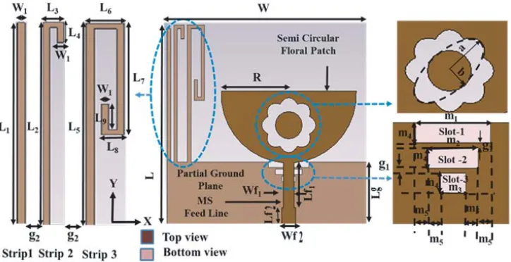
The proposed UWB antenna structure is illustrated with labeled dimensions in Fig. 1. The designed antenna is fabricated on a very low cost FR-4 substrate having thickness (height) 1.5 mm, dielectric constant (εr) 4.3, and loss tangent (tanδ) 0.025. The antenna consists ofR radius semi-circular patch,
floral shaped slot, partial rectangle ground plane with symmetrical stepped slots, and three asymmetrical capacitive folded strip resonators. Three optimized stepped rectangle slots are inserted in the ground plane. These rectangle step wise slots are inserted below the 50 Ω MS feed line which is integrated with stepped quarter wave transformer for matching purpose. The optimized lengths of stepped slot-1, slot-2,
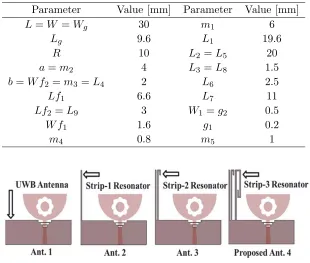
Table 1. Optimized parameters of proposed antenna.
Parameter Value [mm] Parameter Value [mm]
L=W =Wg 30 m1 6
Lg 9.6 L1 19.6
R 10 L2 =L5 20
a=m2 4 L3 =L8 1.5
b=W f2=m3 =L4 2 L6 2.5
Lf1 6.6 L7 11
Lf2=L9 3 W1=g2 0.5
W f1 1.6 g1 0.2
m4 0.8 m5 1
Figure 2. Evolution stages of proposed antenna.
and slot-3 are m1, m2, and m3, respectively. An equal separation is maintained between symmetrical stepped slots to achieve UWB impedance matching. The optimized width and separation between slots arem4 andg1, respectively. Further, ground plane is modified by loading three asymmetrical capacitive folded (meander) strip resonators (CFSR). Two meander strips and one simple strip resonators are situated along y-axis (vertically) with different separations of dimensionsg2 and g3 on the top edge of ground plane featuring compact and easy configuration. The length and width of substrate areL and
W, respectively. Therefore, overall dimension of the proposed antenna is 30×30 mm2 (1.1λ0 ×1.1λ0, where λ0 is the free space wavelength at the lowest resonant frequency 4.4 GHz). Optimized design parameters of the proposed antenna structure subsequent to simulation on EM simulator (CSTMS) are specified in Table 1.
Evaluation procedure of the proposed antenna illustration is illustrated in four stages as sketched in Fig. 2. Initially, an R radius SCFSS antenna is designed by inserting an elliptical slot in the patch with optimized partial rectangular ground plane Lg×Wg without capacitive folded strips as depicted
Figure 3. Return loss (|S11|dB) vs. frequency plot for different configuration of Ant. 1–4.
Figure 4. Simulated gain (dBi) vs. frequency plot for different arrangement of Ant. 1–4.
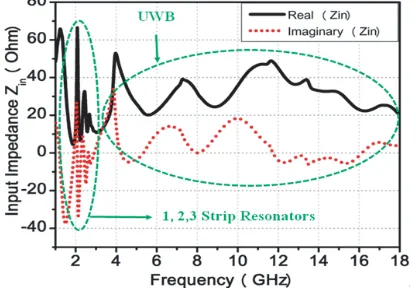
Figure 5. Input impedance (ohm) vs. frequency plot of proposed antenna.
with strip gap of g3, then antenna revolves into the proposed antenna as shown in Fig. 2 separately [see Ant. 4]. The proposed antenna supports one more additional resonant mode at 2.1 GHz while a resonance of Ant. 2 and Ant. 3 remains unchanged. Further, it can be seen that strip resonators work separately and are tuned with impedance bandwidth individually.
Return loss (|S11|dB) and gain (dBi) plots are shown in Figs. 3 and 4 for different configurations of Ant. 1–4, respectively. Further, comparative analyses of −10 dB bandwidth, FBW, and gain variations of step by step antenna configuration are given in Table 2. The proposed antenna resonant modes are investigated by plotting the real{Re(Zin)}and imaginary{Im(Zin)}parts of simulated input impedance
vs. frequency curve, shown in Fig. 5. It can be observed that the arrow marked region exhibits the resonance property of antenna as it has approximately 50 ohm real (resistance) with extremely small (i.e., nearly zero) imaginary (reactance) part of Zin and generates resonant modes at 2.1, 2.4, 2.72, 4.4,
7.7, 13, 14.5, and 17.5 GHz, respectively.
Figure 6. Equivalent circuit model of SCFSS antenna (where Lf = 0.35 nH, Cf = 1.45 pF, Cg= 0.30 pF,Lp = 0.20 nH,Cp = 1 pF,Rs1 =Rs3 =Rg1 =Rg3= 5 Ω,Rs2=Rg2 = 4 Ω,Ls1= 0.30 nH,
Cs1= 0.80 pF,Ls2 = 0.32 nH,Cs2= 0.85 pF, Ls3 = 0.35 nH,Cs3 = 0.90 pF,Lg1 = 1 nH,Cg1 = 0.20 pF,
Lg2= 2 nH, Cg2 = 0.25 pF,Lg3 = 2.5 nH,Cg3 = 0.50 pF).
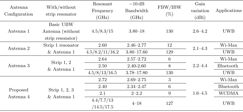
Table 2. Comparative analysis of bandwidth (S11 <−10 dB), gain variations of step by step antenna configurations.
Antenna Configuration
With/without strip resonator
Resonant Frequency
(GHz)
−10 dB Bandwidth
(GHz)
FBW/IBW (%)
Gain variation
(dBi)
Applications
Antenna 1
Basic UBW Antenna (without
strip resonator)
4.5/8.3/15 3.80–18 130 2.6–4.2 UWB
Antenna 2 Strip 1 resonator & Antenna 1
2.60 2.46–2.77 12
2.1–4.3 Wi-Max
4.5/8.2/11/16.2 3.80–17.60 129 UWB
Antenna 3 Strip 1, 2 & Antenna 1
2.64 2.57–2.72 6
2.2–4.4
Wi-Max
2.50 2.40-2.60 8 Bluetooth
4.5/8/13/16.5 3.78–17.80 130 UWB
Proposed Antenna 4
Strip 1, 2, 3 & Antenna 1
2.72 2.69–2.75 3
1.6–4.5
Wi-Max
2.40 2.34–2.47 6 Bluetooth
2.1 2–2.2 9 WCDMA
4.4/7.7/13
/14.5/17.5 4–18 127 UWB
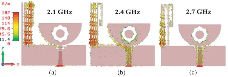
within same phase which indicates that the 2nd resonant mode is animated at 2.4 GHz. Lastly, the 3rd resonant mode is excited due to strip-1 resonator at about 2.7 GHz as shown in Fig. 7(c). Hence, it can be concluded that the lengths of added folded strip resonators individually control the 1st, 2nd, and 3rd resonant modes, and it is reported hypothetically in Subsection 2.2.
2.2. Design Method for the Proposed Antenna
The following steps are involved in the design of the proposed antenna:
(a) (b) (c)
Figure 7. Surface current distributions of the designed antenna at different frequencies (a) 2.1 GHz; (b) 2.4 GHz; (c) 2.7 GHz.
together. Major and minor axes of ellipse are inserted based on equation:
x2
a2 +
y2
b2 = 1 (1)
where aand b are lengths of major and minor axes besidex and y directions, respectively. Major and minor axes of ellipse area= 4 mm andb= 2 mm, respectively.
Step II: Further, radius of semi-circular floral shaped (SCFS) antenna is calculated by Equations (2) and (3) subsequently to confirm the estimated lowest resonant frequency for a given dielectric constant of substrate:
R = 92×10 9
fr√εeff (2)
εeff ≈ εr+ 1
2 (3)
Step III: Furthermore, the length of the nth λg/4 strip resonator is calculated through corresponding resonant frequency (frn). The total lengthLsn of strip depends on its resonant frequency and effective dielectric constant εeff of substrate which is estimated by equation as:
Lsn= c
4frn√εeff
, n= 1,2,3. . . (4)
where cand λg are the light speed and guided wavelength, respectively. Lsn= total length of thenth strip resonator which is accountable for resonant frequency.
To ensure the utility of design method, a semi-circular floral shape slotted antenna for a specified lower resonant frequency fr of 4.4 GHz is designed first. The calculated value of antenna radius R is approximately 10.4 mm, whereas simulated value is 10 mm which is very close to calculated value. The designed antenna produces the 1st resonance due to strip-3 resonator as the surface current observed in Fig. 6(a). As can be seen, the current length will be one by fourth of guided wavelength λg/4 into
medium. For the 1st resonance, the total length of strip-3 resonator can be calculated by equation:
Ls3 =L5+L6+L7+L8+L9 ≈λg/4 (5)
From Table 1, Ls3 = 38 mm, andεeff calculated by Eq. (3) is 2.65. Hence, the calculated 1st resonant
frequency is fr1 = 1.81 GHz. However, simulated resonance occurs at 2.1 GHz, and it is approximately equal to designed value. Further, the 2nd resonance is energized on account of strip-2 resonator. For the 2nd resonance, the total length of strip-2 resonator can be decided by equation:
Ls2=L2+L3+L4 ≈λg/4 (6)
From Table 1,Ls2= 23.5 mm. Thus, the calculated 2nd resonant frequency isfr2= 1.97 GHz. However, simulated resonant occurs at 2.4 GHz, and it is approximately equal to designed value. Furthermore, the 3rd resonance is energized on account of strip-1 resonator. For the 3rd resonance, the total length of strip-1 resonator can be decided by equation:
From Table 1,Ls1= 19.6 mm. Thus, the calculated 3rd resonant frequency isfr3= 2.36 GHz. However, simulated resonance occurs at 2.72 GHz, and it is approximately equal to designed value. Therefore, the design procedure for the proposed antenna is validating by a full wave simulation approach. Hence, the antenna configuration justifies theoretical perception.
2.3. Parametric Investigation
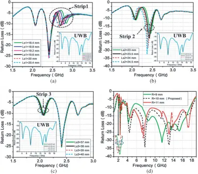
A parametric investigation is carried out to realize the belongings of resonance parameters on antenna performance. The effect of length Ls1 of strip-1 resonator, Ls2 of strip-2 resonator, Ls3 of strip-3 resonator, and semi-circular radius R of radiator are enough to optimize the performance of antenna impedance characteristics as shown in Fig. 8. For the third resonator, the effect of lengthLs1 of strip-1 resonator on return loss is shown in Fig. 8(a). It can be observed that when length Ls1 is increased from 18.4 to 20.4 mm other parameters are stable. It is established that the resonant frequencyfr3 is decreased from 2.84 to 2.63 GHz while the first and second resonant frequencies (fr1&fr2) and antenna UWB remain unchanged as can be seen in Fig. 8(a). This indicates that the third resonant frequency
fr3 having UWB frequency band can be efficiently restricted by varying length Ls1. Therefore, the optimized length Ls1 = 19.6 mm is preferred to cover the entire Wi-Max band. Further, the resonant frequencyfr3 as an occupation ofLs1 is specified in Table 3. It can be observed that the calculated fr3 is nearly in accordant with simulated frequency.
(a) (b)
(c) (d)
Table 3. Third resonant frequency fr3 changes with strip-l length.
L1, [mm] Ls1, [mm]
fr3, [GHz]
Design Eq. (7) Simulated
18.4 18.4 2.70 2.84
18.8 18.8 2.63 2.79
19.2 19.2 2.55 2.74
19.6 19.6 2.36 2.72
20 20 2.20 2.66
20.4 20.4 2.05 2.63
Further, the effect of length Ls2 of strip-2 resonator on return loss is shown in Fig. 8(b). When lengthLs2 is increased from 23 to 24.5 mm, remaining parameters are kept stable. It is established that the resonant frequency fr2 is decreased from 2.49 to 2.30 GHz, and fr1 is also shifted down from 2.18 to 2.01 GHz while the third resonant frequency fr3 and antenna UWB remain unaffected. It means that the first and third resonant frequencies (fr1, fr2) having UWB frequency band can be efficiently restricted by varying length Ls2. Therefore, the optimized lengthLs2 = 23.5 mm is preferred to cover the entire Bluetooth band. The first resonant frequency fr1 is varied as Ls2 changes due to the effect of coupling capacitance between strips. Further, the resonant frequencyfr2 as an occupation of Ls2 is specified in Table 4. It can be observed that the calculated fr2 is nearly in accordant with simulated frequency.
Table 4. Second resonant frequency fr2 changes with strip-2 length.
L4, [mm] Ls2, [mm]
fr2, [GHz]
Design Eq. (6) Simulated
13.4 23 2.01 2.49
12.8 23.5 1.96 2.40
12.2 24 1.92 2.35
11.6 24.5 1.88 2.30
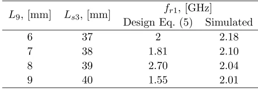
Furthermore, the effect of length Ls3 of strip-3 resonator on return loss is shown in Fig. 8(c). When lengthLs3 is increased from 37 to 40 mm, remaining parameters are kept stable, it is found that the resonant frequencyfr1 is decreased from 2.18 to 2.01 GHz, while fr2, fr3 resonant frequencies and antenna UWB remain unchanged. It means that the first resonant frequency along with UWB frequency band can be well constrained by varying length Ls3. Therefore, the optimized length Ls3 = 38 mm is preferred to cover the entire WCDMA band. Further, the resonant frequency fr1 as an occupation of Ls3 is specified in Table 5. It can be observed that the calculated fr1 is nearly in accordant with simulated frequency.
Table 5. First resonant frequencyfr1 changes with strip-3 length.
L9, [mm] Ls3, [mm]
fr1, [GHz]
Design Eq. (5) Simulated
6 37 2 2.18
7 38 1.81 2.10
8 39 2.70 2.04
Furthermore, by varying the radius of semi-circular radiator R, subsequently the first resonance and resonances of UWB are mostly affected as can be seen in Fig. 8(d) due to the effect of coupling capacitance created between radiator and strip-3 resonator. When radius R varies from 9 to 11 mm,
fr1 shifts towards lower sides, and higher cutoff frequency of UWB shifts towards advanced side by a factor of 0.1 GHz. It is mainly indicated that the first resonance frequency fr1 beside UWB can be efficiently restricted by varyingR. Therefore, the optimizedR= 10 mm is chosen to cover all preferred operating frequency bands. In view of the above parametric investigation, it can be concluded that the individually added strips resonators can be tuned separately without affecting UWB characteristics and acquire an individual resonant frequency according to the calculated strips length.
3. MEASURED RESULTS AND DISCUSSIONS
In order to validate optimized dimensions of the proposed SCFSS antenna with capacitive folded strip resonators, the antenna is fabricated or printed on a low cost FR-4 substrate through caddo-71 prototype machine as shown in Fig. 9. The antenna return loss (S11) is measured on ENA series vector network analyzer, set up as shown in Fig. 9(c). Fig. 10 shows the measured and simulated return losses vs. frequency variation of designed antenna. As can be observed in Fig. 10, there is a fine conformity between measured and simulated results with slight variations due to uncertainties in dielectric material, fabrication constrains, thickness of substrate, and effects of soldering of SMA connector. The proposed antenna resonates at 2.1, 2.4, 2.7, 4.4, 7.7, 13, 14.5, 17.5 GHz frequencies and covers three separate lower frequency communication bands 2100 MHz (2–2.2 GHz), 2400 MHz (2.34–2.47 GHz), 2700 MHz (2.69–
(a) (b) (c)
Figure 9. Proposed SCFSS antenna photographs: (a) Front view; (b) Back view; (c)S11measurement on VNA setup.
Figure 10. Measured and simulated return loss (|S11|dB) vs. frequency plot for proposed SCFSS antenna.
2.75 GHz) along with UWB 4–18 GHz with respect to suitable resonant frequencies belowS11<−10 dB point, and their respective FBWs are 9, 6, 3, and 127%.
The fabricated antenna gain and radiation pattern measurements are carried out in an anechoic chamber through LB10180 reference antenna (broadband horn antenna). The simulated and measured gains vs. frequency variation is shown in Fig. 11. The measured gain deviation for strip-3 frequency band 1.6–2.3 dBi, for strip-2 frequency band 2.2–2.7 dBi, for strip-1 frequency band 2.1–2.5 dBi and for UWB 2.5–4.4 dBi is obtained by gain disparity less than±0.5 dBi. The measured peak gains 1.60, 2.78, 2.14, 2.74, 4.40, 3.50, 4, and 3.50 dBi are obtained about 2.1, 2.4, 2.7, 4.4, 7.7, 13, 14.5, and 17.5 GHz resonant frequencies, respectively.
(a) (b) (c)
(d) (e) (f)
Figure 12. Simulated and measured radiation patterns of proposed SCFSS antenna at different resonant frequencies: (a) 2.1 GHz: (b) 2.4 GHz; (c) 2.7 GHz; (d) 4.4 GHz; (e) 7.7 GHz; (f) 14.5 GHz at Θ = 90◦ inxy-plane.
(a) (b) (c)
The measured and simulated radiation patterns of the proposed antenna at resonant frequencies of 2.1, 2.4, 2.7, 4.4, 7.7, and 14.5 GHz are shown in Fig. 12, respectively in the xy-plane at Θ = 90◦. As can be observed, there is a fine conformity between measured and simulated patterns with slight variation, and the antenna has nearly directional characteristics due to increased current density on above mentioned resonant frequencies of Bluetooth, Wi-Max including UWB. Further, the corresponding 3D-radiation patterns of the proposed antenna are shown in Fig. 13. It can be observed that the omnidirectional radiation pattern is obtained at 2.1 GHz frequency; it is matched with Fig. 12(a). Similarly, the maximum directivity/gain/radiation intensity can be observed in particular directions as shown in Figs. 13(b), (c) at 2.7 GHz and 7.7 GHz resonant frequencies, which are verified with Figs. 12(c),
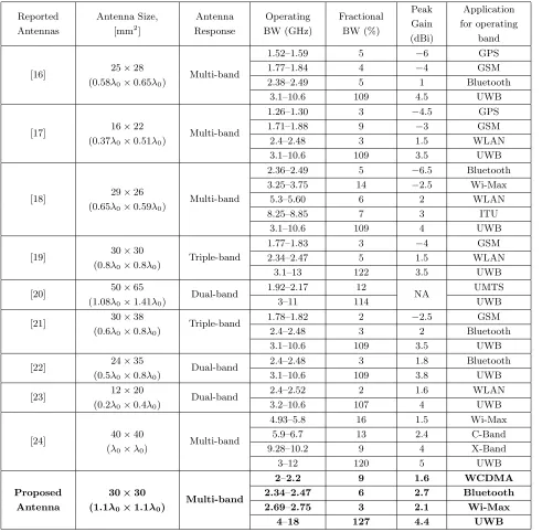
Table 6. Comparative performance analysis of proposed SCFSS antenna with existing reported antennas.
Reported Antennas
Antenna Size, [mm2]
Antenna Response Operating BW (GHz) Fractional BW (%) Peak Gain (dBi) Application for operating band
[16] 25×28
(0.58λ0×0.65λ0) Multi-band
1.52–1.59 5 −6 GPS
1.77–1.84 4 −4 GSM
2.38–2.49 5 1 Bluetooth
3.1–10.6 109 4.5 UWB
[17] 16×22
(0.37λ0×0.51λ0) Multi-band
1.26–1.30 3 −4.5 GPS
1.71–1.88 9 −3 GSM
2.4–2.48 3 1.5 WLAN
3.1–10.6 109 3.5 UWB
[18] 29×26
(0.65λ0×0.59λ0) Multi-band
2.36–2.49 5 −6.5 Bluetooth
3.25–3.75 14 −2.5 Wi-Max
5.3–5.60 6 2 WLAN
8.25–8.85 7 3 ITU
3.1–10.6 109 4 UWB
[19] 30×30
(0.8λ0×0.8λ0) Triple-band
1.77–1.83 3 −4 GSM
2.34–2.47 5 1.5 WLAN
3.1–13 122 3.5 UWB
[20] 50×65
(1.08λ0×1.41λ0) Dual-band
1.92–2.17 12
NA UMTS
3–11 114 UWB
[21] 30×38
(0.6λ0×0.8λ0) Triple-band
1.78–1.82 2 −2.5 GSM
2.4–2.48 3 2 Bluetooth
3.1–10.6 109 3.5 UWB
[22] 24×35
(0.5λ0×0.8λ0) Dual-band
2.4–2.48 3 1.8 Bluetooth
3.1–10.6 109 3.8 UWB
[23] 12×20
(0.2λ0×0.4λ0) Dual-band
2.4–2.52 2 1.6 WLAN
3.2–10.6 107 4 UWB
[24] 40×40
(λ0×λ0) Multi-band
4.93–5.8 16 1.5 Wi-Max
5.9–6.7 13 2.4 C-Band
9.28–10.2 9 4 X-Band
3–12 120 5 UWB
Proposed Antenna
30×30
(1.1λ0×1.1λ0) Multi-band
2–2.2 9 1.6 WCDMA
2.34–2.47 6 2.7 Bluetooth
2.69–2.75 3 2.1 Wi-Max
(e). However, the UWB antenna must radiate uniformly throughout the band, but radiation pattern of the proposed antenna highly depends on its operating frequency. Therefore, the radiation pattern is slightly varied within the band that can be verified from Fig. 12. Furthermore, the proposed antenna performance is compared in Table 6 with previously reported antennas [16–24] in terms of antenna size, antenna response,−10 dB fractional BW, peak gain, and applications of antenna operating band.
4. CONCLUSIONS
In this paper, a compact (1.1λ0 ×1.1λ0) structure of SCFSS UWB antenna with wireless multiband applications is designed, fabricated, and tested experimentally. To realize multiband characteristics, a resonator with three asymmetrical capacitive folded strips is loaded on partial ground plane for lower wireless communication bands without affecting UWB characteristics. The measured impedance bandwidth of designed UWB antenna is 4–18 GHz which covers 127% (S11 < −10 dB) fractional bandwidth (FBW). The IBWs of additional lower wireless communication bands are 2100 MHz (2– 2.2 GHz), 2400 MHz (2.34–2.47 GHz), 2700 MHz (2.69–2.75 GHz) and (4–18 GHz) which are suitable for WCDMA, Bluetooth, and Wi-Max applications, respectively. Further, antenna size, fractional bandwidth, gain performance of the antenna have also been compared with earlier reported similar research works as given in Table 6. Accordingly, the proposed antenna is compact, having multiband characteristics, high gain, and directive pattern compared with existing antennas.
ACKNOWLEDGMENT
The authors would like to acknowledge and convey their sincere thanks to Prof. S. K. Koul, Centre for Applied Research in Electronics (CARE), Indian Institute of Technology (IIT), New Delhi, India and Rajasthan Technical University, Kota, India for providing the measurement lab facilities to complete this research work.
REFERENCES
1. Federal Communications Commission, First Report and Order, 2002.
2. Chen, Z. N., T. S. P. See, and X. Qing, “Small printed ultra-wideband antenna with reduced ground plane effect,” IEEE Trans. Antennas Propag., Vol. 55, No. 2, 383–388, 2007.
3. Verbiest, J. R. and G. A. E. Vandenbosch, “A novel small-size printed tapered monopole antenna for UWB WBAN,”IEEE Antennas Wireless Propag. Lett., Vol. 5, 377–379, 2006.
4. Radiom, S., H. Aliakbarian, G. A. E. Vandenbosch, and G. G. E. Gielen, “An effective technique for symmetric planar monopole antenna miniaturization,”IEEE Trans. Antennas Propag., Vol. 57, No. 10, 2989–2996, 2009.
5. Valderas, D., R. Alvarez, J. Melendez, I. Gurutzeaga, J. Legarda, and J. I. Sancho, “UWB staircase-profile printed monopole design,” IEEE Antennas Wireless Propag. Lett., Vol. 7, 255–259, 2008. 6. Gopikrishna, M., D. D. Krishna, C. K. Anandan, P. Mohanan, and K. Vasudevan, “Design of a
compact semi-elliptic monopole slot antenna for UWB systems,” IEEE Trans. Antennas Propag., Vol. 57, No. 6, 1834–1837, 2009.
7. Abbosh, A. M. and M. E. Bialkowski, “Design of ultra-wideband planar monopole antennas of circular and elliptical shape,”IEEE Trans. Antennas Propag., Vol. 56, No. 1, 17–23, 2008.
8. Dissanayake, T. and K. P. Esselle, “UWB performance of compact L-shaped wide slot antennas,” IEEE Trans. Antennas Propag., Vol. 56, No. 4, 1183–1187, 2008.
9. Sagar, N. T., M. L. Meena, and P. Shukla, “Design and performance analysis of UWB circular ring antenna with defected ground structure,” ICTACT Int. J. on Communication Technology, Vol. 8, No. 4, 1656–1663, 2017.
11. Yildirim, B. S., B. A. Cetiner, G. Roquetra, and L. Jofre, “Integrated Bluetooth and UWB antenna,” IEEE Antennas Wireless Propag. Lett., Vol. 8, 149–152, 2009.
12. Gupta, R. K., “Printed tri-band monopole antenna structures for wireless applications,”Microwe. Opt. Technol. Lett., Vol. 51, No. 7, 1781–1785, 2009.
13. Antoniades, M. A. and G. V. Eleftheriades, “A compact multiband monopole antenna with a defected ground plane,” IEEE Antennas Wireless Propag. Lett., Vol. 7, 652–655, 2008.
14. Samadi Taheri, M. M., H. R. Hassani, and M. A. Nezhad, “UWB printed slot antenna with Bluetooth and dual notch bands,”IEEE Antennas Wireless Propag. Lett., Vol. 10, 255–258, 2011. 15. Mishra, S. K., R. K. Gupta, A. Vaidya, and J. Mukherjee, “A compact dual-band fork-shaped monopole antenna for Bluetooth and UWB applications,” IEEE Antennas Wireless Propag. Lett., Vol. 10, 627–630, 2011.
16. Bod, M., H. R. Hassani, and M. M. S. Taheri, “Compact UWB printed slot antenna with extra bluetooth, GSM, and GPS bands,”IEEE Antennas Wireless Propag. Lett., Vol. 11, 531–534, 2012. 17. Foudazi, A., H. R. Hassani, and S. M. A. Nezhad, “Small UWB planar monopole antenna with added GPS/GSM/WLAN bands,”IEEE Trans. Antennas Propag., Vol. 60, No. 6, 2987–2992, 2012. 18. Rahanandeh, M., A. S. N. Amin, M. Hosseinzadeh, P. Rezai, and M. S. Rostami, “A compact elliptical slot antenna for covering Bluetooth/WiMAX/WLAN/ITU,” IEEE Antennas Wireless Propag. Lett., Vol. 11, 857–860, 2012.
19. Li, G., H. Zhai, T. Li, X. Y. Ma, and C.-H. Liang, “Design of a compact UWB antenna integrated with GSM/WCDMA/WLAN bands,” Progress In Electromagnetics Research, Vol. 136, 409–419, 2013.
20. Aravind, S., S. Joseph, S. Mridula, B. Paul, and P. Mohanan, “Compact dual band antenna for UMTS/UWB,”Procedia Computer Science (Elsevier), Vol. 46, 1349–1356, 2014.
21. Mahamine, S. D. and R. P. Labade, “A design of integrated GSM and Bluetooth ultra-wide band printed monopole antenna (UWB) for wireless applications,” IEEE Bombay Section Symposium (IBSS), 1–6, 2015.
22. Mahamine, S. D., R. S. Parbat, S. H. Bodake, and M. P. Aher, “Design of Bluetooth integrated UWB printed monopole antenna for wireless application,” IEEE Int. Conf. on Automatic Control and Dynamic Optimization Techniques, 1146–1151, 2016.
23. Naidu, P. V., “Design, simulation of a compact triangular shaped dual-band microstrip antenna for WLAN and UWB applications,” Springer — Wireless Personal Communications, Vol. 95, No. 2, 783–794, 2017.
24. Pahad Singh, S. and S. Sahu, “Planar UWB integrated with multi narrowband cylindrical dielectric resonator antenna for cognitive radio application,” AEU — International Journal of Electronics and Communications, Vol. 74, 150–157, 2017.