NOVEL DESIGN OF DUAL-MODE BANDPASS FILTER USING RECTANGLE STRUCTURE
L.-P. Zhao, X. Zhai, B. Wu, T. Su, W. Xue, and C.-H. Liang
National Key Laboratory of Antennas and Microwave Technology Xidian University
Xi’an 710071,P. R. China
Abstract—A compact dual-mode filter is proposed by using rectangle structure. The filter has the characteristics of compact structure,low insertion loss and so on. Several attenuation poles in the stopband are realized to improve the selectivity of the proposed bandpass filter. The experimented results were in good agreement with simulated results.
1. INTRODUCTION
the stacked loop structure may introduce higher cost and difficulties in fabrication.
In this paper,we introduce a new microstrip rectangle loop dual-mode filter. The filter,with lower insertion loss,provides the better transmission band.
2. RECTANGLE DUAL-MODE RESONATOR
As a kind of special filters based on a variety of symmetric dual-mode resonating structuresdual-dual-mode filter can be equivalent to dual tunable resonator circuit in practical application [8,9]. Therefore, the number of the patch can be decreased 50 percent and the size of circuit can also be reduced in the current application. Based on the characteristics above,the dual-mode filter can be used sharply in miniaturized communication system.
Some people such as Wolf have advanced many designs of microstrip dual-mode bandpass filters,owning the same characteristics, which introduce asymmetry feed-lines,slots or pins and so on for a perturbation in the resonator in order to couple its two degenerate modes,with tuning the correlative parameters of circuit so as to obtain the work condition of dual-mode resonator. In the conventional design of filters,circular and square patches have used widely. The degenerate modes of a square ring are coupled by a perturbation at one or more corners of the square. However,rectangle microstrip structure was used in the design of filter in this paper for its smaller size.
Different filter responses can be obtained with different positions and sizes of the perturbation,which is analyzed in detail in [6]. According to the analysis of resonant mode theory and slow-wave effect,the function of rectangle patch is equal to cut a part of the structure [6].
The fundamental resonance occurs whenλg is the perimeter of the rectangle,where λg is the guided wavelength.
λg =
c f√εeff
(1)
3. RECTANGLE DUAL-MODE BANDPASS FILTER
Figure 1 shows the proposed rectangle structure. So far,the study of microstrip rectangle structure filters has received little attention. Based on the former concerns on filtering characteristics,a novel dual-mode bandpass filter is presented. Given the lengths of side of the structure,the waveguide wavelength corresponding to the passband is
λg1= 2(a1 +b1) (2)
wherea1,b1 are the lengths of side of the rectangle.
Figure 1. Configuration of the dual-mode bandpass filter.
The two different perturbations (the top one: a is the length of the side of the square; the bottom one: a2, b2 are the lengths of the side of the rectangle.) can change the field distribution and inspire the degenerate modes,meanwhile,the cross couplings between the degenerate modes including electric and magnetic couplings can not only generate attenuation poles but also cause the resonant frequency of higher harmonic wave to shift. In this case,it can be used for the miniaturization of the filter design.
By inserting an electric wall and a magnetic wall into the symmetry plane of the equivalent circuit,respectively,we can obtain
fe =
1
2π(L−Lm ) (C−Cm ) (3)
fm =
1
As can be known that both the magnetic and electric couplings have the same effect on the resonant frequency shifting. In other words, they reduce or enhance the stored flux or charge of the single resonant circuit at the same time when the electric wall or the magnetic wall is inserted.
From the Equations (3) and (4),we can obtain the mixed coupling coefficientkB:
kB =
fe2−fm2 f2
e +fm2
= CLm+LCm
LC+LmCm (5)
When
LmCm LC
kB≈
Lm L +
Cm C =k
M +kE (6)
Which clearly indicates that the mixed coupling is resulted from the superposition of the magnetic and electric couplings.
In this part we work with a fixed coupling topology as shown in Fig. 2.
Figure 2. Topology of the proposed filter.
For any two-port lossless filter network composed of a series ofN
intercoupled resonators,the transfer and reflection functions may be expressed as a ratio of two Nth degree polynomials
S11(ω) =
FN(ω)
EN(ω)
S21(ω) =
PN(ω)
εEN(ω)
(7)
function, ε is a constant normalizing S21 to the equiripple level at
ω=±1 as follows:
ε= 1
10RL/10−1.
PN(ω)
FN(ω)
, ω = 1 (8)
whenRLis the prescribed return loss level in decibels and it is assumed that all the polynomials have been normalized such that their highest degree coefficients are unity. S11(ω) and S21(ω) share a common denominator EN(ω),and the polynomialPN(ω) contains the transfer function transmission zeros.
Using the conservation of energy formula for a lossless network
S2
11+S212 = 1 and (3)
S212 (ω) = 1 1 +ε2C2
N(ω)
= 1
(1 +jεCN(ω)) (1−jεCN(ω))
(9)
where
CN(ω) =
FN(ω)
PN(ω)
(10)
CN(ω) is known as the filtering function of degree N and has a form for the general Chebyshev characteristic [6]
CN(ω) = cosh
N
n=1
cosh−1(xn)
(11)
where
xn=
ω−1/ωn 1−ω/ωn
(12)
and jωn = sn is the position of the nth transmission zero in the complexs-plane.
The first step in the polynomial synthesis procedure is to replace the cosh−1 term in (11) with its identity
CN(ω) = cosh
N
n=1
ln (an+bn)
(13)
where
an=xn, bn=
Then
CN(ω) = 1 2
exp ln (an+bn)
+exp −ln (an+bn) = 1 2 N n=1
(an+bn) +
1 N n=1
(an+bn)
(15)
Multiplying the second term in (11) (top and bottom) by
N
n=1(an−bn) yields
CN(ω) = 1 2
N
n=1
(an+bn) + N
n=1
(an−bn)
(16)
Because
N
n=1(an+bn).
N
n=1(an−bn) =
N
n=1
a2n−b2n (17)
In the bottom line of the second term will always be unity. This is easily verified by substituting for an and bn using (13).
Equation (9) may now be written in its final form by substituting foran,bn and xn using (11) and (13) as follows:
CN(ω) = 1 2 N n=1
(cn+dn) + N n=1
(cn−dn)
N n=1
1−ωω
n (18) where
cn=ω− 1
ωn
, dn=ω
1− 1
ω2 n
1/2
, ω =ω2−11/2 (19)
a transformed frequency variable.
According to the analysis above,the normalized coupling matrix can be synthesized as:
[M] =
4.0 4.5 5.0 5.5 6.0 6.5 7.0 -60
-50 -40 -30 -20 -10 0
S
P
ar
am
et
er
s
Frequency(GHz)
S11
S21
Figure 3. Simulation results of proposed filter.
As shown in Fig. 3,the simulated results of the proposed dual-mode filter are obtained using simulator IE3D V10 based on MOM. IE3D from Zeland Software Inc is used for this purpose as well as for the analysis and design of the filter. From which,low insertion loss,high selectivity,and good isolation characteristics can be observed clearly.
4. FABRICATE FILTER AND MEASURED RESULT
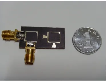
The proposed dual-mode bandpass filter is fabricated with design parameters as follows: a = 0.7 mm, a1 = 7.3 mm, b1 = 8 mm,
a2 = 0.7 mm, b2 = 0.5 mm, h1 = 0.3 mm, h2 = 0.2 mm, w2 = 1 mm,
g= 0.2 mm,andw1 = 2.8 mm is the width of 50 Ω microstrip feed-line on a 1 mm thick dielectric substrate with a relation dielectric constant of 2.65. The photograph of the fabricated filter is shown in Fig. 4.
The filter is measured with Agilent 8719ES network analyzer. The results are shown in Fig. 5. Two attenuation poles in the stopband as follows: 4.94 GHz,6.10 GHz. Return loss larger than 20 dB is achieved in the passband.
Figure 4. Photograph of the fabricated filter.
4.0 4.5 5.0 5.5 6.0 6.5 7.0
-60 -50 -40 -30 -20 -10 0
S21measurement S21simulation
S21
(d
B
)
Frequency(GHz)
Figure 5. Comparison of the simulated and measured results.
5. CONCLUSION
ACKNOWLEDGMENT
This work is supported by the National Natural Science Foundation of China (NSFC) under Contract No. 60501023.
REFERENCES
1. Levy,R.,“Zolotarev functions,a new distribution prototype filter, and the design of mixed lumped/distributed components,” IEEE G-MTT Microwave Int. Symp. Dig.,Vol. 70,71–75,1970.
2. Dai,X.-W.,C.-H. Liang,B. Wu,and J. Fan,“Novel dual-band bandpass filter design using microstrip open-loop resonators,”
Journal of Electromagnetic Waves and Applications,Vol. 22, No. 2,219–225,2008.
3. Gil,M.,J. Bonache,J. Selga,J. Garcia-Garcia,and F. Martin, “High-pass filters implemented by composite right/left handed (CRLH) transmission lines based on complementary split rings resonators (CSRRs),”PIERS Online,Vol. 3,No. 3,251–253,2007. 4. Chen,Z.-X.,X.-W. Dai,and C.-H. Liang,“Novel dual-mode dualband bandpass filter using double square-loop structure,”
Progress In Electromagnetics Research,PIER 77,409–416,2007. 5. Tu,W.-H. and K. Chang,“Miniaturized dual-mode bandpass
filter with harmonic control,” IEEE Microwave and Wireless Components Letters,Vol. 15,No. 12,December 2005.
6. Hong,J. S.,“Couplings of microstrip square open-loop resonators for cross-coupled planar microwave filters,” IEEE Transaction Microwave Theory and Techniques,Vol. 44,No. 12,December 1996.
7. Chen,J.-X. and T. Y. Yum,“Dual-mode dual-band bandpass filter using stacked-loop structure,”IEEE Microwave and Wireless Components Letters,Vol. 16,No. 9,September 2006.
8. Hong,J.-S. and S. Z. Li,“Dual-mode microstip triangular patch resonators and filters,” 2003 IEEE MTT-S Digest,1901–1904, 2003.
9. Cameron,R. J.,“Fast generation of Chebyshev filter prototype with asymmertrically-prescribed transmission zeros,” ESAJ., Vol. 6,83–95,1982.
10. Wang,J.,Y.-X. Guo,B.-Z. Wang,L. C. Ong,and S. Xiao, “High-selectivity dual-band stepped-impedance bandpass filter,”
11. Sun,S. and L. Zhu,“Novel design of dual-band microstrip bandpass filters with good in-between isolation,” IEEE. APMC 2005,Suozhou,2005.
12. Tsai,L.-C. and C.-W. Hsue,“Dual-band bandpass filters using equallength coupled-serial-shunted lines and Z-transform techniques,” IEEE Trans. Microw. Theory Tech.,Vol. 52,No. 4, 1111–1117,Apr. 2004.
13. Xiao,J.-K. and Y. Li,“Novel compact microstrip square ring bandpass filters,” Journal of Electromagnetic Waves and Applications,Vol. 20,No. 13,1817–1826,2006.
14. Chen,Y.-W.,Y.-J. Liu,and M.-H. Ho,“The quasi-elliptic bandpass filter using quarter-wavelength stepped impedance resonators,”PIERS Online,Vol. 2,No. 6,605–608,2006.
15. Lugo,C. and J. Papapolymerou,“Bandpass filter design using a microstrip triangular loop resonator with dual-mode operation,”
IEEE Microwave and Wireless Comopnents Letters,Vol. 15,No. 7, July 2005.
16. Hong,J.-S. and M. J. Lancaster,Microstrip Filters for RF/Microwave Applications,John wiley & Sons,Inc. 2001. 17. Zhao,L.-P.,X.-W. Dai,Z.-X. Chen,and C.-H. Liang “Novel
design of dual-mode dual-band bandpass filter with triangular resonators,” Progress In Electromagnetics Research,PIER 77, 417–424,2007.
18. Kazerooni,M. and A. Cheldavi,“Simulation,analysis,design and applications of array defected microstrip structure (ASMS) filters using rigorously coupled multi-strip (RCMS) method,” Progress In Electromagnetics Research,PIER 63,193–207,2006.
19. Khalaj-Amirhosseini,M.,“Microwave filters using waveguides filled by multi-layer dielectric,” Progress In Electromagnetics Research,PIER 66,105–110,2006.
20. Wang,Y. X.,B.-Z. Wang,and J. Wang,“A compact squareloop dual-mode bandpass filter with wide stopband,” Progress In Electromagnetics Research,PIER 77,67–73,2007.
21. Xiao,J.-K. and Q.-X. Chu,“Novel microstrip triangular resonator bandpass filter with transmission zeros and wide bands using fractal-shaped deffection,”Progress In Electromagnetics Research, PIER 77,343–356,2007.
22. Velazquez-Ahumada,M. C.,J. Martel,and F. Medina, “Microstrip coupled line filters with spurious band suppression,”
23. Li,C.,K. Y. Liu,and F. Li,“A microstrip highpass filter with complementary split ring resonators,” PIERS Online,Vol. 3, No. 5,583–586,2007.
24. Velazquez-Ahumada,M. C.,J. Martel-Villagr,and F. Medina, “Low-pass elliptic filters using mixed microstrip-CPW technolo-gies,”PIERS Online,Vol. 3,No. 7,997–999,2007.
25. Wu,G.-L.,W. Mu,X.-W. Dai,and Y.-C. Jiao,“Design of novel dual-band bandpass filter with microstrip meander-loop resonator and CSRR DGS,” Progress In Electromagnetics Research,PIER 78,17–24,2008.
26. Zhu,Y.-Z. and Y.-J. Xie,“Novel microstrip bandpass filters with transmission zeros,”Progress In Electromagnetics Research, PIER 77,29–41,2007.
27. Yildiz,C. and M. Turkmen,“Quasi-static models based on artificial neural neworks for calculating the characteristic parameters of multilayer cylindrical coplanar waveguide and strip line,”Progress In Electromagnetics Research B,Vol. 3,1–22,2008. 28. Abdalla,M. A. and Z. Hu,“On the study of left-handed coplanar waveguide coupler on Ferrite substrate,” Progress In Electromagnetics Research Letters,Vol. 1,69–75,2008.