Dynamic Thermal Processes in Ultra-High-Speed
Microgenerators for UAV
Flur R. Ismagilov, Viacheslav E. Vavilov, and Denis V. Gusakov*
Abstract—The paper presents a study of dynamic thermal processes in ultra-high-speed microgenerators power of 55 W with the rotational speed of 800,000 rpm for UAV. A large-scale study of current works devoted to this topic were done where the main shortcomings were identified. A mathematical description of heat exchange processes in microelectromechanical energy converters with a flight time of no more than 10 minutes was developed in a non-stationary formulation. A study of the thermal state of the microgenerator operating in a short-term mode without a special cooling system is conducted. An experimental study of the heating dynamics of its active parts is carried out using the method of physical analogies. On the basis of experimental studies, the FEMM model is verified. Afterwards, combined electromagnetic and thermal calculations of microgenerator are conducted.
1. INTRODUCTION
The creation of miniature unmanned aerial vehicles (UAV), for example Black Widow, with a wingspan up to 15 cm poses the task of developing micro-sized electric power sources with high energy density. The task of these power sources is to provide the power supply of the miniature UAV systems that ensure its functioning. Basically a Li-Ion battery is used to solve this problem. But Li-Ion batteries have a number of drawbacks, and the main one is low temperature resistance and low density of stored energy. They can quickly discharge at temperatures of −60◦C. Alternative Li-Ion batteries for power supply miniature UAV are microturbine installations with ultra-high-speed microelectromechanical energy converters (MEEC) [1]. MDOT Aeronautics and Onera DecaWatt programs are aimed at creating such energy sources for miniature UAV. Typically, the rotation speed of the MEEC varies from 300,000 to 500,000 rpm; the geometric dimensions do not exceed 20–25 mm in diameter at a weight of not more than 50–70 grams; the operating time is not more than 10–15 minutes. MEES has microscopic dimensions and works at the limit of material properties. Therefore, a change in any parameters, even by 1%, may lead to a change in the characteristics of the electric machine, which requires an increased design accuracy. This is what distinguishes MEEC from other types of electrical machines. New studies of MEEC related to non-stationary thermal processes are presented in this paper.
Power Electronic Systems Laboratory, Celeroton and ETH Zurich have developed and serially produced ultra-high-speed starter generators on permanent magnets for microturbine installations, laser systems, medical equipment and microprocessing materials. Currently, the maximum rotor rotational speed of the MEEC achieved by Celeroton is 1 million rpm [2, 3]. The capacities that are serially produced by Celeroton are from 100 W to 1 kW. In [4], electromagnetic and mechanical calculations of the MEEC with a power of 100 W, operating in the generator mode made by Celeroton are described. In [5], the topologies of the inverter for MEEC made by Celeroton are given. Zwyssig publications [2–5] cover practically all aspects of the MEEC design with a rotor speed of 500,000 rpm and 1,000,000 rpm. They list electromagnetic and mechanical calculations of MEEC and also pay attention to the thermal
Received 30 August 2017, Accepted 11 October 2017, Scheduled 25 October 2017
calculations of stationary processes in the MEEC with a frequency of 1,000,000 rpm using thermal schemes. In the work of T¨uys¨uz et al. [6], an optimal cooling system of MEEC was chosen. At the same time, the work of Celeroton does not pay attention to studies of non-stationary thermal processes in MEEC.
IHI Corporation has created a microturbine system with a microgenerator. The device contains an oil-free gas turbine with an ultra-high-speed generator integrated into it. The rotor speed of the microgenerator is 400,000 rpm, and power is 400 watts. Microgenerator type is magnetoelectric, and bearing supports are gas-dynamic [7]. IHI has paid a lot of attention to the creation of thermal resistance between the turbine and the MEEC, but the thermal investigation of the MEEC is not considered.
Robot/Mechatronics Research Center is working on the development of a microturbine plant with a 500 W microgenerator and a rotational speed of 400,000 rpm for powering UAV. The stator of this generator is made with 6 slots and 3-phase winding laid in it. The shroud of the rotor is made of the Inconel 718 alloy, and Sm2Co17 is used as the rotor magnets (bipolar system). Bearings used in this
microgenerator are gas dynamic [8]. Thermal processes in MEEC in this work are also not disclosed. Stanford University in conjunction with MDOT Aeronautics is developing an ultra-high-speed MEEC with permanent magnets with a power of 400 W and rotor speed of 800,000 rpm for UAV [9]. The publications of the team are mainly devoted to the design of the MEEC and its electromagnetic calculations. Thermal studies of MEEC are not listed.
Onera [10] has created a microturbine system with a MEEC whose dimensions do not exceed 20 mm in length and 25 mm in diameter. MEEC is made in the form of an electric machine with a slotless stator made of amorphous steel and an internal rotor with high-coercivity permanent magnets (HCPM) of Sm2Co17 brand. The power of this MEEC is 55 W at a nominal rotor speed of 840,000 rpm, and the
main purpose of this MEEC is the power supply of autonomous objects. MEEC of Onera does not have a cooling system and is operated in a short-term mode (30 minutes); the resource of this MEEC is 100 cycles.
The main attention in publications above is paid to the research of the MEEC control system, the rotor dynamics, the optimization of parameters and efficiency. However, not enough attention is paid to the thermal state of the MEEC and the processes taking place in the MEEC with the temperature change of its active parts. It is worth noting that an incorrect evaluation of the thermal state of the MEEC can lead to its overheating and failure of the entire UAV.
Our research team has faced the problem of thermal studies of MEEC when designing microgenerator for UAV with a flight time of 10 minutes and a wingspan of 15 cm. Our industrial partner has posed the task to develop a microgenerator power of 50–70 W with a rotor speed of 800,000 rpm. The microgenerator should have a minimum weight and be designed for a running time of not more than 10 minutes. In this case, the cooling system of the microgenerator was absent to minimize the weight of the UAV. We needed to study the dynamic thermal state of the MEEC during the entire UAV flight.
Studies of thermal processes in electric machines with permanent magnets are given in [6, 11–15]. In [11–13], general approaches and methods of studying thermal processes are given. Some modeling methods are used in calculating the losses and temperature distributions in electric machines with permanent magnets are given in [14]. However, this does not consider methods that allow solving the MEEC problems. Combined approaches of the thermal and electromagnetic calculations of electric machines are given in [15], but at the same time MEEC is not considered. In the work [6] by T¨uys¨uz et al., the problem of studying the steady thermal state and cooling systems of MEEC is solved using the example of an electric machine with a power of 1 kW and rotor speed of 280,000 rpm. At the same time, this paper does not pay attention to MEEC studies working in the short-term mode and to the change in losses in the elements of the MEEC under the action of temperature. These problems caused by the fact that thermal calculations of electric machines use either a thermal scheme method or FEMM methods. However, when it comes to MEEC working for short time FEMM methods and methods of thermal schemes can lead to inaccuracies especially when the problem is dynamically formulated.
dynamics of its active parts are performed using the method of physical analogies. The method of physical analogies is verified by the results of the experiment data obtained in the thesis of Zwyssig. The FEMM model is verified on the basis of experimental studies and then combined electromagnetic and thermal calculations of MEEC are conducted. In other words, this work uses the imposition of two methods of modeling — FEMM and physical analogies. The effect of the thermal state of the MEEC on its efficiency is determined based on the results of combined thermal and electromagnetic calculations. This aspect of our work is also very important for the practical design of MEEC. The temperature of stator steel, rotor magnets and winding will change since the losses will not remain constant in time with increasing temperature of the MEEC. This will lead to a change in the MEEC power during operation. These changes may not affect the work processes of traditional electric machines with large dimensions. In view of the small geometric dimensions and low power of MEEC, these changes can affect the operation process not only of the MEEC itself but also of the power supply system of the entire UAV. Therefore, they must be taken into account and evaluated already at the design stage.
This paper is structured as follows. In the first stage, thermal processes in the MEEC are described mathematically. After that, a study of the thermal state of the MEEC and the change in its losses due to temperature are performed by the method of physical analogies. Based on these changes, a combined electromagnetic model is obtained with the help of FEMM.
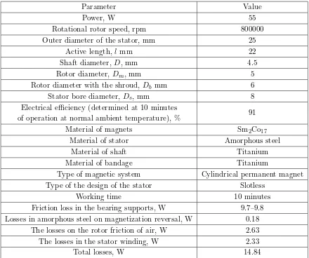
The geometric dimensions and the main losses in the elements of the studied MEEC are considered by us in [16] and presented in Table 1. Figure 1 shows the external appearance of the MEEC for a UAV.
Table 1. MEEC characteristics.
Parameter Value
Power, W 55
Rotational rotor speed, rpm 800000
Outer diameter of the stator, mm 25
Active length, l mm 22
Shaft diameter,D, mm 4.5
Rotor diameter, Dm, mm 5
Rotor diameter with the shroud,Db mm 6
Stator bore diameter,Ds, mm 8
Electrical efficiency (determined at 10 minutes
of operation at normal ambient temperature), % 91
Material of magnets Sm2Co17
Material of stator Amorphous steel
Material of shaft Titanium
Material of bandage Titanium
Type of magnetic system Cylindrical permanent magnet
Type of the design of the stator Slotless
Working time 10 minutes
Friction loss in the bearing supports, W 9.7–9.8
Losses in amorphous steel on magnetization reversal, W 0.18
The losses on the rotor friction of air, W 2.63
The losses in the stator winding, W 2.33
Figure 1. External appearance of the MEEC for an UAV. Here: A+, A−windings of phase A; B+, B−windings of phase B; C+, C−windings of phase C; Dm — rotor diameter; D — shaft diameter; Ds — stator bore diameter; Db — rotor diameter with the shroud;δ — air gap.
2. MATHEMATICAL DESCRIPTION OF PROCESSES IN MEEC
The initial stage of our research was the development of a mathematical description of heat exchange processes in MEEC. This problem was solved in a non-stationary formulation. The active part of MEEC was divided into several zones, each of which is characterized by its thermal characteristics. Then using the Fourier equations, one can describe the thermal processes for each zone.
The heat exchange between the stator winding and steel is described by a system of equations:
Pfe =cfemfe∂Θ1
∂t +αfeS1cf(Θ1−Θa.t.),
Pm =ccumcu∂∂tΘ2 +αcuScu(Θ2−Θa.t.),
S1(αfeΘ1+αcuΘ2−αcuΘa.t.−αfeΘa.t.) = 2c0Q0Θa.t..
(1)
where Pfe, Pm are the losses in the steel and winding of the stator, respectively; Q0 is the air mass
flow rate; Θ1, Θ2 are the temperature of the stator steel and winding, respectively; Θa.t.is the ambient
temperature; S1cf is the area of conjugate facets; Scu is the winding cross-sectional area; cfe, ccu, c0
are the specific heat of stator steel, stator winding and air, respectively; αfe, αcu are the heat transfer coefficient of stator steel and winding, respectively; mfe, mcu are the mass of steel stator and winding respectively; tis time.
The thermal interaction between the stator and rotor bandage is determined by a system of equations similar to Eq. (1), taking into account the detected features of the thermal processes of the MEEC:
Pfe =cfemfe∂∂tΘ1 +αfeS2(Θ1−Θa.t.),
when Pfe > Pm, cb.r.mb.r.∂
Θb.r.
∂t =−αb.r.S2(Θb.r.−Θa.t.), (2)
S2(αfeΘ1+αb.r.Θb.r.−αb.r.Θa.t.−αfeΘa.t.) = 2c0Q0Θa.t.,
Pcu=ccumcu∂Θ2
∂t +αcuS2(Θ1−Θa.t.),
when Pfe < Pm, cb.r.mb.r.∂
Θb.r.
∂t =−αb.r.S2(Θb.r.−Θa.t.), (3)
S2(αcuΘ2+αb.r.Θb.r.−αb.r.Θb.r.−αcuΘa.t.) = 2c0Q0Θa.t.,
where Θb.r. is the bandage temperature; Q0 is the air mass flow rate; mb.r. is the bandage mass;S2 is
the area of conjugate facets; cb.r. is the specific heat capacity of the bandage; αb.r. is the coefficient of
heat transfer of the bandage.
Thermal interaction of the HCPM and rotor bandage is described by analogous expressions:
cb.r.mb.r.∂Θb.r.
∂t =−αb.r.S2(Θb.r.−Θa.t.),
cHCPMmHCPM∂
ΘHCPM
∂t =−αHCPMS3(ΘHCPM−Θa.t.),
S3(αHCPMΘHCPM+αb.r.Θb.r.−αb.r.Θb.r.−αHCPMΘa.t.) = 2c0Q0Θa.t..
(4)
where ΘHCPM is the temperature of HCPM; mHCPM is the mass of HCPM; S3 is the area of conjugate
facets of HCPM-bandage; cHCPM is the specific heat capacity of the HCPM; αBΠM is the thermal
diffusivity of HCPM.
Thus, it is possible to calculate the heat exchange processes in the MEEC with non-stationary operating modes using the obtained system of equations. To solve these equations, the commercial package Matlab Simulink was used. The results of comparing the analytical calculations to the experiment will be given below.
3. EXPERIMENTAL STUDIES
3.1. Experimental Studies of the Thermal State of MEEC
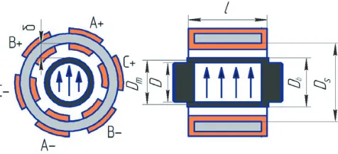
Physical model of this MEEC has been developed to study the thermal state, (Figure 2) with the geometric dimensions shown in Table 1. The real rotating machine is replaced by a static one, so the winding is placed on the rotor for simulation of eddy currents losses.
Figure 2. Physical model of MEEC. Here: 1 – stainless steel; 2 – magnetic core of the stator; 3 – windings; 4 – a rotor with a nichrome coil wounded on it; 5 – nichrome coil.
As can be seen from Table 1, a large part of the losses (12.51 Watts, 75% of total losses) occurs in the rotor and shaft (losses in bearings, rotor losses on friction of air). The physical model consists of a rotor (permanent magnets on which the winding is wound to simulate eddy-current losses) and a stator (a ferrite rod with a winding). All materials used in the physical model correspond to Table 1.
by the thermal imager. This allows to accept that the reflection coefficient of thermal imager equal to 0.87.
Figure 3 shows the stand for experimental studies.
Figure 3. The stand for experimental research. Here: 1 — thermal imager; 2 — physical model; 3 — measuring system; 4 — current source.
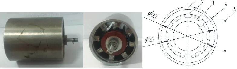
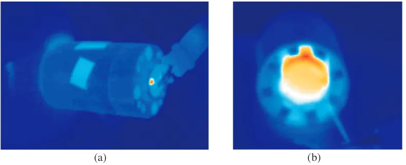
Figure 4(a) shows the spectrum of heat generation in MEEC obtained with thermal imager in the tenth minute measurement. Figure 4(b) shows the spectrum when removing the bearing shield. Figure 5 shows the temperature dependence of the physical model of MEEC on the outer surface of the housing of microgenerator in time, represented by the dynamic curve of MEEC heating.
(a) (b)
Figure 4. The range of heat generation obtained with thermal imager. (a) On the outer surface of the housing; (b) Inside MEEC when removing the bearing shield.
As a result of the experimental studies, it is found that the value of losses is 15 watts; maximum temperature of MEEC housing is not more than 65◦C; the temperature of the rotor and HCPM reaches 150–155◦C; the temperature of stator magnetic core is 80–85◦C.
There are no imposed losses on the stator, so the predicted value of heat release of the magnetic core of a stator is no more than 100–110◦C (taking into account losses and their low value).
Figure 5. Dependence of the housing surface temperature of MEEC on the heating time.
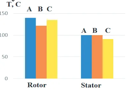
Figure 6. Comparison of the physical analogies method (A), experimental temperature studies given in [5] (B) and mathematical modeling (C).
It can be seen from Figure 6 that the proposed mathematical description and the method of physical analogies show small discrepancies from the results of the experiments given in [5]. The discrepancy is not more than 10% which is a good result. It should be noted that both methods used allow to study dynamic thermal processes.
Thus, dynamic indices of its heating and the temperature of the active parts were identified in the experimental studies.
The study of the influence of temperature on the characteristics of HCPM (residual flux density and coercive force), electric steels and magnetic alloys are presented in various papers [17]. At the same time, there are no publications describing experimental studies of the magnetic flux density changes in the air gap of electromechanical energy converters with HCPM when the HCPM are heated. Also there is no analysis of the impact of this change on the efficiency of MEEC. A similar situation occurs in studies of changes in the specific losses in amorphous steel when the temperature changes. All of the studies presented in the publication are related to electrical steel or soft magnetic materials at frequencies of 50 and 400 Hz, and there are no studies of specific losses changes in amorphous steels at high frequency magnetization reversal. It also does not show the heating effect on the rotor friction losses of air in the air gap. It is a very important issue for slotless MEEC where this type of losses can reach up to 15–20% of the total volume of losses.
3.2. Experimental Studies of the Effect of the Temperature of the Stator Magnetic Core on the Efficiency of the MEEC
of Electromechanics of USATU.
Experimental studies were carried out according to the measurements procedure laid down in the instruction manual 4276.020.20872624.2009 [18]. Measurements of specific losses were made in normal climatic conditions at the temperature of the samples not more than 23◦C at the relative humidity of 25% and at a temperature not exceeding 70◦C (for research at a temperature of not more than 70◦C sample was subjected to heating in a muffle furnace). After the studies of a sample in a hot condition, measurements in the cold state at a temperature not exceeding 23◦C were carried out. Measurement of the mass of the samples was carried out on an electronic scale with accuracy less than 0.01 grams.
In this installation, measurements of the specific losses were made at different temperatures in the ring samples of amorphous steel of two different types (type E and T of 5BDSR brand production of Asha Metallurgical Plant [19], the saturation flux density of 1.3 T).
As a result of experimental studies, it was found that when the temperature of stator magnetic core made from amorphous steel 5BSDR type T (linear hysteresis loop) was increased by 50◦C, specific losses in the stator magnetic core were reduced by 15%. When the temperature of the stator magnetic core made from amorphous steel 5BSDR type E (rectangular hysteresis loop) was increased by 50◦C, specific losses in the stator magnetic core were reduced by 14%.
Thus, the experimental results show that with the increase of the temperature of the stator magnetic core made from amorphous steel, specific losses are reduced by 15%. These results may have a special value not only for the design of the MEEC with magnetic core made from amorphous steel but particularly for the magnetic cores of transformers, wherein the amorphous steel is widely used.
Losses in the magnetic core of MEEC in operation will also be reduced due to lower energy characteristics of HCPM and thus decrease the flux density in the magnetic core. The magnitude of this reduction will be assessed after the experimental studies of the effect of temperature on the HCPM on magnetic flux density in the air gap of MEEC.
3.3. Experimental Studies of the Effect of Temperature on Energy Characteristics of the HCPM and Efficiency of MEEC
An experimental installation was developed to study the changes of the flux density in the air gap and to analyze the effect of changes on the efficiency of MEEC. Experimental installation comprises a magnetic system made of steel laminated with 3411 sheets of 0.35 mm thick. Non-magnetic lining is arranged on the surface of the magnetic system to monitor the air gap (air gap of 4 mm between the HCPM and the pole of the magnetic system). Heating of the HCPM was made by two electric heaters. One electric heater directly heats the HCPM, and the other heats magnetic system. The magnetic flux density in the air gap is measured by the Hall sensor (temperature coefficient of the Hall sensor is 0.02%/K) connected to milliteslameter TPU-05. Temperature measurement is carried out using a thermocouple connected to multimeter.
As the sample in experimental studies HCPM Sm2Co17 by rectangular shape (30×20×10) was
used with the initial characteristics: Br = 1.08 T, the coercive force by flux density Hb = 692 kA/m, and the maximum operating temperature is 350◦C. This type of HCPM was chosen because exactly this type was used in MEEC designed by Onera (Table 1).
As a result of experimental studies, the values of the magnetic flux density in the air gap of the experimental installation (Bδ) for different temperatures of HCPM (HCPM) based on alloy Sm2Co17
were determined which by interpolation were transformed into the dependence.
As a result of convective heating of HCPM based on the Sm2Co17 alloy it was found that with
the increase in temperature from 80 to 120◦C the flux density in the air gap of the experimental setup decreased linearly from 0.471 to 0.455 T (by 3.3% or 0.85% by 10◦C). With an increase in temperature from 120 to 150◦C (the value of the temperature of the HCPM obtained during the experimental studies of the thermal state of the MEEC) the flux density decreased sharply from 0.455 to 0.438 T (by 3.8% or 1.3% by 10◦C) along a curve close to the exponential curve.
In the subsequent cycles of cooling-heating of HCPM based on the Sm2Co17 alloy the curves
of MEEC with the parameters of Table 1, the magnetic flux density in the air gap of MEEC decreases by 6%. Constancy input of mechanical power and the constancy of electric power consumption will increase the linear current load of MEEC and accordingly increase the current value by 6% too. Given that the resistance of copper at a temperature of 100–110◦C is also increased by 38%, the ohmic losses in the stator winding increase 1.55 times.
Idealized linear relation of current and the magnetic flux density in the air gap of MEEC was adopted when evaluating the change of the linear current load and the magnetic flux density. In a real MEEC, the increase of the linear current load will lead to an increase of demagnetization action of armature reaction and additional heating of the winding and consequently will lead to increased resistance. Preliminary calculations including all the described processes showed that the losses in the winding of real MEEC in a cold state and 10 minutes after the start of operation may vary 1.6–1.65 times.
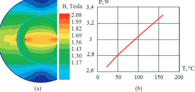
The change of magnetic flux density in the air gap will not only increase the current but also reduce the magnetic flux density in the magnetic core of stator which also will reduce the losses in the stator magnetic core. To estimate this reduction, a computer model with geometrical dimensions presented in Table 1 was developed in the software package Ansoft Maxwell, and a computer modeling of the magnetic field distribution on the cross section of the stator magnetic core of MEEC was made. Figure 7 shows the simulation results for the cold MEEC (at 23◦C).
(a) (b)
Figure 7. The results of the (a) MEEC modeling in the cold state and (b) dependence of air friction losses of the rotor from the air temperature.
The heating of HCPM until 150◦C leads to the decrease of magnetic flux density in the stator magnetic core by 6–6.5%. Taking into account the dependence of specific losses on amorphous alloys by flux density then further heating leads to a reduction of losses in the stator magnetic core by 13–15%.
Thus, heating of the HCPM during operation in MEEC with the parameters according to Table 1 increases the current in the windings due to the increase of the linear current load. Since increase of resistance in the windings increases losses in MEEC 1.6–1.65 times, the losses in the stator magnetic core are reduced 1.13–1.15 times by reducing the magnetic flux density in it. The total losses in the stator magnetic core (including the increase of the temperature) will be 1.3 times less than in the cold state.
4. EFFECT OF INCREASE OF THE AIR TEMPERATURE ON THE EFFICIENCY OF MEEC
In addition to the properties changes of the active materials of MEEC by heat, there is also a change of air properties inside MEEC (decreased density and kinematic viscosity increases). This will undoubtedly lead to a change of friction losses in the rotor around the air.
Known models of aerodynamic losses do not take this into account, but any change in losses can affect the efficiency when it comes to MEEC with low power.
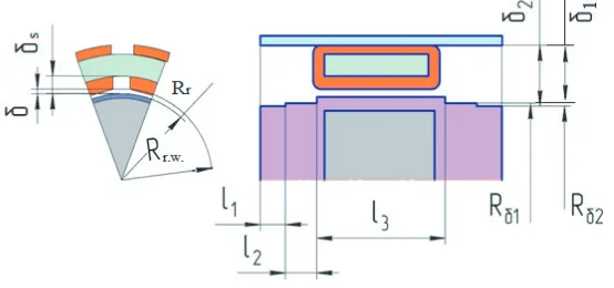
Therefore, it is necessary to make corrections into the known model of aerodynamic losses [6]. The calculation scheme for making corrections is shown in Figure 8.
Figure 8. Calculation of aerodynamic losses in MEEC considering the temperature.
It is known that the magnitude of the friction coefficient of the rotor with air is determined by the Reynolds and Taylor numbers:
Re= R
2
rΩ
ς , Ta= RrΩδ
ς
δ
Rr, cf =
1.8 Re
δ Rr
−0.25 R2 r.w.
R2
r.w.−R2r
(5)
where ς — kinematic viscosity of air; Rr.w. — radius to winding; δ — air gap of MEEC; Ω — rotor
speed; Rr — radius of the rotor with the shroud.
The coefficient of friction of the rotor with an air gap for the zone without winding is adopted in the form:
f1 = 1.8
Re
δ+δs
Rr
−0.25 R2 r.w.
[Rr.w.+δs]2−R2r
(6)
whereδs — distance in a zone not occupied by a winding.
The Reynolds number can be rewritten in a general form taking into account the fact that the kinematic viscosity of air depends on its temperature:
Re= R
2
iΩ
ς(T, pa), (7)
where ς(T, pa) — kinematic viscosity of air at a certain temperature and pressure; Ri — radius of rotating part of rotor or shaft;pa — air gap pressure.
Then taking into account the fact that the air density also depends on the temperature, the aerodynamic losses of the rotor for the slot zone are determined in the form:
Pa.l.sl.=
1.8 Re(Rr)
δ+δs
Rr
−0.25
[Rr.w.+δs]2
[Rr.w.+δs]2−R2r
ρair(T, pa)Ω3R3rl3zbw
2 , (8)
wherel3 — active part length;bw — the width of the zone occupied by the winding.
And for the stator zone with winding:
Pa.l.st.w.=
1.8 Re(Rr)
δ Rr
−0.25 R2 r.w.
R2
r.w.−R2r
ρair(T, pa)Ω3Rr3l3zbz
where z — number of stator windings; bz — band width without winding; ρair(T) — air density at a
certain temperature.
Provided that the air temperature is the same over the entire surface of the air gap, the total aerodynamic losses of the shaft with the rotor according to the calculation scheme are defined as:
Pa.l.sh.r. =
1.8 Re(Rr)
δ Rr
−0.25 R2 r.w.
R2
r.w.−R2p
ρair(T, pa)Ω3R3rl3zbz
2
+ 1.8 Re(Rr)
δ+δs
Rr
−0.25 [R
r.w.+δs]2
[Rr.w.+δs]2−R2r
ρair(T, pa)Ω3R3rl3zbs
2
+ 3.6 Re(Rδ1)
δ1
Rδ1
−0.25
(Rδ1+δ1)2
2Rδ1δ21+δ21
ρair(T, pa)Ω3R4δ1l2
+ 3.6 Re(Rδ2)
δ2
Rδ2
−0.25
(Rδ2+δ2)2
2Rδ2δ22+δ22
ρair(T, pa)Ω3R4δ2l1, (10)
where l1, l2 — lengths of the first and second shaft stages, respectively; Rδ1, Rδ2 — radii of the first
and second shaft stages, respectively; δ1,δ2 — distances from the first and second stages of the shaft
to the housing, respectively.
Calculations were made for four temperatures (23◦C 50◦C, 100◦C, 160◦C), and the kinematic viscosity of the air and its density were taken into account in the calculations. The results of the calculations are shown in Figure 7.
It can be seen from Figure 7 that with increasing temperature the rotor’s losses due to friction against air increase (when the temperature is increased 5 times from 23◦C to 100◦C, the losses increase 1.15 times).
5. RESULTS AND CONCLUSION
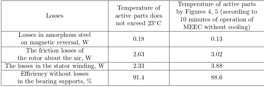
To sum up the studies will be useful to make comparisons of losses and efficiency of MEEC in a cold state and after 10 minutes of operation without cooling. The results of this comparison are shown in Table 2 (the change of losses in the bearing supports under the influence of temperature is not taken into the account).
Table 2. Results of the comparison of losses of MEEC in a cold state and 10 minutes after the operation.
Losses
Temperature of active parts does
not exceed 23◦C
Temperature of active parts by Figures 4, 5 (according to
10 minutes of operation of MEEC without cooling) Losses in amorphous steel
on magnetic reversal, W 0.18 0.13
The friction losses of
the rotor about the air, W 2.63 3.02
The losses in the stator winding, W 2.33 3.88
Efficiency without losses
in the bearing supports, % 91.4 88.6
by 6–6.5%, and this (taking into account depending of specific losses for amorphous alloys from flux density) will reduce further losses in the stator magnetic core by 13%–15%.
Thus, the heating of the permanent magnets (during operation of MEEC) increases the current in the windings by increasing the linear load current while (also taking into account the increase in the resistance) losses in the windings increased by 1.6–1.65 times, and losses in the stator magnetic core (by decreasing the flux density in the magnetic core) decreased by 1.13–1.15 times. A complete reduction in losses in the stator magnetic core (including the increase of its temperature) will be 1.36 times (compared with the cold state).
Moreover, a mathematical apparatus for the analysis of dynamic thermal processes in MEEC with high accuracy was obtained.
Based on the obtained results, it is possible to accurately predict the thermal state of the MEEC in various moments of its operation which allows estimation of the power produced by the MEEC. In particular, we have definitely determined the exact operating time of a microgenerator without a cooling system for a UAV power supply system using the proposed method. The running time was 10 minutes. It has also defined a change in the produced power. This provided an opportunity for developers of a UAV to select the optimal fuel reserves to be used on board. Moreover, this allows calculation of the optimum trajectory of the apparatus. Optimal modes of power consumption on UAV were selected on the basis of our research.
It would be helpful to consider the further degradation. After 20 minutes of operation (due to the heating of permanent magnets and the deterioration of energy properties), the power of the machine will be reduced by 2 times. 30 minutes of operation will melt the insulation.
ACKNOWLEDGMENT
The work was supported by the Russian Science Foundation, project 17-79-20027.
REFERENCES
1. Ismagilov, F. R., V. E. Vavilov, I. I. Yamalov, and V. V. Ayguzina, “Transients in ultra-high-speed generators of micro-sized gas turbines,”Progress In Electromagnetics Research M, Vol. 59, 123–133, 2017.
2. Zwyssig, C., J. W. Kolar, and S. D. Round, “Mega-speed drive systems: Pushing beyond 1 million RPM,”IEEE/ASME Transactions on Mechatronics, Vol. 14, No. 5, 564–574, 2009.
3. Zwyssig, C., S. D. Round, and J. W. Kolar, “An ultrahigh-speed, low power electrical drive system,”
IEEE Transactions on Industrial Electronics, Vol. 55, No. 2, 577–585, 2008.
4. Zwyssig, C., J. W. Kolar, W. Thaler, and M. Vohrer, “Design of a 100 W, 500000 rpm permanent-magnet generator for mesoscale gas turbines,” Proceedings of IEEE Industry Applications Conference 2005, Conference Record of the 40th IAS Annual Meeting, Vol. 1, 253–260, Hong Kong, Oct. 2–6, 2005.
5. Zwyssig, C., S. D. Round, and J. W. Kolar, “Power electronics interface for a 100 W, 500000 rpm gas turbine portable power unit,” Proceedings of Applied Power Electronics Conference, 283–289, Dallas, Texas, USA, Mar. 19–23, 2006.
6. T¨uys¨uz, A., M. Steichen, C. Zwyssig, and J. W. Kolar, “Advanced cooling concepts for ultra-high-speed machines,”9th International Conference on Power Electronics and ECCE Asia (ICPE-ECCE Asia), 2194–2202, 2015.
7. Isomura, K., M. Murayama, S. Teramoto, K. Hikichi, Y. Endo, S. Togo, and S. Tanaka, “Experimental verification of the feasibility of a 100 W class micro-scale gas turbine at impeller diameter 10 mm,” Proceedings of the Fifth International Workshop on Micro and Nanotechnology for Power Generation and Energy Conversion Applications, 254–261, Tokyo, Japan, Nov. 28–30, 2005.
Nanotechnology for Power Generation and Energy Conversion Applications (Power MEMS), 1–4, Daejeon, 2011.
9. Beyaz, M. I., B. M. Hanrahan, J. Feldman, and R. Ghodssi, “An integrated permanent-magnet microturbogenerator supported on microball bearings,”Journal of Microelectromechanical Systems, Vol. 22, No. 3, 2013.
10. Saban, D. M., C. Bailey, D. Gonzalez-Lopez, and L. Luca, “Experimental evaluation of a high-speed permanent-magnet machine,” Petroleum and Chemical Industry Technical Conference, 2008. 11. Uzhegov, N., E. Kurvinen, J. Nerg, J. T. Sopanen, and S. Shirinskii, “Multidisciplinary design
process of a 6-slot 2-pole high-speed permanent-magnet synchronous machine,”IEEE Transactions on Industrial Electronics, Vol. 63, No. 2, 174–178, 2016.
12. Huynh, C., L. Zheng, and D. Acharya, “Losses in high speed permanent magnet machines used in microturbine applications,” J. of Engineering for Gas Turbines and Power, Vol. 131, No. 2, 1–6, 2009.
13. Dorrell, D., “Combined thermal and electromagnetic analysis of permanent-magnet and induction machines to aid calculation,” IEEE Transactions on Industrial Electronics, Vol. 55, No. 10, 3566– 3574, 2008.
14. Vong, P. and D. Rodger, “Coupled electromagnetic-thermal modeling of electrical machines,”IEEE Trans. on Magn., Vol. 39, No. 3, 1614–1617, 2003.
15. Ismagilov, F., V. Vavilov, I. Hairullin, and D. Gusakov, “High efficiency ultra-high speed microgenerator,” Proceedings of IECON 2016 — 42nd Annual Conference of the IEEE Industrial Electronics Society, 1670–1674, 2016.
16. Ismagilov, F., V. Vavilov, V. Aiguzina, and V. Bekuzin, “Minimization of energy losses in ultra-high-speed electrical rotating machines,” ElektrotehniˇsKi Vestnik, Vol. 84, No. 1–2, 56–60, 2017. 17. JSC, ”Scientific and production association “INTROTEST” electronic source,” Link:
http://www.-introtest.com/ (date of the application 16.08.2017).
18. Electronic source, Available: http://www.introtest.com/usr/06/MK4E/MK4E magnitoprovod.pdf (date of application 24.09.17).