A Compact Multiband Planar Monopole Antenna for Slim Mobile
Handset Applications
Pradutt Kumar Bharti, Gaurav Kumar Pandey, Hari Shankar Singh, and Manoj Kumar Meshram*
Abstract—A planar compact multiband monopole antenna is presented for ultra-slim mobile handset applications. The proposed antenna operates over 0.885 GHz–0.962 GHz and 1.69 GHz–3.8 GHz frequency bands with−6 dB impedance bandwidth that covers GSM900, GSM1800, GSM1900, UMTS, IMT2100, WLAN, WiMAX along with most of the higher LTE bands of modern mobile phone applications. The radiation characteristics of the antenna is analyzed in term of radiation patterns, peak realized gain, total radiation efficiency, and surface current distribution. The radiation patterns of the proposed antenna are dipole like which is suitable for mobile applications with 73–93% total radiation efficiency. The proposed antenna is investigated in free space as well as in actual mobile environment consisting of mobile plastic housing along with large metallic display screen and battery. No significant effect on the operating bands of the mobile antenna due to the actual mobile environment on the impedance bandwidth is observed. Specific absorption rate (SAR) computation is carried out on human head phantom. The computed values of SAR lie well below the specified limit over 1 g and 10 g of tissues. The parametric analysis is also carried out to understand the effect of the shape parameters.
1. INTRODUCTION
With the rapid growth in the mobile handset technology for communication systems there is always demand for compact thin profile antennas with multiband as well as broadband functionality so that it can be easily accommodated in the ultra-slim mobile handsets. The multiband antennas can operate over different frequency bands used for increasing number of applications for modern handsets which include real time speech communication, text message service, internet surfing, global positioning system (GPS), games, audio and video applications, etc. Therefore, use of multiband and broadband antennas can minimize the problem of placing multiple antennas for different applications.
Design of simple, compact, and low cost multiband antennas for mobile phone applications, which can be easily accommodated with mobile handset circuitry without affecting the other performances of antenna, is a great challenge to antenna designers. Limitation of size in mobile handsets makes it difficult to design antenna with good impedance matching and radiation performances over a number of operating bands which leads to the antennas with narrow bandwidth and low return loss level. Therefore, mobile handset antennas are designed to have a minimum reflection coefficient value of −6 dB in the operating bands, which is generally low compared to other applications [1].
Keeping pace with the rapid development of modern mobile communication, several multiband antennas for mobile handset applications have been reported, such as inverted-F antennas (IFA) [2–4], planar inverted-F antennas (PIFA) [5–9], folded chip antennas [10–12], and monopole antennas [13– 24]. Although PIFA and IFA are compact antennas with quarter wavelength structures, suitable for
Received 27 June 2014, Accepted 14 August 2014, Scheduled 9 September 2014 * Corresponding author: Manoj Kumar Meshram ([email protected]).
conventional mobile handsets, they have some inherent disadvantages. For example, these antennas are designed on some height in addition to substrate, and they consist of shorting plate/pin which adds to antenna design complexity. Folded chip antennas also have some design complexities. For example, they generally employ two layers of radiating structures, and the layers are generally connected through shorting pins or other structures. Therefore, planar monopole antennas are suitable for ultra-slim mobile phones and have compact quarter wavelength resonating structure with planar geometry which can be easily etched during the fabrication of printed circuit board (PCB) of mobile phones.
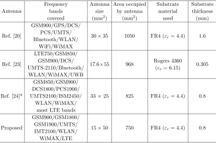
Although several monopole antennas have been reported in literature, they have some demerits that make them unsuitable for modern handsets with lot of applications. In [13, 19], simple planar multiband monopole antennas are proposed, which cover all the frequency bands that can be utilized for the conventional mobile phone but they do not cover either WLAN or WiMAX bands which are very important in modern day handsets. Similarly, in [14, 18, 22], monopole antennas for mobile handsets have been proposed but these antennas do not operate over any of the communication bands below 1 GHz which is also a great disadvantage for recent applications, whereas antenna proposed in [15] does not have planar structure. The monopole antennas proposed in [16, 17] do not operate over WiMAX frequency band. While [20, 23, 24] cover almost all the frequency bands with planar and simple structure, they have limitation in terms of the area occupied by the antenna structure on the mobile circuit board. In this paper, a compact, multiband, uniplanar monopole antenna which covers GSM900/GSM1800/ GSM1900/UMTS/IMT2100/WLAN/LTE2500/WiMAX frequency bands along with all the higher LTE (Long Term Evolution) frequency bands is proposed. The comparison of the proposed antenna with the existing antennas [20, 23, 24] is given in Table 1. The proposed antenna is investigated in free space as well as in mobile environment. SAR calculation is also carried out on SAM (Specific Anthropomorphic Mannequin) head phantom. The details of antenna design concepts and characterization results along with detail discussions are presented in following sections.
Table 1. Comparison of proposed antenna with reference antennas.
Antenna
Frequency bands covered
Antenna size (mm2)
Area occupied by antenna
(mm2)
Substrate material
used
Substrate thickness
(mm)
Ref. [20]
GSM900/GPS/DCS/ PCS/UMTS/ Bluetooth/WLAN/
WiFi/WiMAX
30×35 1050 FR4 (εr= 4.4) 1.6
Ref. [23]
LTE750/GSM850/ GSM900/DCS/ UMTS-2110/Bluetooth/
WLAN/WiMAX/UWB
17.6×55 968 Rogers 4360 (εr= 6.15)
0.305
Ref. [24]*
GSM850/GSM900/ DCS1800/PCS1900/ UMTS2100/ISM2450/
WLAN/WiMAX/ most LTE bands
33 ×25 825 FR4 (εr= 4.4) 0.8
Proposed
GSM900/GSM1800/ GSM1900/UMTS/ IMT2100/WLAN/
WiMAX/LTE
15×50 750 FR4 (εr= 4.4) 0.8
2. ANTENNA CONFIGURATION
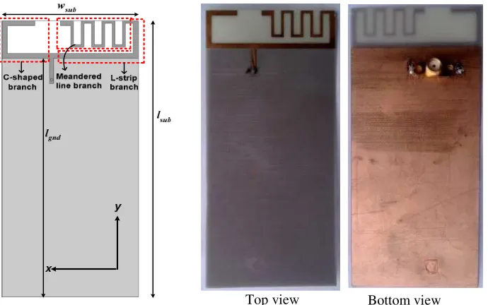
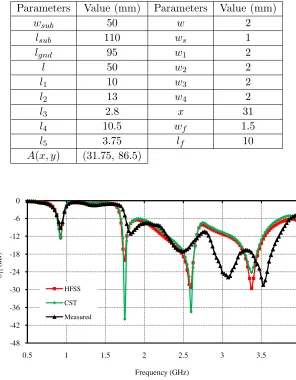
Figure 1 shows the configuration of the proposed antenna with fabricated prototype for the ultra-slim mobile handset applications. This antenna consists of two resonating branches (a C-shaped and a meandered line connected with L-strip), 50 Ω microstrip line, and a mobile circuit board. The mobile circuit board is made of a FR4 substrate with dielectric constant 4.4 and loss tangent 0.018. The dimension of the circuit board is chosen as 50×110 mm2 with height (h) of the substrate 0.8 mm. Figure 2 shows the details of the proposed antenna which is printed on the no ground portion of size 15×50 mm2 on one side of the circuit board which is fed by 50 Ω microstrip line, printed on the same side of the antenna whereas the ground plane of size 50×95 mm2 is printed on the opposite side of the antenna. The electrical length of the meandered line branch is approximated as 3λ/8 at the lowest resonant frequency [25]. C-shaped branch is responsible for the higher frequency bands. The electrical length of the C-shaped branch can be approximated as λ/4 at lower edge operating frequency of the higher frequency band. The shape parameters of the antenna are optimized using FEM (Finite Element Method) based Ansoft’s HFSS [26], to achieve the GSM900 (0.885 GHz–0.962 GHz) and higher LTE bands along with GSM, UMTS, IMT 2000, WLAN, and WiMAX bands (1.69 GHz–3.8 GHz). GSM900 and 1.69 GHz–3.8 GHz are referred as lower and higher frequency bands in the manuscript, respectively. The optimized shape parameters of proposed antenna are shown in Table 2.
Top view Bottom view
Figure 1. The configuration of the proposed antenna with fabricated prototype.
3. ANTENNA CHARACTERIZATION IN FREE SPACE
Figure 2. Detail dimensions of the proposed antenna.
Table 2. Optimized shape parameters of the proposed antenna.
Parameters Value (mm) Parameters Value (mm)
wsub 50 w 2
lsub 110 ws 1
lgnd 95 w1 2
l 50 w2 2
l1 10 w3 2
l2 13 w4 2
l3 2.8 x 31
l4 10.5 wf 1.5
l5 3.75 lf 10
A(x, y) (31.75, 86.5)
-48 -42 -36 -30 -24 -18 -12 -6 0
0.5 1 1.5 2 2.5 3 3.5 4
S11
(dB)
Frequency (GHz)
HFSS
CST
Measured
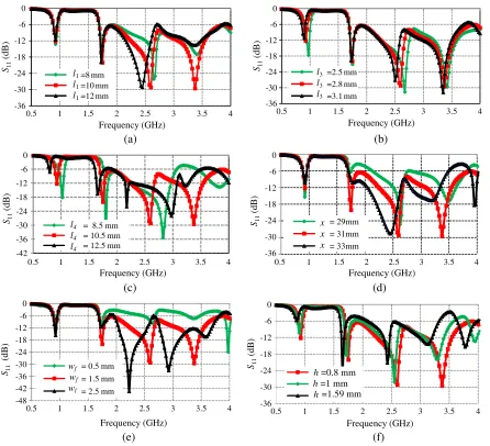
3.1. Parametric Analysis
Parametric study of some critical dimensions/shapes of the antenna is carried out to analyze the effect of the shape parameters on the operating frequency bands using HFSS. The antenna is designed to cover the GSM900 (0.885 GHz–0.962 GHz) and higher LTE bands along with GSM, UMTS, IMT 2000, WLAN, and WiMAX bands (1.69 GHz–3.8 GHz).
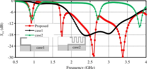
Since the proposed antenna comprises two resonating branches, it is interesting to see the effect of individual branch on the impedance bandwidth of the antenna. When both the branches are considered separately on the same circuit board, the meandered line strip connected with L-shaped strip (case 2) has fundamental (3/8) λresonating mode near 0.94 GHz with other higher order modes resonating at 2.7 GHz and 3.8 GHz, while the quarter wavelength C-shaped strip (case 1) resonates over wide frequency band from 1.9 GHz to 3.825 GHz. When both the branches are combined to form the proposed antenna, then due to coupling between both the branches result in shift of resonance frequencies towards lower frequency side, and the impedance bandwidth covers most of the frequency bands used in modern mobile handset applications, which is depicted in Figure 4.
-30 -24 -18 -12 -6 0
0.5 1 1.5 2 2.5 3 3.5 4
S11
(dB)
Frequency (GHz)
Proposed case1 case2
case1 case2
Figure 4. The variation of the reflection coefficient with frequency for different configurations.
The effect of variation ofl1 on impedance bandwidth is shown in Figure 5(a). It is observed that with the increase of the length l1, resonant frequency around 2.5 GHz decreases rapidly whereas it is almost unaffected around 3.5 GHz and 1.8 GHz. Also slight increase on the lower edge frequency of the higher frequency band is observed. The impedance bandwidth (S11≤ −6 dB) of higher frequency does not get affected significantly, but the impedance matching around 3 GHz and 2.7 GHz reduces while impedance matching around 2 GHz gets improved. Since the length of quarter wavelength C-shaped strip is responsible for resonating mode around 2.4 GHz and 3 GHz, shifting of resonant frequency around 2.5 GHz towards lower frequency takes place while mismatch occurs around 3.4 GHz.
The effect of variation of lengthl3 is shown in Figure 5(b). It is observed that with the increase of length l3, the resonant frequency around GSM 900, 2.5 GHz, and 3.5 GHz decreases while the resonant frequency around 1.8 GHz is unaffected. This 1.8 GHz resonant frequency is fundamental resonating mode atλ/4 length of C-shaped strip, hence it is unaffected due to change in the length of meandered section. Similar behavior is observed with the variation of length l5 since it directly affects the total length of the branch.
Further, the effect of variation of the length l4 is investigated which is shown in Figure 5(c). It is observed that with the increase of length l4 the effective electrical length of meandered line section increases, and the gap between the meandered line sections with L-strip line decreases which results in shifting of the resonant modes towards lower frequency side while improvement in impedance matching is observed at higher frequency side. The effect of variation of the feed positionxis shown in Figure 5(d). It is observed that the position of the feed affects the impedance matching significantly, specially at the higher frequency side with less effect on the lower frequency bands. The optimized value for the feed position is considered as 31 mm.
(a) (b) (c) (d) (e) (f) -42 -36 -30 -24 -18 -12 -6 0
0.5 1 1.5 2 2.5 3 3.5 4
S11
(dB)
Frequency (GHz)
= 8.5 mm = 10.5 mm = 12.5 mm
-36 -30 -24 -18 -12 -6 0
0.5 1 1.5 2 2.5 3 3.5 4
S11 (dB) Frequency (GHz) = 29mm = 31mm = 33mm -48 -42 -36 -30 -24 -18 -12 -6 0
0.5 1 1.5 2 2.5 3 3.5 4
S11
(dB)
Frequency (GHz)
= 0.5 mm = 1.5 mm = 2.5 mm
-36 -30 -24 -18 -12 -6 0
0.5 1 1.5 2 2.5 3 3.5 4
S11 (dB) Frequency (GHz) l4 l4 l4 x x x wf wf wf
h =0.8 mm
h =1 mm
h=1.59 mm
-36 -30 -24 -18 -12 -6 0
0.5 1 1.5 2 2.5 3 3.5 4
S11 (d B) Frequency (GHz) =8 mm =10 mm =12 mm -36 -30 -24 -18 -12 -6 0
0.5 1 1.5 2 2.5 3 3.5 4
S11 (d B) Frequency (GHz) =2.5 mm =2.8 mm =3.1 mm l1 l1 l1 l3 l3 l3
Figure 5. Variation of reflection coefficient with frequency for (a) l1,(b) l3, (c) l4, (d) x, (e) wf, and
(f)h.
are shown in Figures 5(e) and (f), respectively. It is observed that the variation of feed line width has significant effect on impedance bandwidth towards higher frequency side while less significant effect at lower frequency side, whereas the variation of height of the substrate significantly affect the overall impedance bandwidth. It is observed that with the increase of h all the resonance frequency points are shifted towards the lower frequency side with some impedance mismatch with respect to −6 dB impedance bandwidth.
The effects of variations of ws,w2,w4,and w on impedance bandwidth are shown in Figures 6(a),
(b), (c), and (d), respectively. It is observed that with the increase of ws, the lower frequency band
is not affected significantly while the resonant frequencies of the higher frequency band increases with some impedance mismatching around 3.0 GHz frequency. It is interestingly noted that the impedance matching is improved after 3.5 GHz with the increase of ws. It is worth mentioning that during the
simulation process we observe that the value of width w1 does not significantly influence the reflection coefficient as well as the impedance bandwidth of the antenna. Also, it is observed that the reflection coefficient and impedance bandwidth remain almost unaffected by the variation of the widthw3.
(a) (b) (c) (d) -42 -36 -30 -24 -18 -12 -6 0
0.5 1 1.5 2 2.5 3 3.5 4
S11 (d B) Frequency (GHz) =0.5mm =1mm =1.5mm -48 -42 -36 -30 -24 -18 -12 -6 0
0.5 1 1.5 2 2.5 3 3.5 4
S11 (d B) Frequency (GHz) = 1mm = 2mm = 3mm -4 2 -3 6 -3 0 -2 4 -1 8 -1 2 - 6 0
0.5 1 1.5 2 2.5 3 3.5 4
S11 (d B) Frequency (GHz) = 1mm = 2mm = 3mm -36 -30 -24 -18 -12 -6 0
0.5 1 1.5 2 2.5 3 3.5 4
S11
(d
B)
Frequency (GHz) = 1 mm
= 2 mm = 3 mm
w2 w2 w2 ws ws ws w4 w4 w4 w w w
Figure 6. Variation of reflection coefficient with frequency for different width (a) ws, (b) w2, (c) w4, and (d)w.
(a) 0.925 GHz (b) 1.925 GHz
(c) 2.45 GHz (d) 3.5 GHz
Figure 7. The surface current distributions of proposed antenna at different frequencies.
3.2. Current Distributions and Far Field Radiation Patterns
To understand the radiation mechanism of the proposed antenna, the simulated surface current distributions on the proposed antenna at different frequencies (0.925 GHz, 1.925 GHz, 2.45 GHz, and 3.5 GHz) are presented in Figure 7. At 0.925 GHz, the relatively strong current distributions are seen on the meandered line and L-strip sections, which indicates that dominant mode is excited, and lower resonant mode at about 0.925 GHz is mainly contributed by these sections. It is also observed from Figures 7(b), (c), and (d) that there are strong surface current distributions on the meandered line, L-strip, and C-shaped strip sections, which suggests that resonant modes at 1.925 GHz, 2.45 GHz, and 3.5 GHz frequencies are provided by all these sections.
The radiation characteristics of the proposed antenna in three principal planes are shown in Figure 8. It is observed that the Eθ-component makes dumbbell-like shape in XY- and Y Z-planes
and is close to omnidirectional pattern inXZ-plane for all the resonant frequencies. It is interestingly noted that at 0.925 GHz and 2.45 GHz in Figures 8(a) and 8(c) respectively, the Eθ-component of the
field is dominant and provides smooth variations over all the θangles which can be seen in XZ-plane. This is because the dominant mode is excited at 0.925 GHz and favorable higher order mode excited at 2.45 GHz, which can be seen from the current distributions on aperture as shown in Figures 7(a) and 7(c),
X-Y Plane (Theta = 90 and Phi = all)
Eθ (vertical component) Eϕ (horizontal component)
(i) (j) (k) (l)
X-Z Plane(Theta = all and Phi =0)
Y-Z Plane(Theta =all and Phi =90)
(a) (b) (c) (d)
(e) (f) (g) (h)
0 10 20 30 40 50 60 70 80 90 100
0 0.5 1 1.5 2 2.5 3 3.5 4 4.5 5
0.7 1.2 1.7 2.2 2.7 3.2 3.7
T
o
ta
l Rad
iat
io
n
E
ff
ici
en
cy
(%)
P
eak Real
iz
ed
G
ai
n
(d
Bi
)
Frequency (GHz)
Total Radiation Efficiency Peak Realized Gain
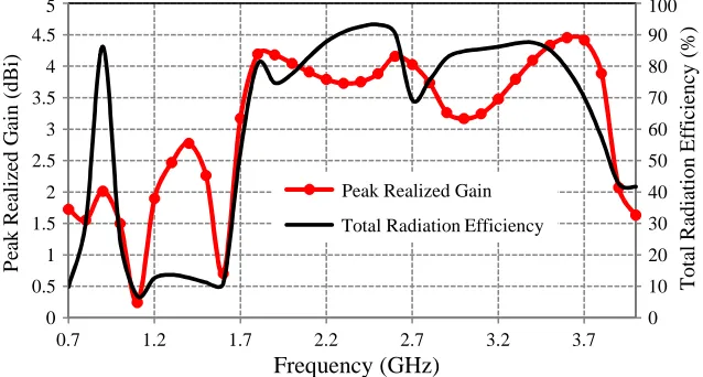
Figure 9. The variation of peak realized gain and total radiation efficiency with frequency.
respectively. However, at 1.925 GHz and 3.5 GHz in Figures 8(b) and 8 (d) respectively, Eθ-component
of field does not vary uniformly over all theθangles, and two nulls can be seen in both the frequencies at θangles of 30 and 150 degrees and at 210 and 330 degrees, respectively, which are due to the generation of unfavorable higher orders modes as indicated from current distributions in Figures 7(b) and 7(d), respectively. InY Z-plane, Eϕ-component of field is dominant and has almost uniform variations over
all ϕ angles. Comparable Eθ and Eϕ components are seen in all the three principal planes resulting
in elliptical polarization. In mobile application, there is a significance of total field rather than one component, so even though the vertical component variation is not uniform, an addition of both the vertical and horizontal components gives fairly good angular coverage. The calculated realized gain and efficiency variation with frequency are shown in Figure 9. The peak realized gain value at lower frequency (0.925 GHz) is found to be 1.4 dBi which is low. As the frequency increases the peak realized gain increases, and maximum value of the gain is found to be 4.5 dBi about 3.7 GHz. The total radiation efficiency of the antenna lies in the range of 73% to 93% in the operating frequency bands which show good radiation characteristics.
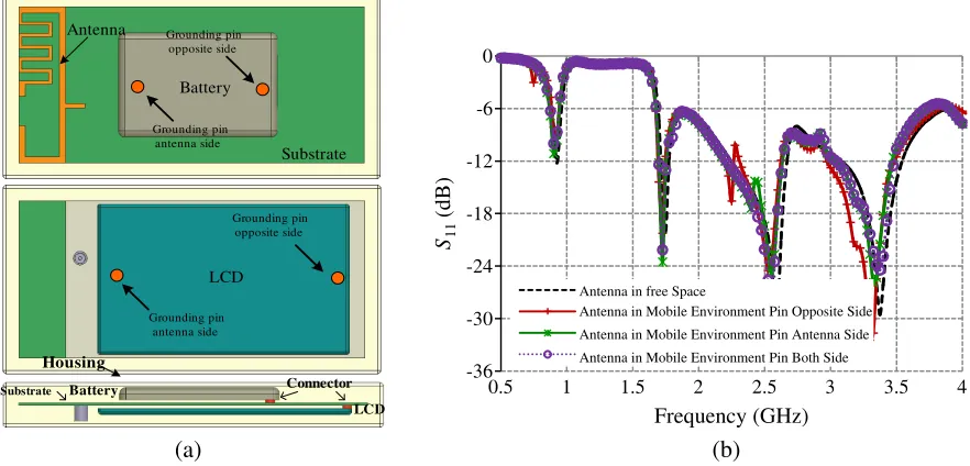
4. ANTENNA CHARACTERIZATION IN MOBILE ENVIRONMENT
5. EFFECT OF THE HUMAN HEAD
The radiation in human body can be evaluated by SAR, which represents the time rate of microwave energy absorbed inside the tissues [29],
SAR = σ
2ρ E2 (1)
where ρ and σ are the density (S/m) and electrical conductivity (Kg/m3) of the tissue, respectively, and E is the internal induced electric field (V/m).
Figure 11 shows the SAR simulation model based on CST MWS and the simulated values for 1 g and 10 g head tissues. The human head phantom model available in CST MWS is considered in this study which consists of two layers namely fluid and shell. Fluid is confined in the shell which is the outer layer. The dielectric properties of the fluid and shell are considered from [28]. The simulated SAR
(b)
-36 -30 -24 -18 -12 -6 0
0.5 1 1.5 2 2.5 3 3.5 4
S11
(dB)
Frequency (GHz)
Antenna in free Space
Antenna in Mobile Environment Pin Opposite Side
Antenna in Mobile Environment Pin Antenna Side
Antenna in Mobile Environment Pin Both Side
Battery
Substrate Antenna
LCD
Battery
LCD Connector Substrate
Housing
Grounding pin opposite side
Grounding pin antenna side
Grounding pin opposite side
Grounding pin antenna side
(a)
Figure 10. (a) Antenna in mobile environment. (b) Effect of mobile environment onS-parameters.
Simulation SAR distributions for 1 g
Simulation SAR distributions for 10 g
0.925 GHz 1.925 GHz 2.45 GHz 3.5 GHz
0.925 GHz 1.925 GHz 2.45 GHz 3.5 GHz
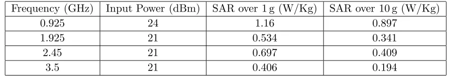
Table 3. SAR values of antenna on SAM head.
Frequency (GHz) Input Power (dBm) SAR over 1 g (W/Kg) SAR over 10 g (W/Kg)
0.925 24 1.16 0.897
1.925 21 0.534 0.341
2.45 21 0.697 0.409
3.5 21 0.406 0.194
values are obtained at four different frequencies. The input power for the SAR calculation is 24 dBm or 0.25 W for the case GSM900 band, and for the rest of the higher frequency band (1.69 GHz–3.8 GHz), the input power is 21 dBm or 0.125 W. The calculated values of SAR over 1 g and 10 g head tissues are given in Table 3. It is observed that the obtained values are well below the specified limit. The results indicate that the proposed antenna is a promising candidate for the modern ultra-slim mobile phones.
6. CONCLUSION
A multiband, compact, low cost, planar monopole antenna covering GSM900, GSM1800, GSM1900, UMTS, IMT2100, WLAN(2.4 GHz), LTE2500, and WiMAX bands along with most of the higher LTE bands is investigated for modern days ultra-slim mobile handsets. Since the antenna has small size with planar geometry without any shorting elements such as shorting pins/plates, it is easy to fabricate with simple photolithography processes and can be fitted easily in ultra-slim mobile phones. The multi-branch monopole structure is proposed, which takes advantage of resonating at different fundamental frequency bands along with higher order modes, and mutual coupling between them leads to achievement of lower operating bands. The effect of mobile environment such as presence of LCD, battery, and plastic housing on antenna impedance bandwidth is found to be less significant. Further, the SAR computation on the human head phantom shows that the value of the SAR is well below the specified limit. The antenna shows good far-field radiation characteristics making it promising for mobile handset applications. The aforementioned attributes make the proposed antenna attractive for portable devices as well as for ultra-slim mobile handsets.
REFERENCES
1. Seko, M. H. and F. S. Correra, “A novel tri-band planar inverted-F antenna for GSM/DCS/PCS operation in mobile handsets,”Microwave Opt. Technol. Lett., Vol. 55, 821–825, 2013.
2. Kuo, Y.-L. and K.-L. Wong, “Coplanar waveguide-fed folded inverted-F antenna for UMTS application,”Microwave Opt. Technol. Lett., Vol. 32, 364–366, 2002.
3. Chiu, C.-W. and Y.-J. Chi, “Planar hexa-band inverted-F antenna for portable device applications,” IEEE Antennas Wireless Prop. Lett., Vol. 8, 1099–1102, 2009.
4. Rao, B. R., M. A. Smolinski, C. C. Quach, and E. N. Rosario, “Triple-band GPS trap-loaded inverted L antenna array,”Microwave Opt. Technol. Lett., Vol. 38, 35–37, 2003.
5. Rhyu, H., J. Byun, F. J. Harackiewicz, M.-J. Park, K. Jung, D. Kim, N. Kim, T. Kim, and B. Lee, “Multi-band hybrid antenna for ultra-thin mobile phone applications,” Electron. Lett., Vol. 45, 773–774, 2009.
6. Anguera, J., I. Sanz, J. Mumbr´u, and C. Puente, “Multiband handset antenna with a parallel excitation of PIFA and slot radiators,” IEEE Trans. Antennas Prop., Vol. 58, 348–356, 2010. 7. Lin, D.-B., I.-T. Tang, and M.-Z. Hong, “A compact quad-band PIFA by tuning the defected
ground structure for mobile phones,” Progress In Electromagnetic Research B, Vol. 24, 173–189, 2010.
9. Agarwal, M., R. Singh, and M. K. Meshram, “Linearly polarized planar inverted F-antenna for global positioning system and worldwide interoperability for microwave access applications,” IET Microwave Antennas Prop., Vol. 7, 991–998, 2013.
10. Chi, Y.-W. and K.-L. Wong, “Compact multiband folded loop chip antenna for small-size mobile phone,”IEEE Trans. Antennas Prop., Vol. 56, 3797–3803, 2008.
11. Chiu, C.-W., C.-H. Chang, and Y.-J. Chi, “Multiband folded loop antenna for smart phones,” Progress In Electromagnetics Research, Vol. 102, 213–226, 2010.
12. Peng, C.-M., I.-F. Chen, and C.-T. Chien, “A novel hexa-band antenna for mobile handsets application,”IEEE Trans. Antennas Prop., Vol. 59, 3427–3432, 2011.
13. Wong, K.-L., G.-Y. Lee, and T.-W. Chiou, “A low-profile planar monopole antenna for multiband operation of mobile handsets,” IEEE Trans. Antennas Prop., Vol. 51, 121–125, 2003.
14. Sim, D.-U., J.-I. Moon, and S.-O. Park, “An internal triple-band antenna for PCS/IMT-2000/Bluetooth applications,”IEEE Antennas Wireless Prop. Lett., Vol. 3, 23–25, 2004.
15. Shin, Y.-S., S.-O. Park, and M. Lee, “A broadband interior antenna of planar monopole type in handsets,”IEEE Antennas Wireless Prop. Lett., Vol. 4, 9–12, 2005.
16. Jing, X., Z. Du, and K. Gong, “A compact multiband planar antenna for mobile handsets,”IEEE Antennas Wireless Prop. Lett., Vol. 5, 343–345, 2006.
17. Du, Z., K. Gong, and J. S. Fu, “A novel compact wide-band planar antenna for mobile handsets,” IEEE Trans. Antennas Prop., Vol. 54, 613–619, 2006.
18. Li, R. L., B. Pan, J. Laskar, and M. M. Tentzeris, “A novel low-profile broadband dual-frequency planar antenna for wireless handsets,” IEEE Trans. Antennas Prop., Vol. 56, 1155–1162, 2008. 19. Chen, J.-H., C.-J. Ho, C.-H. Wu, S.-Y. Chen, and P. Hsu, “Dual-band planar monopole antenna
for multiband mobile systems,” IEEE Antennas Wireless Prop. Lett., Vol. 7, 769–772, 2008. 20. Hsieh, H.-W., Y.-C. Lee, K.-K. Tiong, and J.-S. Sun, “Design of a multiband antenna for mobile
handset operations,”IEEE Antennas Wireless Prop. Lett., Vol. 8, 200–203, 2009.
21. Liao, W.-J., S.-H. Chang, and L.-K. Li, “A compact planar multiband antenna for integrated mobile devices,”Progress In Electromagnetics Research, Vol. 109, 1–16, 2010.
22. Kang, G. and Z. Du, “A novel compact broadband printed monopole antenna for mobile handsets,” Microwave Opt. Technol. Lett., Vol. 53, 118–121, 2011.
23. Asghar, A. M., M. Malick, M. Karlsson, and A. Hussain, “A multiwideband planar monopole antenna for 4G devices,”Microwave Opt. Technol. Lett., Vol. 55, 589–593, 2013.
24. Sultan, K. S., H. H. Abdullah, E. A. Abdallah, and E. A. Hashish, “Low-SAR, miniaturized printed antenna for mobile, ISM, and WLAN services,”IEEE Antennas and Wireless Prop. Lett., Vol. 12, 1106–1109, 2013.
25. Chen, I.-F. and C.-M. Peng, “Compact modified pentaband meander-line antenna for mobile handsets applications,”IEEE Antennas and Wireless Prop. Lett., Vol. 10, 607–610, 2010.
26. Ansoft Corporation [Online], Available: http://www.ansoft.com. 27. CST Microwave Studio [Online], Available: http://www.cst.com.
28. “Test plan for mobile station over the air performance,” CTIA revision 3.1, Jan. 2011.