IJEDR1504087
International Journal of Engineering Development and Research (www.ijedr.org)530
A Novel Method for Power-Flow Solution of Radial
Distribution Networks
1Narinder Singh, 2Prof. Rajni Bala
1Student-M.Tech(Power System), 2Professor(Power System)
BBSBEC, Fatehgarh Sahib, Punjab
________________________________________________________________________________________________________ Abstract - With the perspective of the developing Smart grid notions, the upcoming distribution network will require repetitive and fast load flow solution that must be resolved as proficiently as possible in some applications frequently in distribution planning, automation, optimization of power system etc. This induces the continued exploration for precise and fast power flow procedures for distribution networks. In this paper a novel and effective method for power-flow solution of radial distribution networks is presented. This method is based on formulation of two matrices bus injection to branch current matrix and branch current to bus voltage matrix and load flow solution is obtained by simple multiplication of matrices in matlab platform. The proposed method is robust and proficient and effectiveness of proposed method is demonstrated by solving a 33-bus radial distribution system.
Keywords - Distribution load flow, distribution automation system, radial network, weakly meshed network
________________________________________________________________________________________________________ I. INTRODUCTION
Numerous platforms of real time applications in the region of distribution automation (DA), such as network optimization, Var planning, switching, state estimation, and so forth, require a robust and efficient load flow method [1]–[3]. Such a load flow method must be able to model the special features of distribution systems in sufficient detail. The well-known characteristics of an electric distribution system are
Extremely large number of branches and nodes; Wide-ranging resistance and reactance values.
Those features cause the traditional load flow methods used in transmission systems, such as the Gauss-Seidel and Newton-Raphson techniques, to fail to meet the requirements in both performance and robustness aspects in the distribution system applications. In particular, the assumptions necessary for the simplifications used in the standard fast decoupled Newton-Raphson method [1] often are not valid in distribution systems. Therefore, a novel load flow algorithm for distribution systems is desired. To qualify for a good distribution load flow algorithm, all of the characteristics mentioned before need to be considered.
Several load flow algorithms specially designed for distribution systems have been proposed in the literature [2]–[8].
Some of these methods were developed based on the general meshed topology like transmission systems [2]–[5]. From those methods, the Gauss implicit matrix method [3] is one of the most commonly used methods; however, this method does not explicitly exploit the radial and weakly meshed network structure of distribution systems and, therefore, requires the solution of a set of equations whose size is proportional to the number of buses. Recent research proposed some new ideas on how to deal with the special topological characteristics of distribution systems [5]–[8], but these ideas require new data format or some data manipulations. In [5], the authors proposed a compensation-based technique to solve distribution load flow problems. Branch power flows rather than branch currents were later used in the improved version and presented in [6]. Since the forward/backward sweep technique was adopted in the solution scheme of the compensation-based algorithm, new data format and search procedures are necessary. Extension of the method, which emphasized on modeling unbalanced loads and dispersed generators, was proposed in [7]. In [8], the feeder- lateral based model was adopted, which required the “layer-lateral” based data format. One of the main disadvantages of the compensation-based methods is that new databases have to be built and maintained. In addition, no direct mathematical relationship between the system status and control variables can be found, which makes the applications of the compensation-based algorithm difficult.
The algorithm proposed in this paper is a “novel but classic” technique. The only input data of this algorithm is the conventional bus-branch oriented data used by most utilities. The goal of this paper is to develop a formulation, which takes adva ntage s of the topological characteristics of distribution systems and solve the distribution load flow directly. It means that the time consuming LU decompositions and forward backward substitution of the Jacobian matrix or the admittance matrix, required in the traditional Newton Raphson and Gauss implicit Z matrix algorithms, are not necessary in the new development. Two developed matrices, the bus-injection to branch current matrix and the branch-current to bus-voltage matrix, and a simple matrix multiplication are utilized to obtsain load flow solutions. . The treatments for weakly meshed distribution systems are also included in this paper. The proposed method is very robust and very efficient compared to the conventional methods. Test results demonstrate the feasibility and validity of the proposed method.
II. UNBALANCED THREE-PHASE LINE MODEL
IJEDR1504087
International Journal of Engineering Development and Research (www.ijedr.org)531
Fig 1. A three phase line section model.Carson and Lewis [2].A 4 X 4 matrix, which takes into account the self and mutual coupling effects of the unbalanced three phase line section, can be expressed as
After Kron’s reduction is applied, the effects of the neutral or ground wire are still included in this model as shown in (2)
The relationship between bus voltages and branch currents in Fig. 1 can be expressed as
For any phases failed to present, the corresponding row and column in this matrix will contain null-entries. III. ALGORITHM DEVELOPMENT
The proposed method is developed based on two derived matrices, the bus injection to branch current matrix and the branch- current to bus-voltage matrix, and equivalent current injections.
In this section, the development procedure will be described in detail.
For distribution networks, the equivalent-current-injection- based model is more practical [2]–[8]. For bus i the complex load is expressed by
And the corresponding equivalent current injection at the th iteration of solution is
where and are the bus voltage and equivalent current injection of bus at the kth iteration, respectively. and are the
real and imaginary parts of the equivalent current injection of bus at the kth iteration, respectively.
Fig 2. Simple distribution system A. Relationship Matrix Developments
IJEDR1504087
International Journal of Engineering Development and Research (www.ijedr.org)532
equivalent current injections. For example, the branch currents B1 , B2 and B5 ,can be expressed by equivalent current injections as in equation (6)B1 =I2+I3+I4+I5+I6
B= I4+I5
B=I6 (6)
Therefore the relationship between the bus current injections and branch currents can be expressed as in (7a)
Equation (7a) can be expressed in general form as
[B] = [BIBC][I] (7b)
Where BIBC is the bus injection to branch current (BIBC) matrix.
The constant BIBC matrix is an upper triangular matrix and contains values of 0 and +1 only.
The relationship between branch currents and bus voltages as shown in Fig. 2 can be obtained by (3). For example, the voltages of bus 2, 3, and 4 are
Where is the voltage of bus, and is the line impedance between bus and bus . Substituting (8a) and (8b) into (8c), (8c) can be rewritten as
V4=V1-B1 Z12-B2 Z23-B3 Z34 (9)
From (9), it can be seen that the bus voltage can be expressed as a function of branch currents, line parameters, and the sub- station voltage. Similar procedures can be performed on other buses; therefore, the relationship between branch currents and bus voltages can be expressed as
Equation 10(a) can be written as:-
where BCBV is the branch-current to bus-voltage (BCBV) matrix. B. Building Formulation Development
Observing (7), a building algorithm for BIBC matrix can be developed as follows:
Step 1) For a distribution system with m branch section and n bus, the dimensions of the BIBC matrix is .
Step 2) If a line section is located between bus and bus , copy the column of the kt h bus of the BIBC matrix to the column
of the -th bus and fill a to the position of the kt h row and the jt h bus column.
Step 3) Repeat procedure (2) until all line sections are included in the BIBC matrix. From (10), a building algorithm for BCBV matrix can be developed as follows.
Step 4) For a distribution system with m branch section and n bus the dimensions of the BCBV matrix is - .
Step 5) If a line section is located between bus and bus , copy the row of the i th bus of the BCBV matrix to the row of the -th bus and fill the line impedance to the position of the -th bus row and the -th column.
Step 6) Repeat procedure (5) until all line sections are included in the BCBV matrix.
The algorithm can easily be expanded to a multiphase line section or bus. For example, if the line section between bus i and bus is a three phase line section, the corresponding branch current will be a 3 X 1 vector and the in the BIBC matrix will be a 3X3 identity matrix. Similarly, if the line section between bus and bus is a three-phase line section, the in the BCBV matrix is a 3X3 impedance matrix as shown in (2).
IJEDR1504087
International Journal of Engineering Development and Research (www.ijedr.org)533
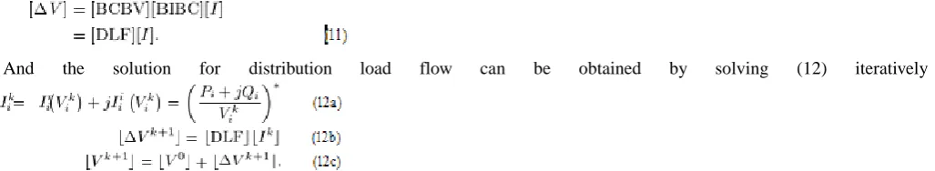
C. Solution Technique DevelopmentsThe BIBC and BCBV matrices are developed based on the topological structure of distribution systems. The BIBC matrix represents the relationship between bus current injections and branch currents. The corresponding variations at branch currents, generated by the variations at bus current injections, can be calculated directly by the BIBC matrix. The BCBV matrix represents the relationship between branch currents and bus voltages. The corresponding variations at bus voltages, generated by the variations at branch currents, can be calculated directly by the BCBV matrix. Combining (7b) and (10b), the relationship between bus current injections and bus voltages can be expressed as
And the solution for distribution load flow can be obtained by solving (12) iteratively
According to the research, the arithmetic operation number of LU factorization is approximately proportional to . For a large value of N, the LU factorization will occupy a large portion of the computational time. Therefore, if the LU factorization can be avoided, the load flow method can save tremendous Computational. From the solution techniques described before, the LU decomposition and forward/backward substitution of the Jacobian matrix or the Y admittance matrix are no longer necessary for the proposed method. Only the DLF matrix is necessary in solving load flow problem. Therefore, the proposed method can save considerable computation resources and this feature makes the proposed method suitable for online operation.
IV.TREATMENTS FOR WEAKLY MESHED NETWORKS
Some distribution feeders serving high-density load areas contain loops created by closing normally open tie-switches. The proposed method introduced before can be extended for “weakly-meshed” distribution feeders.
A. Modification for BIBC Matrix
Existence of loops in the system does not affect the bus cur- rent injections, but new branches will need to be added to the system. Fig. 3 shows a simple case with one loop. Taking the new branch current into account, the current injections of bus 5 and bus 6 will be
I’5 = I5+B6
I’6 = I6+B6 (13)
Fig 3. Simple distribution system with one loop. The BIBC matrix will be
Equation (14a) can be rewritten as
IJEDR1504087
International Journal of Engineering Development and Research (www.ijedr.org)534
The general form for the modified BIBC matrix is
The building algorithm of Step 2) for BIBC matrix can be mod ified as follows:
Step 2a)—If a new branch (Bk)makes the system become meshed (the new branch is between bus i and ), copy the elements of the ith bus column to the kth column and minus the elements of the jth bus column. Finally, fill a value to the position of the
kth row and the kth column.
B. Modification for BCBV Matrix
Considering the loop shown in Fig. 3, KVL for this loop can be written as
Combining (16) and (10a), the new BCBV matrix is
The general form for the modified BCBV matrix is
The building algorithm of Step 5) for the BCBV matrix can be modified as follows:
Step 5a)—If a new branch (Bk) makes the system become meshed, adds a new row to the original BCBV matrix by KVL. C. Modification for Solution Techniques
Substituting (15) and (17) into (11), (11) can be rewritten as
Applying Kron’s Reduction to (19), the modified algorithm for weakly meshed networks can be expressed as
Note that except for some modifications needed to be done for the BIBC, BCBV, and DLF matrices, the proposed solution techniques require no modification; therefore, the proposed method can obtain the load flow solution for weakly meshed distribution systems efficiently.
V.CONCLUSION
IJEDR1504087
International Journal of Engineering Development and Research (www.ijedr.org)535
systems. Other issues involved in the distribution system operation, such as multiphase operation with unbalanced and distributed loads, voltage regulators, and capacitors with automatic tap controls, will be discussed in future work.REFERENCES
[1] B. Stott and O. Alsac, “Fast decoupled load flow,” IEEE Trans. Power Apparat. Syst., vol. 93, pp. 859–869, May/June 1974.
[2] J. H. Teng and W. M. Lin, “Current-based power flow solutions for distribution systems,” in Proc. IEEE Int. Conf. Power Syst. Technol., Beijing,China, 1994, pp. 414–418.
[3] T.-H. Chen, M.-S. Chen, K.-J. Hwang, P. Kotas, and E. A. Chebli, “Dis- tribution system power flow analysis—A rigid approach,” IEEE Trans. Power Delivery, vol. 6, pp. 1146–1152, July 1991.
[4] K. A. Birt, J. J. Graffy, J. D. McDonald, and A. H. El-Abiad, “Three phase load flow program,” IEEE Trans. Power Apparat. Syst., vol. PAS-95, pp. 59–65, Jan./Feb. 1976.
[5] D. Shirmohammadi, H. W. Hong, A. Semlyen, and G. X. Luo, “A com- pensation-based power flow method for weakly meshed distribution and transmission networks,” IEEE Trans. Power Syst., vol. 3, pp. 753–762, May 1988.
[6] G. X. Luo and A. Semlyen, “Efficient load flow for large weakly meshed networks,” IEEE Trans. Power Syst., vol. 5, pp. 1309–1316, Nov. 1990.
[7] C. S. Cheng and D. Shirmohammadi, “A distribution system analysis,” IEEE Trans. Power Syst., vol.10, pp. 671–679, May 1995.
![Fig 1. A three phase line section model. Carson and Lewis [2].A 4 X 4 matrix, which takes into account the self and mutual coupling effects of the unbalanced three phase](https://thumb-us.123doks.com/thumbv2/123dok_us/8341608.1381622/2.595.200.396.58.145/section-carson-lewis-matrix-account-coupling-effects-unbalanced.webp)