IJEDR1303064 INTERNATIONAL JOURNAL OF ENGINEERING DEVELOPMENT AND RESEARCH | IJEDR Website: www.ijedr.org | Email ID: [email protected] 320
Performance Analysis of Voltage Droop Control of
DC Micro-Grid
Fenil V Gadhethariya
PG Student,Electrical Department, School of Engineering, RK University, Rajkot, Gujarat, India
[email protected]
Abstract— The work presents a performance study of a dc micro-grid when it is used a voltage droop technique to regulated the grid voltage and to control the load sharing between different sources like Photovoltaic cell , Fuel Cell, DG Set, Batteries, etc. A small model of a dc micro-grid comprising micro-sources and loads was implemented in the Matlab environment. Some aspects about centralized (master-slave) and decentralized (voltage droop) control strategies as well as the procedures to design the controllers, with droop control, are presented and discussed.
Index Terms—dc-dc converter, dc micro-grid, voltage droop control.
I. INTRODUCTION
Micro-grid (µG) is a electrical network comprising loads, micro-sources (µS) and communication & automation systems. These µS, also called distributed sources (DS), increase the offer of energy, the reliability and the efficiency of electrical power systems since they are able to operate close to loads and connected to or not to another electric power network [1].
Nowadays, loads like lighting systems and electronic equipments (e.g. computers and peripherals communication devices, tv sets among others) are responsible for about 35 % of the electricity consumption in residential and commercial applications [2].
DC bus voltage control and its stationary and dynamic behaviour are investigated. The target system in the study is a distributed power system based on renewable energy sources. Several different DC bus voltage control schemes exist [1], of which two seem commonly used: master-slave and droop control. The master-slave method strongly relies on fast communication between the source and load converters. One of the converters, referred to as the master, is responsible for controlling the DC bus voltage and distributing power references to the other source converters. In this paper voltage droop control is used. Droop control does not require any communication between the converters. Instead, the DC bus voltage is measured at each source converter and all the source
converters contribute to balance the total power consumed by the loads and the losses of the DC power system. In common voltage droop control, the DC bus voltage decreases linearly as the DC side current, or in some cases power, of the converter increases, in order to give stable operation.[11]
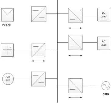
Fig. 1 shows an example of a generic dc micro grid with micro-sources, energy storage systems, dc and ac loads. Static converters connect all devices to the dc grid. A dc-ac converter is used as interface between the dc µG and the ac electric distribution network. This converter is blocked in the case of islanded operation of the dc micro-grid.
In this scenario, an important issue related to the operation of dc micro-grids is the dc bus voltage regulation. Two types of voltage control are commonly used in the literature: master-slave and voltage droop. The master-slave method depends on the communication between the interface converters. The master converter controls the voltage of the dc bus and sends
IJEDR1303064 INTERNATIONAL JOURNAL OF ENGINEERING DEVELOPMENT AND RESEARCH | IJEDR Website: www.ijedr.org | Email ID: [email protected] 321 reference signals to other converters. In the method of voltage droop, the dc bus voltage is measured at the points of coupling of the converters and it is used to calculate the amount of energy that each load or source will consume or supply.
II. CONTROL OF PARALLELED CONVERTERS
The paralleling of power sources in micro grid applications through power electronics modules offers a number of advantages over the utilization of a single high power converter [4]. Two different methods can be used to control paralleled converters on a micro-grid: master-slave and voltage droop [6]. In this section some particularities of each method will be presented.
A.Master-Slave Control
Fig. 2 Schematic diagram of Master Slave Control
Figure 2 shows the block diagram of the master-slave control scheme. In this figure, each block is composed by a dc source, a static converter and its controller. The first block, the master module, controls the grid dc bus voltage while the other blocks, the slaves, are current controlled. Despite of the fully controllable load sharing [9], this control scheme has the disadvantage of needing a fast communication channel since the reference currents for slave converters are provided by the master block. The loss of the communication link or mal-functioning of the master block can shut down the whole system [7] and [8]. Thus, to avoid or reduce the probability of failure, this system should be design with some redundancy.
B.Voltage Droop Control
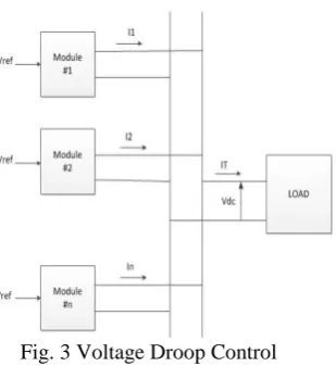
Figure 3 shows the block diagram of the voltage droop control scheme. Each droop controller emulates an impedance behaviour reducing the converter output voltage with the
Fig. 3 Voltage Droop Control
increase of the supplied current. This strategy promotes the current sharing between paralleled converters connected in the dc micro grid without the need of a central control.
III. THE VOLTAGE DROOP DESIGN A.PV Cell
IJEDR1303064 INTERNATIONAL JOURNAL OF ENGINEERING DEVELOPMENT AND RESEARCH | IJEDR Website: www.ijedr.org | Email ID: [email protected] 322 with no or low loads charges the battery, while at times with no or too low solar radiation the loads are met by discharging it. A charge controller supervises the charge process in order to ensure a long battery lifetime. Grid connected system is more applicable in the urban areas where the residents can easily get power supply from utility grid and transmit back the excesses power generating from a photovoltaic (PV) array.
PV ARRAY 50 KW OUTPUT: Isc = 87.2
Voc = 888 I r = 79.2 V r = 704 V= I*R
888 = 87.2 R R = 10.18 Ω
B. DC-DC CONVERTER (BOOST CONVERTER):
Used for converting one level of dc voltage to another level of dc voltage. Boost converter provides an output voltage greater then the source voltage Operate in two basic mode
o Continuous conduction mode o Discontinuous conduction mode
In CCM the output voltage of a converter depends on the input voltage and duty cycle.
In DCM the output voltage depends on several other parameters as well (such as inductor value, load current, switching period).
C. INVERTER:
The grid connected application requires that the dc is converted into ac before the power can be fed into the grid. There are two types of inverter
o Voltage source inverter o Current source inverter
By controlling the freq of gate pulses we can control the freq. of the o/p AC voltage. It is desirable to get an ac voltage of 50Hz.
D. FUEL CELL
The conversion of hydrogen into electricity can be achieved by different methods such as fuel cell and combustion reactions. The advantage of the fuel cell reaction is its higher overall conversion efficiencies.
The fuel cell principle was discovered by the Englishman William Robert Grove in 1839. The technical development of fuel cells started shortly after World War II when Francis T. Bacon of Cambridge, England, successfully developed a high pressure fuel cell. Subsequently alkaline fuel cells (AFC) and proton exchange membrane fuel cells (PEMFC) were developed for space programs (Gemini, Apollo, Space-lab). In the early 1970s, the development of phosphoric acid fuel cells (PAFC), high temperature molten carbonate (MCFC), and solid oxide fuel cells (SOFC) started.[4]
IJEDR1303064 INTERNATIONAL JOURNAL OF ENGINEERING DEVELOPMENT AND RESEARCH | IJEDR Website: www.ijedr.org | Email ID: [email protected] 323 Advantages and disadvantages of fuel cells
The fuel cell is important for terrestrial applications of the hydrogen technology, because it combines a relatively high efficiency with a very low environmental emission. In addition, it operates at a constant temperature, and the heat from the electrochemical reaction is available for co-generation applications. Fuel cell power plants can be configured to use a wide variety of fuels and produce a wide range of electrical outputs. Also, these plants by operating on hydrogen and oxygen offer high energy density. Therefore, large energy outputs can be produced from a system with a relatively small weight and volume. Thus, a fuel cell is a preferred power generator in remote applications where system weight and volume are important parameters. Other advantages of fuel cells and fuel cell plants and are:
Direct conversion of chemical to electrical energy.
Excellent characteristics, even with partial loading.
High availability of lower temperature units.
Fuel flexibility.
Zero or very low noise except for occasional vibrations. Disadvantages
Relatively high costs compared to conventional power sources.
Life time limitations (no confirmed knowledge about real life time).
Decreasing electrical efficiency as function of the operating life time.
Special treatment of fuel (H2) is necessary.
Noble materials are needed for membranes and electrodes, e.g., platinum is one of the most effective catalysts.E. POWER FLOW
The power flow of the components in the proposed DC micro-grid is shown in Fig. 4. The sum of the output power of the photovoltaic array, the wind power generator and the fuel cells is defined as PDG in (1).
PDG = PWG+PPV +PFC (1)
The DGs supply unidirectional power to the DC micro-grid and play a role as the main energy source. Since energy storage elements control the power balance of a DC micro-grid by charge and discharge, the power flow is bidirectional and the reference power for the elements is in (2). When the energy storage elements reach the state of full charge or discharge, the excessive power is supplied to or obtained from the AC grid, as shown in (3). The load demands unidirectional power from the micro-grid. According to a varying load demand, the energy storage element realizes a power balance, and thus it makes a continuous high-quality power supply to the load possible.
PES = PDG – PLOAD (2) PBULK = PDG – PES – PLOAD (3)
FIG.4 POWER FLOW IN DC MICRO-GRID
The power management method is analyzed in the both grid tied mode and in the islanded mode. A grid-tied converter has control over the DC grid voltage in the grid-tied mode and energy storage elements have control in the islanded mode. A super-capacitor and a battery ensure a high quality power supply to the load in both modes.[9]
IV. SIMULATION AND RESULT
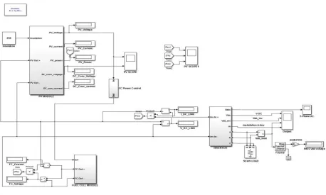
IJEDR1303064 INTERNATIONAL JOURNAL OF ENGINEERING DEVELOPMENT AND RESEARCH | IJEDR Website: www.ijedr.org | Email ID: [email protected] 324 Fig. 5 Droop Control of DC Micro-Grid
Complete simulation was tested with different radiance of sun and different load condition as given below:
1) Simulation result at 250 irradiance
2)Simulation result at 1000 irradiance
IJEDR1303064 INTERNATIONAL JOURNAL OF ENGINEERING DEVELOPMENT AND RESEARCH | IJEDR Website: www.ijedr.org | Email ID: [email protected] 325 V. CONCLUSION
A DC micro-grid has been configured by connecting the developed models and a power management method has been proposed for the islanded mode. Simulation results have verified that power management method ensures a secure power supply and efficient operation of the proposed DC micro-grid in the Droop Control Method. The developed DC micro-grid provides a basic research foundation and it can be easily extended to a DC dispatch system and a smart grid.
This Model can use to supply power to small scale industries, villages and remote location and also used in marine application.
In this paper I describe operation modes and control methods of a DC micro-grid. A micro-grid can operate in a grid connected mode or in an islanded operation mode. From the viewpoint of the operating mechanism to current sharing and output voltage management, control methods can be classified as an active load sharing and droop methods. The main difference between aforementioned control methods is that droop control methods do not require fast communication between components (i.e. generation sources and storage devices), thus improving system reliability and flexibility at the cost of the DC link voltage level stability.
REFERENCES
[1] R. H. Lasseter and P. Paigi, ―Micro-grid : A conceptual solution,‖ in 35th Annual IEEE Power Electronics Specialists Conference, pp. 4285–4290, 2004.
[2] S. Papathanassiou, D. Georgakis, N. hatziaqyriou, A. Engler, and C. Hardt, ―Operation of a prototype Micro-grid system based on micro-sources equipped with fast-acting power electronics interfaces,‖ IEEE PESC 2004, Vol.4, pp. 2521-2526, Jun. 2004.
[3] Rodrigo A F. Ferreira, Henrique AC. Braga, Andre A Ferreira and Pedro G. Barbosa, ―Analysis of Voltage Droop Control Method for dc Micro-grids with Simulink: Modelling and Simulation‖
[4] B. Todd. Dc micro-grids: a new source of local power generation. Renewable Energy, 2009. http://www.renewableenergyfocus.com.
[5] P. Karlsson. ―DC Distributed Power Systems - Analysis, Design and Control for a Renewable Energy System‖. Ph.D. thesis, Department of Industrial Electrical Engineering and Automation, Lund U niversity, Sweden, 2002.
[6] Juanjuan Sun. ―Dynamic Performance Analyses of Current Sharing Control for DC/DC Converters‖. Ph.D. thesis, Faculty of the Electrical and Computer Engineering, Virginia Polytechnic Institute and State University, 2007.
[7] Ji-Heon Lee, Hyun-Jun Kim, Byung-Moon Han, Yu-Seok Jeong, Hyo-Sik Yang, and Han-Ju Cha, ―DC Micro-Grid Operational Analysis with a Detailed Simulation Model for Distributed Generation‖, Journal of Power Electronics, Vol. 11, No. 3, May 2011.
[8] Marko Gulin, University of Zagreb, Faculty of Electrical Engineering and Computing Department of Control and Computer Engineering Unska 3, 10000 Zagreb, Croatia, ―Control of a DC Micro-grid‖.
[9] J. H. Lee and H. J. Kim and B. M. Han and Y. S. Jeong and H. S. Yang and H. J. Cha, ―DC Micro-grid Operational Analysis with a Detailed Simulation Model for Distributed Generation,‖ Journal of Power Electronics, vol. 11, no. 3, pp. 350–359, 2011.
[10] J. M. Guerrero and J. C. Vasquez and J. Matas and L. G. de Vicuna and M. Castilla, ―Hierarchical Control of Droop-Controlled AC and DC Micro-grids — A General Approach Toward Standardization,‖ IEEE Transactions on Industrial Electronics, vol. 58, no. 1, pp. 158–172, 2011.
[11] Z. Jiang and X. Yu, ―Hybrid DC- and AC-Linked Micro-grids: Towards Integration of Distributed Energy Resources,‖ in Energy 2030 Conference, pp. 1–8, 2008.