ISSN (Print) : 2320 – 3765 ISSN (Online) : 2278 – 8875
I
nternational
J
ournal of
A
dvanced
R
esearch in
E
lectrical,
E
lectronics and
I
nstrumentation
E
ngineering
(An ISO 3297: 2007 Certified Organization)
Vol. 5, Issue 1, January 2016
Development of GUI and Simulink for
Determination of Storage System Capacity for
Wind Power Generation
P.Varma
1, U.Jawadekar
2, Dr.S.Paraskar
3Assistant Professor, Dept. of E&P, P.R.Pote (Patil) College of Engineering, Amravati, Maharashtra, India1
Associate Professor, Dept. of E&P, SSGM College of Engineering, Shegaon, Maharashtra, India2
Professor, Dept. of E&P, SSGM College of Engineering, Shegaon, Maharashtra, India3
ABSTRACT: The capacity of battery storage system (BESS) for wind power generation is computed. Battery characterstics and cost for power dispatched is described. For the design of battery energy storage system a graphical user interface and simulation has been developed. Proposed method allows observing, analyzing and calculating the capacity and cost of battery energy storage system so as to determine life cost of battery system for time period. A GUI (Graphical User Interface) figure file is built in MATLAB for determination of battery power, battery energy cost for power dispatch. Simulation shows the respective characterstics of battery switching and operation. Wind power has quality of not being steady and the solution to this gives steady dispatched power to grid. A capacitor is used to smoothing DC-link voltage.
KEYWORDS: Battery energy storage system (BESS), battery power, battery capacity, DC-Link Capacitor, Graphical User Interface, wind power.
I. INTRODUCTION
It is well known that fossil fuels are finite resources and will be completely depleted one day. Wind power is the rising source of renewable energy, only main problem with wind energy is it gives unsteady delivered power, which is the mainly because of unsteady nature of wind. Battery energy storage system (BESS) can be place into the category of efficient solutions because of role it plays in a power system. The capacitor and BESS arrangement is to smoothing and power quality enhancement purpose. The literature shows an increasing interest in this subject from last few years. In choosing of battery lead acid battery is considered because of its long term power dispatch capacity and
compatibility. To describe battery energy storage capacity, value of power to be dispatch needs to be identified. BESS
is also shown to be cost-effective for use in power systems. Thus, the present work describes a methodology to calculate the expected BESS capacity for the determination of daily load levelling. The BESS power and energy capacities corresponding to load power dispatched will be determined with the proposed methodology.
Fig. 1Variable speed wind turbine, PMSG with interconnection to the grid BESS
II.SYSTEM DISCRIPTION
With the advantage of mainly no gear system, control of reactive power and decrease in cost with increase in turbine rating permanent magnet synchronous generator (PMSG) is becoming famous for wind power generation. PMSG is connected with the grid by a generator side converter BESS and grid side converter thus with the arrangement variable ac frequency at the generator terminal is converted to steady grid frequency at the output side. The generator turbine connection with BESS which considered in this paper, as depicted in Fig. 1.shows that the kinetic energy of wind captured by the turbine blades is converted into mechanical energy and then through the PMSG into electrical power,
denoted by Pw .As the main objective of this paper is capacity of the BESS, so random number is taken as wind data
and wind power Pw is defined. Machine side converter and grid side converter is connected through capacitor and
battery energy storage system. Capacitor can be used as filter as well as constant voltage source which supply or
absorbed energy of dc link voltage. It is also assume that dispatch power Pdis supplied constant over time period. The
output power of battery is Pb. The dispatch power can be controlled by adjusting dc link voltage which can be adjusted
by changing modulation index of machine side converter. Grid side converter converts the dc power into an alternating
at grid frequency and also controls the reactive power flow.The output of wind turbine is shown in fig.2
III.BESS CONSTRAINTS
A. Power and Energy Capacities
The battery power can be described by
Pb = Pw - Pd (1)
Where Pw is wind power generated from turbine and Pd is dispatched power. It can be say that, for value of dispatch
power Pd, the corresponding value of maximum battery power Pb,max determines the BESS power capacity. It is
consider that BESS capacity has to be specified to be at least as large as the corresponding Pb,max. In a same way,
BESS energy capacity can be described. Energy capacity has to be at least maximum component corresponding Pd,
Eb max.
ISSN (Print) : 2320 – 3765 ISSN (Online) : 2278 – 8875
I
nternational
J
ournal of
A
dvanced
R
esearch in
E
lectrical,
E
lectronics and
I
nstrumentation
E
ngineering
(An ISO 3297: 2007 Certified Organization)
Vol. 5, Issue 1, January 2016
B. Battery Model
The lead acid model is considered for a proposed model. Lead acid battery is considered to be more suitable for long term operations. Battery model is considered from reference paper, explain by Ceraolo.
C. Economic Benefits
An economic benefits can be achieved by, evaluation of cost required for power dispatched per hour and then for year. It is need to be specified that how much percentage of generation value is sold to the grid. In this paper it is considered for 70 and 75 percent. The benefit in per hour for dispatching power is explain in reference paper „Determination of battery storage capacity in energy buffer for wind farm‟ which can be calculated as,
B = αPd - βPb,max - γ Ebmax (2)
Where α is the unit price of the wind energy (in rupees per
Kilowatt-hour) sold to the grid, and β (in rupees per kilowatt) and γ (in rupees per kilowatt-hour) are the amortized
BESS capital costs per hour over time period.
IV.SIMULINK MODEL
The Simulink model has been developed as proposed model shown in fig.1 Wind speed, air density, power coefficient and blade length is given input to the wind turbine. Wind turbine is connected with permanent magnet synchronous generator (PMSG) which connected to grid through BESS and capacitor. Circuit breaker is provided for automatic switching of BESS while charging and discharging process by embedded MATLAB function.
Table 1.Simulink parameters: Wind turbine
Sr.No. Parameters value
1 Rating 2.1 MW
2 Air density 1.23 kg/m3
3 Blade length 52 m
4 Power coefficient 0.4
5 Rated wind speed 12m/s
Wind turbines work by converting the kinetic energy in the wind first into rotational kinetic energy in the turbine and then electrical energy that can be supplied through grid network. Simulink parameters for wind turbine considered for 2.1 MW given in table 1 The wind power can be calculated by,
Pavail= 1/2 ρAV3 Cp (3)
Where, ρ is Air density in kg/m3
A is Swept area of blades V is Wind speed m/sec Cp Power coefficient
Simulink parameters for wind turbine considered for 2.1 MW given in table 2. A permanent magnet synchronous generator is a generator where the excitation field is provided by a permanent magnet instead of a coil. the magnetic field of the rotor is produced by permanent magnets. With the advantage of mainly no gear system, control of reactive power and decrease in cost with increase in turbine rating permanent magnet synchronous generator (PMSG) is becoming famous for wind power generation.
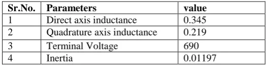
Table 2.Simulink parameters: PMSG
Sr.No. Parameters value
1 Direct axis inductance 0.345
2 Quadrature axis inductance 0.219
3 Terminal Voltage 690
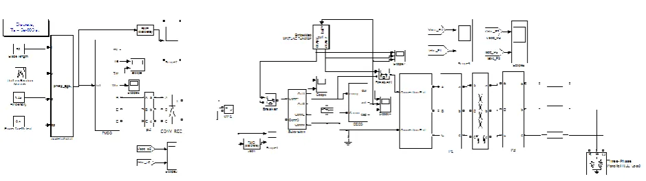
Fig.3 Simulink model of wind turbine, PMSG and grid is connected through BESS
It is considered that Model is supported system for GUI for analysisis of results in graphical context. The limitation of model is cannot processed the data for hourly basis. Although the BESS system is design in proposed method for hourly basis charging/discharging and cost benefit.
V. DEVELOPMENT OF GUI
A graphical user interface (GUI) is a graphical display that contains devices, or components, that enable a user to perform interactive tasks. Each component and the GUI itself is associated with one or more user-written routines known as callbacks. The execution of each callback is triggered by a particular user action such as a button push. In this paper, programmatic GUI approach is used.
The syntax for creating programmatically GUI is as,
function batteryprogram1 ()
The syntax used for creating figure is as,
fh = figure ('Position',[300 300 400 225]); And syntax for creating a wind power and other parameter buttons is as,
Pw = uicontrol ('property',‟value‟ …)
The editable textbox created for edit the value of wind power and other editable parameters are also created.
ISSN (Print) : 2320 – 3765 ISSN (Online) : 2278 – 8875
I
nternational
J
ournal of
A
dvanced
R
esearch in
E
lectrical,
E
lectronics and
I
nstrumentation
E
ngineering
(An ISO 3297: 2007 Certified Organization)
Vol. 5, Issue 1, January 2016
Fig. 4 GUI Block
1. Pw is wind power in MW
2. alfa is unit price of wind energy in Rs/Kwh 3. BC is Battery cost in Rs/Kwh
4. BMC is Battery maintenance cost in Rs/Kwh/Year 5. Gamma and beta are amortized cost in Rs/kw and Rs/kwh 6. Pb,max is maximum battery power in MW
7. Ebmax is maximum battery energy in MW
8. GVLLrms Generator terminal voltage in volts 9. Batt cell is voltage of 1 cell
10. BattCcapa is battery capacity in Ah 11. Ecapa is energy of 1 branch in Kwh 12. Energy of capacitor in MJ
13. Capacitor value in farad 14. Pd is dispatch power in MW 15. Vdc is DC link voltage in volt
V. RESULT AND DISCUSSION
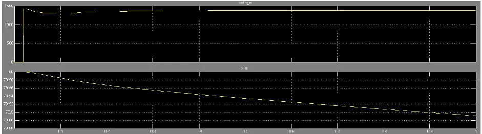
Fig.5 shows waveform of battery voltage and state of charge of battery. It is known that state of charge is a function of battery voltage. The battery nominal voltage is kept at 1408 Volts. The state of charge of battery can control by controlling voltage of battery. The voltage of battery is control by providing conditional input to circuit breaker. Conditional statement is created with embedded MATLAB function. The battery SOC needs to be controlled within a certain range so that it can prevent the forced shut down of the BESS due to overcharge or over discharge of the batteries. In Simulink model for battery state of charge control a MATLAB function with conditional statement is created. Where,
Vbat = f (SOC) (4)
Fig.6 3-phase voltage 0.987 MW
Fig.6 shows the output 3-phase voltage for wind power 2.1 MW, dispatched power 0.987MW and battery maximum power 0.987 MW as shown in GUI block. The terminal voltage of load is kept at 415 volts. It can be seen that in fig 6 voltages is rise when switching and settle at its rated voltage value.
Fig.7 DC- Link voltage
ISSN (Print) : 2320 – 3765 ISSN (Online) : 2278 – 8875
I
nternational
J
ournal of
A
dvanced
R
esearch in
E
lectrical,
E
lectronics and
I
nstrumentation
E
ngineering
(An ISO 3297: 2007 Certified Organization)
Vol. 5, Issue 1, January 2016
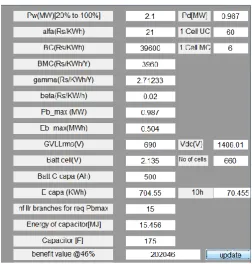
Fig.8 GUI display output for 0.987 MW dispatch power
Fig. 8 shows the GUI for 2.1 MW, dispatch power 0.987 MW and respective all parameters and cost of energy at 46% dispatched power. The cost benefit value has been calculated and displayed on GUI.The corresponding Pb,max and Ebmax are also mention in the interface block. The unit price of wind energy is taken as 21 Rs/Kwh. Respective battery cost and battery maintenance cost are displayed on GUI block .From table 1 it can be comment that the cost benefit is positive when power is sell above or equal to 47 percent of wind power.
Table 1 Cost Benefit for various value of Pw = 2.1 MW
Sr.No. % Dispatch Power (Pd) Cost Benefit in Rs.
1 45% -679954
2 46% -238954
3 47% 202046
4 48% 643046
5 49% 1084050
VI.CONCLUSION
REFERENCES
1. X.Y. Wang, D. Mahinda and S.S.Choi, “Determination of battery Storage capacity in Energy buffer for wind farm,” IEEE Trans, vol. 23, No.3, September 2008.
2. M. Ceraolo, “New dynamic models of lead-acid batteries,” IEEE Trans. Power Syst., vol. 15, no. 4, pp. 1184–1190, Nov. 2000.
3. S. Barsali and M. Ceraolo, “Dynamical models of lead-acid batteries: Implementation issues,” IEEE Trans. Energy Convers., vol. 17, no. 1, pp. 16–23, Mar. 2002.
4. T. E. Lipman andD.M.Kammen, “An assessment of battery and hydrogen energy storage systems integrated with wind energy resources in California, “California Energy Comm., PIER Energy-Related Environ. Res., Rep.CEC-500-2005-136, Sep. 20, 2005.
5. S. Mathew, Wind Energy, Fundamentals, Resource Analysis and Economics. Berlin, Germany: Springer-Verlag, 2006.
6. W. Li, G. Joos, and C. Abbey, “Attenuation of wind power fluctuations in wind turbine generators using a dc bus capacitor based filtering control scheme,” in Proc. IEEE 41st IAS Annu. Meet., Florida, Oct.2006, pp. 216–220.
7. R Jeevjyothi and D.Devraj, “A New Approach for Constant DC Link Voltage in a Direct Drive Variable Speed Wind Energy Conversion System,” J Electr Eng Technol, Vol. 10, No.: 742, 2015
8. F. Belloni, R. Chiumeo, C. Gandolfi, A. Villa, “Simulation model of a Permanent Magnet Synchronous Generator for grid studies,” International Conference on Renewable Energies and Power Quality (ICREPQ‟14), ISSN 2172-038 X, No.12, April 2014.
9. D.L Yao and SS Choi, “Determination Of The Capacity And Performance Of Battery Energy Storage Systems Used In Renewable Power Generation Schemes” th PSCC, Glasgow, Scotland, July 14-18, 2008.
10. Gustavo Azevedo, Alejandro Rolan', Alvaro Luna, Gerardo Vazquez, Daniel Aguilar, “Modelling of a Variable Speed Wind Turbine with a Permanent Magnet Synchronous Generator,” IEEE International Symposium on Industrial Electronics (ISlE 2009), Seoul Olympic Parktel, Seoul, Korea July 5-8, 2009.
11. Sandra Eriksson, Hans Bernhoff, Mats Leijon, “Evaluation of different turbine concepts for wind power” Renewable and Sustainable Energy Reviews 12 (2008) 1419–1434.