ISSN 2286-4822 www.euacademic.org
Impact Factor: 3.4546 (UIF) DRJI Value: 5.9 (B+)
Optimization of Shaped Charge Parameters for Oil
Well Perforation
ALI MOHAMMED ALI MOHAMMED ZAIN School of Mechanical Engineering Sudan University of Science & Technology
Khartoum, Sudan
EIMAD ALDEN ELHADIMUSA
Associate Professor, Aviation Department Karary University, Khartoum, Sudan
Abstract:
In the middle of the 20th century Birkhoff et al. published the first theory of shaped charge jet formation and penetration and calculated other parameter like velocities, pressures and jet diameters.
Oil well perforation problems present extremely difficult design problems due to the minimal amount of allowable space available in the well, the short stand of distances required and the hostile environment within the well.
This article aims to study effect of shaped charge parameters on penetration depth by using simulation and experimental work.
We study the effect of explosive charge type and material confinement type and thickness and compare the simulation results with experimental results to validate our work.
Key words: oil well, perforation, shaped charge, debris, Autodyn.
1-INTRODUCTION:
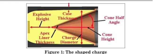
Figure 1: The shaped charge
This shape causes the gaseous products formed from the initiation of the explosive at the end of the cylinder opposite the hollow cavity to focus the energy of the detonation products to creates an intense localized force, when concentrated this force directed against a target, its capable of creating a deeper cavity than a cylinder of explosive without a hollow cavity, figure 2 illustrate shaped charge penetration. [1]
Figure 2: Penetration mechanism
The main shaped charge influencing parameters are shaped charge liner (material, wall thickness, apex angle and geometrical shape), explosive charge (type and density),
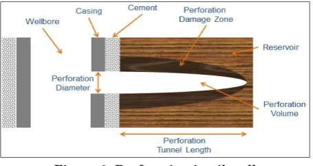
The oil well perforating is process of creating a holes or channels through the wall of the casing and cementing layer to allow oil flow from the reservoir to the wellbore , the first perforating tool which are still in use were bullet guns , the most modern perforating tools use shaped charges that are generally more adaptable to oil field perforating than the bullet guns because second one literally fires the projectile through the casing wall and can damaged it while the shaped charge can focus the energy of an explosive in a point, as shown in figure 3.[4]
Figure 3: Perforation in oil well
The design philosophy between oil well perforator and conventional shaped charge is quite different. For designing an oil well perforator must consider the stand-off is small since the space is limited inside the gun pipe, high explosive should be able to survive in a harsh environment, the cost of the perforator should be low, good perforator requires varied thickness along the length of the liner, penetration into the surrounding rock should be as deep as possible, target is non-uniform type and the fragment produced has less affect on system.[5,6]
2-SIMULATION:
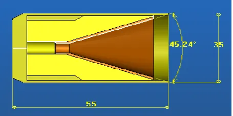
material and oil well perforation. The conical liner was composed of copper, had a 45° cone angle.
The explosive used was hexogen (RDX) with an 8.39km/s detonation velocity for material having a density of 1650 kg/m3
which is 99% of RDX and 1% wax, composition B (60%RDX & 40%TNT) with an 7.98 km/s detonation velocity for material having a density of 1660 kg/m3 and TNT with an 6.930 km/s
detonation velocity and 1650 kg/m3 density.
Three types of confinement material were used such as Steel with density 7800 kg/m3, Aluminum with density 2770
kg/m3 and Teflon with density 2200 kg/m3 with outer diameter
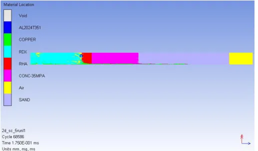
35mm and 1.5mm thickness. Figure 4 illustrate the shaped charge simulation model.
Steel target with thickness 100 mm was built to calculate penetration depth for three different types of explosives and confinement material as shown in figure 5 , while down hole oil well simulated with steel tube12.5mm thickness surrounded by 100 mm cementing layer and 300 mm concrete layer with similar rock density to perforated by 1.5 Aluminum confinement thickness and RDX explosive charge , figure 6 illustrate the perforation model.
Figure 4: Shaped charge model
Figure 6: The perforation model
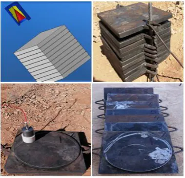
3-Experimental work: 3.1- Penetration depth:
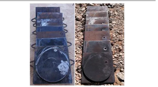
A 12 square steel plate 240X240 mm and 12.5 mm thickness were putted horizontally as penetration target and the shaped charge model was shouted vertically with electrical detonator as shown in figure 7.
Figure 7: Penetration test
3.2-Perforation depth:
Figure 8: Oil well model
4- RESULTS:
4.1- Simulation Results: 4.1.1- Penetration:
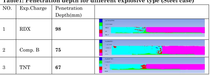
As shown in figure 9 after simulation finished, the penetration depth for three types of explosive RDX, Comp. B and TNT was tabulated in table 1, while penetration depth for three types of confinement materials tabulated in table 2.
Figure 9: Penetration simulation
Table1: Penetration depth for different explosive type (Steel case) NO. Exp.Charge Penetration
Depth(mm)
1 RDX 98
2 Comp. B 75
Table2: Penetration depth for Confinement material NO. Confi. Mat. Penetration
Depth(mm)
1 Steel 60
2 Aluminum 44
3 Teflon 34
4.1.1- Perforation:
The total perforation depth when jet breakup occurs at time 175 micro second is about 150 mm throw well case, cementing layer and reservoir rock, figure 10 illustrate perforation mechanism in oil well down hole model .
Figure 10: Perforation mechanism in oil well down whole model
4.2- Experimental Results: 4.2.1- penetration:
Figure 11: Steel plates before and after penetration test
Table 3: average penetration depth Test
No.
Confinement Type
Confinement Thickness
Explosive Charge Type
Number of
Tested Samples
Penetration Depth (mm)
1 Steel 1.5 RDX 3 93.75
2 Steel 1.5 Comp. B 3 81.25
3 Steel 1.5 TNT 3 62.50
4 Aluminum 1.5 RDX 3 81.25
5 Aluminum 1.5 Comp. B 3 58.50
6 Aluminum 1.5 TNT 3 43.20
7 Aluminum 2.5 Comp. B 3 67.25
8 Aluminum 3.5 Comp. B 3 87.50
9 Aluminum 4.5 Comp. B 3 69.50
10 Teflon 1.5 RDX 3 62.50
11 Teflon 1.5 Comp. B 3 47.00
12 Teflon 1.5 TNT 3 36.50
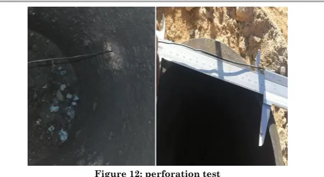
4.2.9- perforation:
Figure 12: perforation test
Table 4: average perforation depth Test
No.
Confinement Type
Confinement Thickness
Explosive Charge Type
Number of
Tested Samples
Perforation Depth (mm)
1 Steel 1.5 RDX 3 180
2 Teflon 1.5 RDX 3 123
3 Aluminum 1.5 RDX 3 157
4 Aluminum 1.5 Comp. B 3 148
5 Aluminum 2.5 Comp. B 3 215
6 Aluminum 3.5 Comp. B 3 305
7 Aluminum 4.5 Comp. B 3 230
8 Aluminum 1.5 TNT 2 087
5-DISCUSSION:
5.1-Effect of explosive type:
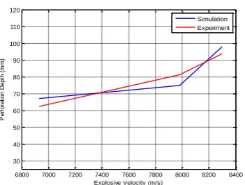
For Steel confinement we got maximum penetration when we used RDX charge, it’s about 98 mm for simulation and 93.75 mm for experimental test, this value decreased when we changed explosive charge to Comp. B or TNT, table 5 and figure 13 illustrate this phenomenon.
Table 5: Effect of explosive on penetration depth (Steel confinement)
NO Explosive Charge Type
Penetration Differences (%) Simulation Experimental
1 RDX 98 93.75 4
2 Comp. B 75 81.25 8
Figure 13: Comparison between simulation and experimental penetration for different types of explosive (Steel confinement)
5.2- Confinement Material:
Confinement material have a big effect on shaped charge penetration , as tabulated in table 6 the biggest penetration depth occurs with Steel confinement for different types of explosive , and penetration depth decrease with Aluminum and the lowest value for Teflon confinement .
Same behavior occurs in experimental test for different confinement materials and TNT explosive charge as shown in figure 14.
Table 6: Effect of Confinement material on penetration depth
Confinement Material
Penetration Depth (mm)
RDX Comp. B TNT Steel 93.75 81.25 62.50
Aluminum 81.25 58.50 43.20
Teflon 62.50 47.00 36.50
6800 7000 7200 7400 7600 7800 8000 8200 8400 30
40 50 60 70 80 90 100 110 120
Explosive Velocity (m/s)
P
e
rf
o
ra
ti
o
n
D
e
p
th
(
m
m
)
Figure 14: Comparison between simulation and experimental penetration for different types of confinement materials (TNT)
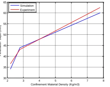
5.3- confinement thickness:
Effect of confinement thickness occurs in penetration of Steel target and perforation of oil well down whole model, as shown in table 7&8 and figure 15&16 the penetration depth increase with increasing of confinement thickness till 3.5 mm and start to decrease with increasing of confinement thickness.
Table 7: Effect of Confinement thickness on penetration depth Test No. Confinement Type Confinement Thickness Explosive Charge Type
Number of
Tested Samples
Penetration Depth (mm)
1 Aluminum 1.5 Comp. B 3 58.50
2 Aluminum 2.5 Comp. B 3 67.25
3 Aluminum 3.5 Comp. B 3 87.50
4 Aluminum 4.5 Comp. B 3 69.50
Figure 14: Effect of Confinement thickness on penetration depth
2 3 4 5 6 7 8
30 35 40 45 50 55 60 65
Confinement Material Density (Kg/m3)
P e n e tr a ti o n D e p th ( m m ) Simulation Experiment
1 1.5 2 2.5 3 3.5 4 4.5 5
55 60 65 70 75 80 85 90
confinement thickness (mm)
P e n e tr a ti o n D e p th ( m m )
Table 8: Effect of Confinement thickness on perforation depth Test No. Confinement Type Confinement Thickness Explosive Charge Type
Number of
Tested Samples
Perforation Depth (mm)
1 Aluminum 1.5 Comp. B 3 148
2 Aluminum 2.5 Comp. B 3 215
3 Aluminum 3.5 Comp. B 3 305
4 Aluminum 4.5 Comp. B 3 230
Figure 15: Effect of Confinement thickness on perforation depth
7. CONCLUSION
In this work we used Autodyn-2D to simulate the effect of explosive type and confinement material and thickness on penetration and perforation depth.
Two types of experiments were done to validate the simulation work.
The results of simulation show good agreement with experimental results, so we can use Autodyn to simulate other different parameters.
Software simulation can use to design shaped charge and solve many kinds of problem because it’s very economic and safe and faster than experimental tests.
The RDX charge gave the best result with Steel confinement and 3.5 mm thickness.
1 1.5 2 2.5 3 3.5 4 4.5 5
140 160 180 200 220 240 260 280 300 320
confinement thickness (mm)
P e rf o ra ti o n D e p th ( m m )
Acknowledgments
The authors are grateful to School of Mechanical Engineering, Sudan University of Science & Technology SUST and Grater Nile Petroleum Operation Company GNPOC for their help and support.
REFERENCES:
[1] Walters, W. P. & Zukas J. A. “Fundamentals of shaped charges”, New York: Wiley Puplication, 1989.
[2] Ali Mohammed Zain, Eimad Alden Elhadi, “Simulation of 85 mm Shaped Charge Jet tip Velocity and Penetration ”, International Journal of Engineering Sciences Paradigms and Researches (IJESPR) (Vol. 44, Issue 01), July 2017.
[3] LLOYD, R. M. 1998. Conventional Warhead Systems Physics and Engineering Design, American Institute of Aeronautics and Astronautics.
[4] SHORT, J. A., Drilling: a source book on oil and gas well drilling from exploration to completion, PennWell Books. 1983. [5] LEE, W. H. 2006. Computer Simulation of Shaped Charge Problems, World Scientific.