Binarization Methods of Sinusoidal Pattern Based on Dithering
3-D
TechniqueZhang Yi 1 , Zhao Xincheng 2 *, Yan Xin 2
1. School of Electrical and Information, Jiangsu University of Science and Technology, Zhenjiang,
212003, China
2.Department of Information Studies,University College London, London, WC1E 6BT, UK
2. School of Electrical and Information, Jiangsu University of Science and Technology, Zhenjiang,
212003, China
Abstract
3-D shape measurement with projector defocusing can eliminate projector nonlinearity in real-time three-dimensional shape measurement, improve the effect of the high frequency harmonics and accuracy of measurement, but different filters and scanning methods have different effects on the accuracy. In this paper, using different filters and scanning methods generating binary dithered fringe patterns based on projector defocusing, combined with phase shift algorithm, measure performance of measurement in phase measuring error and root mean square error as an index. As a result, the precision using Sierra dithering filter is the best; spiral scanning can improve the accuracy than horizontal scanning and Hibert scanning, especially for large period fringe measurement. Simulations and experiments are carried out to verify the proposed method. The results provide the basis for 3-D shape measurement using projector defocusing. Keywords:measurement; dithering; scan path; fringe projection; defocusing; fringe analysis
1 Introduction
3-D measurement technique with fringe projection is widely used in machine vision systems, manufacturing industry, reverse engineering and medical diagnosis etc, as it has the advantage of non-contact, high speed and precision [1-3]. Traditional fringe projection technology is to use a projector to sinusoidal grating projection on the reference plane and the object being measured respectively. The image modulated under the camera is sent to the computer for processing through the image acquisition card, and then calculating the corresponding relationship between the phase and the surface height. 3-D information of objects can be known by the calibration parameters of the system. However, the traditional sinusoidal fringe need 8 bits and the measuring speed will also be restricted because of the biggest frame for the projector.
measurement accuracy, and improve the utilization rate of light energy. People have done a lot of research in binary image. S.Y. Lei and Zhang.S put forward projecting 1 bit binary grating, proving that the binary defocusing technology of sinusoidal fringe projection can be overcome by the nonlinear effect of gamma. And it is not necessary that the CCD camera and the projector keep synchronized accurately. And the CCD exposure time also do not need precise control. To generate binary stripe [4-6]. Ayubi put forward using the pulse width modulation technology [7]. Eliminating harmonic power electronic system, Wang and Zhang put forward the optimization method of pulse modulation [8-12]. This method can eliminate the specific order harmonic of specific order. Getting sine fringes of high quality by defocusing, it has got great improvement in terms of accuracy of measurement. But this kind of modulation was on the direction of one dimensional optimization and it has poor effect when the grating period is larger.
Image dithering technique is a research technique in the field of image processing, which is widely used in printing field, using two gray scale 0 and 255 to approximately show image gray scale with more gray. Image dithering algorithm commonly used has random dither [13], ordered dither [14] and error diffusion dither [15], etc. Wang.Y and Zhang.S produce binary grating using orderly Bayer dither [16], later Lohry.S and Zhang.S use error diffusion dither to generate binary grating [17], and put forward the optimization method [18]. But it turned out that the actual measuring only applies to the period of grating, does not apply to small cycle of the grating. And its optimization algorithm has large computation, and it has limit to improve the precision. This paper analysis different filter and scanning path, getting better sine grating through defocusing, thus improving the accuracy of measurement. Simulation and experiments show that the Sierra filter is superior to other filter, and the spiral scanning method is superior to other scanning method. A combination of these two to make actual measurement, not only suitable for a large grating, but also applied to a small grating.
2 Principle of three-dimensional measurement system of raster projection based
on defocusing technique
The method of defocused grating projection is to use a projector to make 1 bit binary grating through appropriate defocusing, into a sinusoidal grating projection on the reference plane and the object being measured respectively. The image modulated grating under the camera, is sent to the computer for processing through the image acquisition card, and then calculating the corresponding relationship between the phase and the surface height. 3-D information of objects can be known by the calibration parameters of the system.
Phase shift method is a more mature algorithm for solving the main value of phase and has advantages of higher precision and operation speed. This article uses four step phase-shift method to solve the main phase. For four step phase-shift method, adjacent grating phase shift is / 2, and four phase shift raster images can be expressed as:
'
''
1 , , , cos ,
I x y I x y I x y x y (1)
'
''
2 , , , cos , + / 2
I x y I x y I x y x y (2)
'
''
3 , , , cos ,
'
''
4 , , , cos , 3 / 2
I x y I x y I x y x y (4)
Where n is 0,1,2,3. In
x y,
is the gray value of the n image, I'
x y,
is the background valueof stripe light intensity, I'
x y,
is the intensity of modulation,
x y,
is the unknown phasefield. According to the equation 1 to 4, we can get the phase principal value:
4 21 3
, arctan I I x y
I I
(5)
The domain of
x y, is [ , )through the formula (5). The continuous and completephase value
x y, is:
x y,
x y, 2k x y
, (6)
Where k x y
,
is integer, representing the grating order on the point (x, y). Phase unwrapping method has time domain method and the airspace method. Generally, time-domain method has high precision than the airspace method. This article uses the gray scale code law to expand phase.3 Dithering algorithm
3.1 Bayer dithering algorithm principle
Bayer dithering technique is to compare each original pixel values of the original map with the corresponding elements in Bayer dither matrix. According to Bayer nucleus to quantify the corresponding pixel of the original map. If the gray value is larger than the nuclear, this pixel value becomes 1, otherwise become 0. Different nuclei will form a completely different jitter effect. We found that when using 2N (N is an integer) dimension of Bayer nuclear, it is best to solve high-order harmonics. We can conclude it as:
1
0 2 3 1 M
(7)
Greater Bayer nuclear can be defined as: 1 4 4 2
4 3 4
n n n
n
n n n n
M M U
M
M U M U
(8) Where Un is the matrix of n*n.
3.2 Principle of error diffusion dithering algorithm
The formal (9) represents the principle of error diffusion:
,
, , , ,
m n S
u i j g i j h m n e i k j l
(9)Where g i j
, is the original image, u i j
, is the gray scale value of the original image and thesurrounding pixels after the quantized error diffusion. The quantized error e i j
, of the pixel atthe point
i j, spread to a plurality of adjacent pixels by a 2-D weight function h(m, n). And h (m, n) is also known as error diffusion kernel.Next, the (x, y) at the pixel was binarized by the threshold, obtaining the image pixel jitter of the final output. That is:
255, , ,
0, ,
u i j T b i j
u i j T
(10)
Where the threshold is generally taken 128.
While the quantization error e i j
, in the equation (9) is the difference of gray valuesbetween u i j
, and the output pixel b i j
, :
,
, ,e i j u i j b i j (11) Repeating these steps and processing in a certain way, we ultimately get the binary dithering image. Kernel function is the most critical parameter in error diffusion. It corresponds to a different error diffusion dithering algorithm when selecting a different kernel function.
From the principle of the error diffusion algorithm, the key factor is the choice of the filter h (m, n) and a scan order of selection.
This paper selects filter kernel:
Floyd-Steinberg filter:
,
1 73 5 1
16 x h m n
(12)
Sierra filter:
,
1 21 1
4 x h m n
(13)
Burkers filter:
,
132
h m n
x 8 4
2 4 8 4 2 (14)
Here, ”-’indicates the treated pixels, and x represents the pixel currently being processed.
Scanning method has horizontal scanning method i.e. scanning from left to right for each row (FIG. 1 (a)), the helical scanning method i.e. odd-numbered rows from left to right scan, the even scan lines from right to left (as shown in Figure 1 (b) ), Hilbert curve scanning method (Figure 1 (c))).
1.Horizontal scanning is that each line scan from left to right.
3.Hilbert curve scanning.
(a) (b) (c)
Fig.1 diagram of different scanning paths. (a)horizontal scanning; (b)spiral scanning; (c)Hilbert scanning
4 Simulation and Analysis
4.1 Different filters generating sinusoidal gratings and error analysis
Observing different filters jitter grating intuitively, as shown in Figure 2. It is Bayer ordered dithering in figure 2 (a), where the asymmetry of the grating is very serious and the grating quality is poor. Figure 2 (b) - (d) are conventional (such as, horizontal scanning) Floyd-Steinberg dithering, Sierra jitter, Burkers dither, where the distribution of stripes is relatively uniform, and no obvious distortion occurs.
In order to quantitatively describe the sinusoidal grating generated from the jitter above, using a Gaussian low-pass filter to simulate the effect of the projector defocusing, then taking a line of focused bulk grating to draw its gray curve, and making comparison with a standard sinusoidal, FIG.2 (e) ~ (h). As the figure shows, the sinusoidal generated by Bayer dither is obvious poor, and the sinusoidal generated by Burkers dither has obvious bias with standard sine, and the sinusoidal generated by Floyd-Steinberg and Sierra dither is better, and of higher quality.
(a) (b) (c) (d)
0 10 20 30 40
0 0.2 0.4 0.6 0.8 1
x/Pixel
y/
In
te
n
si
ty
sinusoidal dithering
0 10 20 30 40
0 0.2 0.4 0.6 0.8 1
x/Pixel
y/
In
te
n
si
ty
sinusoidal dithering
0 10 20 30 40 0 0.2 0.4 0.6 0.8 1 x/Pixel y/ In te n si ty sinusoidal dithering
0 10 20 30 40
0 0.2 0.4 0.6 0.8 1 x/Pixel y/ In te n si ty sinusoidal dithering
(g) (h)
Fig.2 Sinusoidal comparison of dithered fringe patterns. (a)Bayer dithering; (b)Floyd-Steinberg dithering; (c)Sierra dithering; (d)Burkers dithering; (e)~(h)Sinusoidality of dithered fringe patterns
after defocusing(with filter size 5 and fringe period 25)
To further demonstrate the dither method to improve the accuracy and the applicable conditions of different dithering algorithms, taking the Gaussian filter fs 5,7,9,11,13,15 in order. And its standard deviation is
3 s
f
, to simulate defocusing degree of different projectors.
Using a four-step phase shift method and gray code method to expand phase, and then calculating the phase of relative error obtained from the grating under different conditions. Figure 3 (a) and 3 (b) respectively show, when the fringe cycles are 25 and 100, the change of the phase error because of the increasing of the degree of defocusing. Therefore, the precision of Burkers dither method is worst, while Sierra dithering method is best. It is not very stable for small cycle fringe to use dither method, but for the great cycle fringe its phase error increases with the degree of defocusing, showing a decreasing trend.
5 10 15
0.02 0.04 0.06 0.08 0.1 Filter size/pixel R e la ti v e p h a s e e rr o r/ % Bayer Floyd-S Sierra Burkers
5 10 15
0 0.05 0.1 0.15 0.2 Filter size/pixel R e la ti v e p h a s e e rr o r/ % Bayer Floyd-S Sierra Burkers
(a) (b)
Fig.3 Comparison between different dithering methods for T=25 and T=100. (a)T=25; (b)T=100
4.2 sinusoidal gratings generated from different scanning path and error analysis
consistent with the standard gratings, and this scanning method is best.
(a) (b) (c)
(d) (e) (f)
Fig.4 Sinusoidal comparison of dithered fringe patterns.(a)Floyd-Steinberg dithering on horizontal sweep; (b)Floyd-Steinberg dithering on helical sweep; (c)Floyd-Steinberg dithering on Hilbert
sweep; (d)~(f)Sinusoidality of dithered fringe patterns after defocusing(with filter size 5 and fringe period 25)
Due to the poor quality of the gratings generated from Hilbert scanning and the calculation is large, greatly reducing the speed of the experiment, so we directly analysis the horizontal scanning method and the helical scanning method. Taking the Gaussian filter
fs
5,7,9,11,13,15 in order, andits standard deviation is
fs
/
3
,to simulate defocusing degree of different projectors. Combined with the four-step phase shift method and gray code method unwrapped phase, to analyze the relative error of phase obtained in large and small periodic grating period when using the horizontal scanning and helical scanning for different filters. Figure 3 (a) ~ (c) and figure 3 (d) ~ (f) are respectively the effects of different filters when the fringe cycles are 25 and 100. It is seen in a small cycle stripes, Floyd-Steinberg filter and Sierra filters have similar results. While the helical scanning method has significantly improved in the increasing with the degree of defocusing after proper defocusing, for various filters of macro cycle stripes and Burkers filter of small stripes.5 10 15
0 0.02 0.04 0.06 Filter size/pixel R e la t iv e p h a s e e rr o r /% Floyd-S-ns Floyd-S
5 10 15
0 0.02 0.04 0.06 Filter size/pixel R e la t iv e p h a s e e rr o r /% Sierra-ns Sierra
5 10 15
0.02 0.04 0.06 0.08 0.1 Filter size/pixel R e la ti v e p h a s e e rr o r/ % Burkers-ns Burkers
5 10 15 0 0.05 0.1 0.15 0.2 Filter size/pixel R e la t iv e p h a s e e rr o r /% Floyd-S-ns Floyd-S
5 10 15
0 0.05 0.1 0.15 0.2 Filter size/pixel R e la ti v e p h a s e e rr o r/ % Sierra-ns sierra
5 10 15 0 0.05 0.1 0.15 0.2 Filter size/pixel R e la ti v e p h a s e e rr o r/ % Burkers-ns Burkers
(d) (e) (f)
Fig.5 Effects of different filters for different scanning paths on T=25 and T=100. (a)~(c)T=25; (d)~(f)T=100
5 Experiments
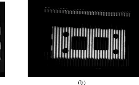
Make a vertical whiteboard as a reference plane to measure the phase and calculate the relative phase error. The camera used in the experiment(Basler acA2000-340km)is in a focused state, and the DLP projector (PHYLINA PD-L800) is at a low degree of defocusing state. Figure 6 (a) is the error diffusion dithering defocused raster image collected by the camera at intervals of 25, Figure 6 (b) is the main value of the phase of the four-step method for solving the phase shift, FIG.6 (c) is one of the line of the main value of the phase, FIG.6(d) is the phase expanded by the use of gray code method. It can be seen that the quality of defocused Sierra Lite jitter grating is higher, and the phase solved is relatively smooth.
(a) (b)
When the simulation results are on the condition that the Sierra filters and the helical scanning measurement have the best precision and the projector has a lower degree of defocusing, measuring and calculating the phase error used in the experiment of different dithering algorithm to combine with the grating in different period generated from helical scanning. As is shown in FIG. 7.
Floyd-Steinberg dithering and Sierra dithering algorithm combined with helical scanning method can not only get a phase of high quality in a small fringe period, but also maintain a low phase error when the period is large. It states that they have strong adaptability. The experiment results are consistent with the simulation results.
20 40 60 80 100 120 140 160 180 200
0 0.05 0.1 0.15 0.2 0.25 0.3 0.35
Fringe period/pixel
R
e
la
ti
v
e
p
h
a
s
e
e
rr
o
r/
%
Floyd-S Sierra-S Burkers-S Sierra-NS
Fig.7 Relative phase error of different filters on helical sweep
To test its actual feasibility, we use the jitter grating of Sierra filter in helical scanning method to measure the actual object. Using the grating of the fringe period at 25, and the measurement object is a white plastic plate with holes, which is as shown in FIG.8 (a). Figure 8 (b) is one of the four-step phase shift raster image. Figure 8 (c) is the main value of the phase solved by the method of the four-step phase shift. Figure 8 (d) is the phase map expanded by the gray scale code method. The phase finally obtained is as shown in FIG.8 (e) and the final phase for recovering the three-dimensional shape of the object is correct and smooth. Therefore, the phase obtained in the actual measurement by the error diffusion dithering grating is of relatively high quality and meets the measurement requirements.
(c) (d)
(e)
Fig.8 Measurement of an object with Sierra dithered fringe pattern on helical sweep. (a) object to be measured; (b) one of four-step phase-shifting fringe pattern; (c) wrapped phase; (d) unwrapped
phase; (e) final phase of the object
6 Conclusions
Projector defocusing technique is increasingly used in high-speed, real-time three-dimensional measurement systems, and image dithering technique is proven to solve a series of defocusing problems, such as reducing the impact of higher harmonics and overcoming nonlinear problems of projectors. In this paper, a combination of different jitter filters with different scanning generating the projection grating, significantly improves the quality of the jitter grating and the sinusoidal is ideal. Sierra jitter filter is superior to other filter, and helical scanning method is superior to other scanning methods. These two are combined at a lower degree of defocusing. Compared to the binary defocusing method, dithering algorithm can significantly improve the quality of dithering grating and reduce the phase error, and it can improve the accuracy of the overall system. Simulation and experiment results demonstrate the advantages of dithering algorithm.
Acknowledgements
This work was financially supported by National Natural Science Foundation of China (61503161).
References
[1] Gorthi S, Rastogi P. Fringe projection techniques: whither we are?[J]. Optics and Lasers in Engineering, 2010, 48: 133–140.
[2] Da Feipeng, Gai Shaoyan. A new fast phase unwrapping method[J]. Acta Optica Sinica, 2008, 28(2): 259~267.
[4] Lei S, Zhang S. Flexible 3-D shape measurement using projector defocusing[J]. Opt Lett, 2009, 34(20): 3080-3082.
[5] Lei S, Zhang S. Digital sinusoidal fringe pattern generation: defocusing binary patterns VS focusing sinusoidal patterns[J]. Opt Laser Eng, 2010, 48(4): 561-569.
[6] Xu Y, Ekstrand L, Dai J, Zhang S. Phase error compensation for three-dimensional shape measurement with projector defocusing. Appl Opt, 2011, 50(17): 2572-2581.
[7] Ayubi GA, Ayubi JA, Martino JMD, Ferrai JA. Pulse-width modulation in defocused 3-D fringe projection[J]. Opt Lett, 2010, 35: 3682-3684.
[8] Fujiata H, Yamamoto M, Otani Y, Suguro A, Morokawa S. Three-dimensional profilometry using liquid crystal grating[C]. In: Proceedings of the SPIE, vol. 5058. Beijing, China, 2003, 51-60.
[9] Yoshizawa T, Fujita H. Liquid crystal gratings for profilometry using structed light[C]. In: Proceedings of the SPIE, vol. 6000, Boston, MA, 2005, 60,000H1.
[10] Wang Y, Zhang S. Optimum pulse width modulation for sinusoidal fringe generation with projector defocusing[J]. Opt Lett, 2010, 35(24): 4121-4123.
[11] Zuo C, Chen Q, Feng F, Gu G, Sui X. Optimized pulse width modulation pattern strategy for three-dimensional profilometry with projector defocusing[J]. Appl Opt, 2012, 15(19): 4477-4490.
[12] Wang Y, Zhang S. Comparison among square binary, sinusoidal pulse width modulation, optimal pulse width modulation methods for three-dimensional shape measurement[J]. Appl Opt, 2012, 51(7): 861- 872.
[13] Purgathofer W, Tobler R, and Geiler M. Forced random dithering: improved threshold matrices for ordered dithering[C]. IEEE International Conference on Image Processing, 1994, 2: 1032-1035.
[14] Bayer B. An optimum method for two-level rendition of continuous-tone pictures[C]. IEEE International Conference on Communications, 1973, 1: 11-15.
[15] Kite TD, Evans BL, and Bovik AC. Modeling and quality assessment of Halftoning by error diffusion[C]. IEEE International Conference on Image Processing, 2000, 9(5): 909-922. [16] Wang Y, Zhang S. Three-dimensional shape measurement with binary dithered patterns[J].
Appl Opt, 2012, 51(27):6631-6636.
[17] Lohry W, Zhang S. Genetic method to optimize binary dithering technique for high-quality fringe generation[J]. Opt Lett, 2013, 38(4):540-542.