ISSN (Print) : 2320 – 3765 ISSN (Online): 2278 – 8875
I
nternational
J
ournal of
A
dvanced
R
esearch in
E
lectrical,
E
lectronics and
I
nstrumentation
E
ngineering
(An ISO 3297: 2007 Certified Organization)
Vol. 5, Issue 6, June 2016
Harmonic Reduction using Shunt Active
Power Filter
Geena Sharma1, Kanchan Jaswal2
Assistant Professor, Dept. of EE,Baddi University of Emerging Sciences & Technology, H.P, India1
Final Year M.Tech [PED] Student,Baddi University of Emerging Sciences & Technology, H.P, India2
ABSTRACT: Active power filters are the emerging devices, which can diminish harmonic pollution effectively. Normally, the shunt APF is controlled such that it eliminates the load current harmonics and supplies load reactive power to achieve harmonic free source currents at unity power factor. However, these control objectives cannot be achieved simultaneously when the supply voltages are distorted and unbalanced (non-ideal). Hence, under such situation the shunt APF should be controlled optimally to achieve a maximum possible power factor without violating the current harmonics constraints recommended by IEEE Std. 519.
Most of the proposed control strategies for power quality improvements have been reviewed with regard to performance and implementation. It has been seen that there has been a significant increase in interest of active power filters and its control methods. Model of Shunt Active Power filter is implemented with PI controller. Further simulation is done in MATLAB to verify the results.
KEYWORDS:Harmonics, Filters, Shunt active power filter, Power Quality
I.INTRODUCTION
In the recent years, Power quality (PQ) is emerging as an issue of major concern, (globally as well as nationwide) requiring accurate monitoring, in-depth analysis and adoption of planned PQ improvement initiatives. The present scenario has changed in our country, with a large proportion of the industrial, commercial and domestic load now turning out to be non-linear due to growing use of power electronics, automation, computers and information technology. Widespread use of non-linear loads degenerate the quality of power in both transmission and distribution systems.
All non-linear loads draw non-sinusoidal currents which cause distortion in the voltage waveform not only within the individual plant but also in the power supply network [3]. Harmonics propagate from one consumer to another, causing many undesirable effects on the power system. The harmonic current components do not represent useful active power due to the frequency mismatch with the source voltage [4]. A simple and effective technique for harmonic analysis is current injection model which is most commonly applied for harmonic simulation studies. This approach treats harmonic producing load as an injection current source to the system assuming steady-state condition. Consequently, all non-linearities in the system are represented as current injections of corresponding harmonic frequencies and therefore, the superposition principle can be applied.
II. LITERATURE SURVEY
ISSN (Print) : 2320 – 3765 ISSN (Online): 2278 – 8875
I
nternational
J
ournal of
A
dvanced
R
esearch in
E
lectrical,
E
lectronics and
I
nstrumentation
E
ngineering
(An ISO 3297: 2007 Certified Organization)
Vol. 5, Issue 6, June 2016
Salem Rahmani, Abdelhamid Hamadi, etal [2] proposed a combined system of a thyristor controlled reactor (TCR) and a shunt hybrid power filter (SHPF) for harmonic and reactive power compensation. The SHPF is the combination of a small-rating active power filter (APF) and a fifth-harmonic-tuned LC passive filter. A nonlinear control of APF was developed for current tracking and voltage regulation. Scheme of a SHPF-TCR compensator has been established, simulated, and implemented by using the DS1104 digital real time controller board of dSPACE. The shunt active filter and SPF have a complementary function to improve the performance of filtering and to reduce the power rating requirements of an active filter. It has been found that the SHPF-TCR compensator can effectively eliminate current harmonic and reactive power compensation during steady and transient operating conditions for a variety of loads.
Jinwei He, Xiongfei Wang, etal [3] proposed an enhanced current control approach, which seamlessly integrates system harmonic mitigation capabilities with the primary DG power generation function to utilize distributed generation (DG) unit interfacing converters to actively compensate harmonics. Moreover, a closed-loop power control scheme is employed to directly derive the fundamental current reference without using any phase locked loops (PLL). Thus concluded that the proposed power control method ensures accurate power control even when harmonic compensation tasks are activated in the DG unit.
Parag Kanjiya, Vinod Khadkikar, etal [4] explained an optimal algorithm to control three phase four wire shunt active power filter under non-ideal supply conditions. The optimization problem aiming at maximizing the power factor subject to current harmonics constraints, as per IEEE std.519 has been formulated and solved mathematically using Lagrangian formulation. The constraints on current harmonics include limits on the individual odd harmonics and individual even harmonics with THD not exceeding 5%. The detail analysis of the proposed non-iterative approach, carried out with different operating conditions and compared with the Newton Raphson method demonstrates that it always converges an optimal solution.
Quoc-Nam Trinh, etal [5] proposed an advanced control strategy to enhance performance of shunt APF. The proposed control scheme requires only two current sensors at the supply side and does not need a harmonic detector. In order to make the supply currents sinusoidal, an effective harmonic compensation methods is developed with the use of a conventional proportional-integral and vector PI controllers. The total cost to implement the proposed APF becomes lower, due to the minimized current sensors and the use of a four-switch three-phase inverter. The effectiveness of the proposed control strategy was verified through various experimental tests, where the supply current was almost perfect sinusoidal and in-phase with the supply voltage even under the distorted voltage condition.
Mauricio Angulo, Domingo A. Ruiz-Caballero, etal [6] presented simple indirect control concepts for an active power filter (APF) applications. The concepts are ideally presented to control a modified APF structure. The defined control strategy is related to the concept of virtual impedance emulation to provide high power factor in a system. This model operates at an extra ordinary low switching frequency of 5 kHz and is controlled by digital signal processor. The main feature of the strategies is their extreme simplicity since no complex current reference computations are required. It was proven that the proposed strategies are equivalent to explicit current control strategies employing a resonant type controller. These characteristics were verified through circuit simulation and in an experimental setup including a non linear rectifier load, with APF being switched at 5 kHz. This is very low switching and highlights the remarkable performance.
Fernando Briz, Michael W. Degner, etal [7] described about the selective harmonic current compensating technique using harmonic regulators, with a focus on their stability analysis and transient behavior. Due to the presence of multiple current regulators working in parallel can create unwanted couplings with the fundamental current regulator, which can result in deterioration of APF current control. Harmonic current regulators provide good solution to perfectly cancel selected harmonics injected by nonlinear loads. From the stability analysis of harmonic current regulators described in this paper, it has been concluded that the impact, that different implementation issues like sampling strategy, switching period, and use of filters having maximum number of harmonics can be cancelled by these regulators, as well as the range of gains that can be used to guarantee the stability of the system, has been established.
Junyi Liu, Pericle Zanchetta, etal [8] designed and implemented SAF for aircraft power networks using an accurate wide-band current control method based on Iterative Learning Control (ILC). The SAF control system is so designed so as to compensate harmonic currents, with a 400 Hz supply voltage. This work introduces useful design strategies to increase the error-decay speed and improve the strength of SAF control system by using a hybrid P-type ILC controller. The proposed scheme has been simulated in MATLAB Simulink environment using the circuit configuration.
ISSN (Print) : 2320 – 3765 ISSN (Online): 2278 – 8875
I
nternational
J
ournal of
A
dvanced
R
esearch in
E
lectrical,
E
lectronics and
I
nstrumentation
E
ngineering
(An ISO 3297: 2007 Certified Organization)
Vol. 5, Issue 6, June 2016
voltage interface bus between the distribution and transmission systems, in presence of large shunt capacitor banks installed only for reactive power compensation. Four CSC-based APF modules designed at 1.0 k are operated in parallel and connected to the 31.5 kV medium-voltage bus via a specially designed coupling transformer. In each APF module, a specially designed LC-type input filter eliminates the switching ripples and active damping method into the control software suppresses harmonic frequencies around the corner frequency of input filter. The resulting system can operate at relatively high frequencies in the range from 2 to 3 kHz.
Chi-Seng Lam, Wai-Hei Choi, etal [10] presented an adaptive dc-link voltage controlled LC coupling hybrid active power filter (LC-HAPF) for reducing switching loss and switching noise under reactive power compensation. In this, mathematically relation between LCHAPF dc-link voltage and reactive power compensation range is deduced and presented. Based on this analysis, the required minimum dc-link voltage with respect to different loading reactive power is deduced, and then an adaptive dc-link voltage controller for 3P4W LC-HAPF is proposed. In this paper, the dc-link voltage is classified into certain levels for selection in order to minimize the problem of dc voltage fluctuation caused by its frequent variation and reducing the fluctuation impact on compensation performance.
Yi Tang, Poh Chiang Loh, etal [11] discussed about the design, control and implementation of an LCL-filter based shunt active power filter, which can effectively compensate for harmonic currents produced by nonlinear loads in a three-phase three wire power system. With an LCL filter added at its output, the proposed SAPF offers superior switching harmonic suppression using much reduced passive filtering elements. Its output currents thus have high slew rate for tracking the targeted reference closely. Smaller inductance of LCL filter also means smaller harmonic voltage drop across the passive output filter, which in turn minimizes the possibility of over modulation, where high modulation index is desired. These advantages, together with overall system stability, are guaranteed only through proper consideration of critical design and control issues, like the selection of LCL parameters, interactions between resonance damping and harmonic compensation, bandwidth design of closed loop system, and active damping implementation with fewer current sensors. Further experimental testing of methodology has proven its effectiveness in ensuring proper damping, overall stability, and smooth transient response achieved through a more comprehensive and generalized design procedure.
Francisco [12] discussed various fundamentals of harmonic distortion and power quality, various harmonic sources, effects of harmonics on distribution system, harmonic measurement etc. Various harmonic sources discussed are harmonic from commercial loads, single-phase supply, industrial loads, dc drives, ac drives, arcing devices etc.
Santosoetal [13] discussed about non-linear loads and explained that all non-linear loads draw non-sinusoidal currents which further cause distortion in voltage wave-form not only within the individual plant but also in the power supply network. Harmonics propagate from one consumer to another, causing many undesirable effects on the power system such as overloading of power factor correction equipment, interference with communication circuits, overloading of neutral conductor etc. Mitigating the effects of harmonics, proper filtering solution has been given by the authors. The authors have also discussed about the active & passive filters for controlling harmonic distortion.
Keulenaer and Hans De [14] discussed about self assessment of Power Quality. The authors have discussed various typical power quality problems such as computer lockups, flickering screens, flickering lights, overheating of transformers at moderate loads, overheating of conductors due to skin effect, problems with power factor correction equipment, problem with specific lines, overloaded neutral, utility claims resulting from harmonics affecting supply etc. The authors have also discussed about the possible solutions for Power Quality problems. For each type of problem there is a range of possible mitigation approaches, several of which could be equally successfully applied. Different solutions given by the authors are surge protection, UPS, Bank of generators, multiple cables for harmonic loads, complete rewiring of installation, passive filters, active conditioners, neutral upsizing etc.
ISSN (Print) : 2320 – 3765 ISSN (Online): 2278 – 8875
I
nternational
J
ournal of
A
dvanced
R
esearch in
E
lectrical,
E
lectronics and
I
nstrumentation
E
ngineering
(An ISO 3297: 2007 Certified Organization)
Vol. 5, Issue 6, June 2016
In [16] IEEE STANDARD 1459-2000, various standard definitions for the measurement of electric power quantities under sinusoidal, non-sinusoidal, balanced and unbalanced conditions has been discussed. The following important features have been recognized by this trial use standard:
Power frequency, apparent, active and reactive power.
Non-fundamental apparent power which quantifies the overall amount of harmonic pollution delivered or absorbed by a load.
Current distortion power which identifies the segment of non-fundamental non- active power due to current distortion.
Voltage distortion power which separates the non-fundamental non-active power component due to voltage distortion.
Apparent harmonic power, which indicates the level of apparent power due to harmonic voltages and currents alone.
This trial use standard is meant to provide the organizations with criteria for designing and using metering instrumentation.
III. HARMONIC FILTERING SOLUTION
There are number of devices available to control harmonic distortion in the power supply networks by the use of filters. Filters are used to restrict the flow of harmonics current in the Power Systems. It is a LC circuit, which passes all frequencies in its pass bands and stops all frequencies in its stop bands. There are two basic types of filters categorized as:
Passive Filters Active Filters
Passive filters comprise inductance, capacitance and resistance elements configured and tuned to control harmonics. They are designed either to shunt the harmonic currents off the line or block their flow by tuning the elements to create resonance at a selected frequency. Active filters, on the other hand, are designed to inject harmonic currents to counterbalance existing harmonic components as they show up in the distribution system.
IV.SHUNT ACTIVE POWER FILTER
Active power harmonic filtering is a relatively new technology for eliminating harmonics which is based on the power electronics devices. An active power filter consists of one or more power electronic converters which utilize power semiconductor devices controlled by integrated circuits. The use of active power filters to eliminate the harmonics before they enter a supply system is the optimal method of dealing with the harmonics problem. . Active power filters could be connected either in series or in parallel to power systems; therefore, they can operate as either voltage sources or current sources. The shunt active filter is controlled to inject a compensating current into the utility system so that it cancels the harmonic currents produced by the non-linear load.
ISSN (Print) : 2320 – 3765 ISSN (Online): 2278 – 8875
I
nternational
J
ournal of
A
dvanced
R
esearch in
E
lectrical,
E
lectronics and
I
nstrumentation
E
ngineering
(An ISO 3297: 2007 Certified Organization)
Vol. 5, Issue 6, June 2016
The principal of active filtering for current compensation is shown in Fig.:1. The load current is non-linear due to the non-linear load. In this figure, the active filter is controlled to draw or inject a current I such that the source current I = I + I is sinusoidal.
V.BASIC COMPENSATION PRINCIPLE
Fig.:2 Filter current IF generated to compensate load-current harmonics [29]
Fig.2 shows the basic compensation principle of a shunt active power filter. It is controlled to supply a compensating current from/to the utility, so that it cancels current harmonics on the AC side, and makes the source current in phase with the source voltage. Figure.3 shows the different waveforms. Curve A is the load current waveform and curve B is the desired mains current. Curve C shows the compensating current injected by the active filter containing all the harmonics, to make mains current sinusoidal.
Fig.:3 Shunt active power filter-Shapes of load, source and desired filter current wave forms.
VI. PI CONTROL SCHEME
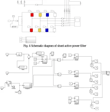
Shunt Active Power Filter is connected in shunt with the load to suppress the harmonics. The complete schematic diagram of the shunt active power filter is shown in Fig.4 while Fig. 5 gives the control scheme realization.
ISSN (Print) : 2320 – 3765 ISSN (Online): 2278 – 8875
I
nternational
J
ournal of
A
dvanced
R
esearch in
E
lectrical,
E
lectronics and
I
nstrumentation
E
ngineering
(An ISO 3297: 2007 Certified Organization)
Vol. 5, Issue 6, June 2016
Fig. 4 Schematic diagram of shunt active power filter
The error signal is fed to PI controller. The output of PI controller has been considered as peak value of the reference current. It is further multiplied by the unit sine vectors ( , ) in phase with the source voltages to obtain the reference currents (∗ , ∗ ∗ ). These reference currents and actual currents are given to subsystem, subsystem 2,
subsystem3 and subsystem 4 respectively. The difference of reference current and actual current decides the operation of switches. These switching signals after proper isolation and amplification are given to the switching devices. Due to these switching actions current flows through the filter inductor , to compensate the harmonic current and reactive power of the load, so that only active power drawn from the source.
ISSN (Print) : 2320 – 3765 ISSN (Online): 2278 – 8875
I
nternational
J
ournal of
A
dvanced
R
esearch in
E
lectrical,
E
lectronics and
I
nstrumentation
E
ngineering
(An ISO 3297: 2007 Certified Organization)
Vol. 5, Issue 6, June 2016
VII. SIMULATION RESULTS
The complete active power filter system is composed mainly of three-phase source, a nonlinear load, a voltage source converter, and a PI controller. All these components are modeled separately to simulate the system. The spectrum of different source current and voltages and load current and voltages are shown below.
Fig.:6 Three-phase source voltages without APF
Fig.:6 show three-phase voltage sources when not connected to APF. There is lot of distortion seen in phase a, phase b, and phase c. All these harmonics are mitigated by connecting an SAPF (shunt active power filter) as can be seen in fig.:7.
Fig.:7 Three-phase voltage sources with APF connected to the non-linear load.
ISSN (Print) : 2320 – 3765 ISSN (Online): 2278 – 8875
I
nternational
J
ournal of
A
dvanced
R
esearch in
E
lectrical,
E
lectronics and
I
nstrumentation
E
ngineering
(An ISO 3297: 2007 Certified Organization)
Vol. 5, Issue 6, June 2016
Fig.:8 shows the current generated by Active Power Filter, when the filter is connected to the load/. Fig 9 shows the dc link voltage.
Fig.:9 Dc link capacitance voltage (Vdc)
Fig.:10 Spectrum of current and voltage of non-linear load
Fig.:10 shows the spectrum of current and voltages of a non-linear load which is connected with the three-phase voltage source. Fig.:11 shows the spectrum of load voltage, source current and load current without APF connected to the system.
ISSN (Print) : 2320 – 3765 ISSN (Online): 2278 – 8875
I
nternational
J
ournal of
A
dvanced
R
esearch in
E
lectrical,
E
lectronics and
I
nstrumentation
E
ngineering
(An ISO 3297: 2007 Certified Organization)
Vol. 5, Issue 6, June 2016
Fig.: 12 shows the spectrum of load voltage, source current and load current when APF is connected to the system. It can be seen from the result wave-shape that APF does its work correctly by mitigating source current harmonics to great extent.
Fig.:12 Spectrum of Load voltage, Source Current and Load current when connected to APF.
Fig.:13 FFT-analysis of load current without APF
ISSN (Print) : 2320 – 3765 ISSN (Online): 2278 – 8875
I
nternational
J
ournal of
A
dvanced
R
esearch in
E
lectrical,
E
lectronics and
I
nstrumentation
E
ngineering
(An ISO 3297: 2007 Certified Organization)
Vol. 5, Issue 6, June 2016
Fig.14 FFT analysis of load current with APF
VIII. CONCLUSION
The model of the proposed new Shunt Active Power Filter is realized for mitigating harmonic distortion and power quality improvement. PI controller based Shunt active power filter is implemented for harmonic and reactive power compensation of the non-linear load. It is simulated using the highly developed graphic tool SIMULINK available in MATLAB. It is found from simulation results that shunt active power filter improves power quality of the power system by eliminating harmonics and reactive current of the load current, which makes the load current sinusoidal and in phase with the source voltage.
IX. SCOPE FOR FUTURE WORK
There is an ample and increasing scope of harmonic assessments in the present scenario in our country. The harmonic measurements and analysis carried out in the present work has brought forth some interesting and unusual findings which need further in-depth investigations.
High resolution instruments can be used for measuring inter-harmonics which can indicate the presence of non-integral harmonics in the electrical network. Harmonic simulation can be carried out on Lab VIEW to obtain a better user interface with graphic programming facility.
Experimental investigations can be done on shunt active power filter by developing a prototype model in the laboratory to verify the simulation results for PI controllers and Fuzzy controller and the result can be compared.
REFERENCES
1. IEEE Std. 519-1992, “IEEE Recommended Practices And Requirement For Harmonic Control In Electrical Power Systems”.
2. Chapman David, “The Cost of Poor Power Quality, Power Quality Application Guide, Copper Development Association, U.K, March, 2001”. 3. Santoso, Surya, Dugan, R.C, Mc. Granaghan, M.F., Beaty, H.W, “Electrical Power System Quality”, McGraw-Hill, Second Edition, 2003”. 4. Mauricio Angulo, “IEEE Transactions on Industrial Electronics, Vol.60. 7 July 2013”.
5. Czarnecki, I.S., “What is Wrong with Budeanu’s Concept of Reactive and Distortion Power and Why it should be Abandoned” IEEE Transactions on Instrumentation and Measurement, Vol. 36, 3 September,1987.
6. Francisco C. De La Rosa, “Harmonics and Power System” Sun Francisco, June, 2005.
7. Emanuel, A.E..,” On the assessment of Harmonic Pollution”’ IEEE Transactions on Power Delivery, Vol. 10, no. 3, July 1995, pp. 767-772. 8. Mostafa S. Hamad, Mahmoud I. Masoud, et al., “A shunt active power filter for a medium voltage 12-pulse current source converter using
open loop current compensation.” In IEEE Transactions on Industrial Electronics, Vol.61, No.11, November 2014 on P (5840-5850). 9. Salem Rahmani, Abdelhamid Hamadi, et al., “A combination of shunt hybrid power filter and thyristor controlled reactor for power quality.”
IN IEEE Transactions on Industrial Electronics, Vol.61, No. 5, May 2014 On P (2152-2164).
10. Jinwei He, Xiongfei Wang, et al., “Active harmonic filtering using current-controlled, grid connected DG units with close- loop power control.” In IEEE Transactions on Power Electronics, Vol.29, No.2, February 2014 on P (642-653).
11. Parag Kanjiya, Vinod Khadkikar, et al., “Optimal control of shunt active power filters to meet IEEEstd.-519 current harmonics constraints under non-ideal supply condition.” In IEEE Transactions on Industrial Electronics 2014.
12. Quoc-Nam Trinh, et al., “An advanced current control strategy for shunt APF.” In IEEE Transactions on Industrial Electronics, Vol.60, No.12, Dec 2013.
ISSN (Print) : 2320 – 3765 ISSN (Online): 2278 – 8875
I
nternational
J
ournal of
A
dvanced
R
esearch in
E
lectrical,
E
lectronics and
I
nstrumentation
E
ngineering
(An ISO 3297: 2007 Certified Organization)
Vol. 5, Issue 6, June 2016
14. Junyi Liu, Pericle Zanchetta, et al., “Control design and implementation for high performance shunt active filters in aircraft power grids.” In IEEE Transactions on Industrial Electronics, Vol.59, No.9 September 2012 on P (3604-3613).
15. Alper Terciyanli, Tulay Avci, et al., “A current source converter based APF for mitigation of harmonics at the interface of distribution and transmission systems.” In IEEE Transactions on Industrial Applications, Vol.48. No. 4 July/August 2012 on P (1374-1386).