www.ijiset.com
Study on Effect of Infill Distribution on Buildings During
Earthquake
Ebitta Joy1 and Divya Sasi2
1
Department of Civil Engineering, MBITS, Nellimattom, Kothamangalam, Kerala, India
2
Department of Civil Engineering, MBITS, Nellimattom, Kothamangalam, Kerala, India
Abstract
Strength and stiffness are the most important characteristics of any structure. Due to the architectural efficiency of masonry-infilled reinforced concrete frames, the frames are highly common structural forms for buildings. But in the current practice, stiff masonry walls are neglected and only bare frames are considered in design calculations. However, the infills can significantly modify the structural behavior of these frames, which can be detrimental to the seismic performance of buildings. Through this paper, the effect of infill distribution on buildings is studied using 3D FE models in ANSYS
Keywords: Natural period, Frames, Infill
1. Introduction
The actual seismic failure modes and performances of
infilled RC frames typically differ from those anticipated based on the original structural analyses performed by design engineers. At the present engineers’ neglect the influence of infills on overall structural performance because infills are normally considered non-structural components. The modifications of structural action can be detrimental to the seismic performance of buildings, resulting in non-reparable damage of the adjacent structural members or even collapse of weak/soft store, jeopardizing human lives and property. So it is important to study the effect of infill distribution in the dynamic behavior of structures during earthquake.
2. Modelling
ANSYS software is used to model the structures and their analysis.
2.1
Element Discription
The element used for modeling the brick units and concrete is Solid 65. Solid 65 is used for the 3-D modeling of solids with or without reinforcing bars. The element is defined by eight nodes with degrees of freedom at each node: translations in the nodal x, y and z directions.
Fig. 1 Geometry of element SOLID65
2.2
Infill Element
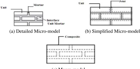
The following modeling strategies can be adopted depending on the level of accuracy, simplicity desired and application field (1) Detailed micro modeling: Units and mortar joints are represented by continuum elements whereas the unit brick interface is represented by discontinues elements. (2)Simplified Micro modeling: Expanded units are represented by continuum elements whereas the behavior of the mortar joints and unit-mortar interface is lumped in discontinuous elements. (3) Macro-modeling units, mortar and unit-mortar interface are smeared out in the continuum. The present work uses detailed macro modeling. The main advantage of detailed macro modeling is that, it is convenient for the modeling of whole structure, because the number of elements required can be huge, and consequently the cost of calculation time can be reduced tremendously. Memory requirements are also low.
(a) Detailed Micro-model (b) Simplified Micro-model
www.ijiset.com Fig.2 Infill Models
2.3 Material Property
Table 1. Material Property
Description
Young’s
Modulus
(kN/mm2)
Poisson’s
Ratio
Density
(kg/m3)
Concrete 24 0.2 2400
Infill wall 4 0.17 1800
2.4 Models
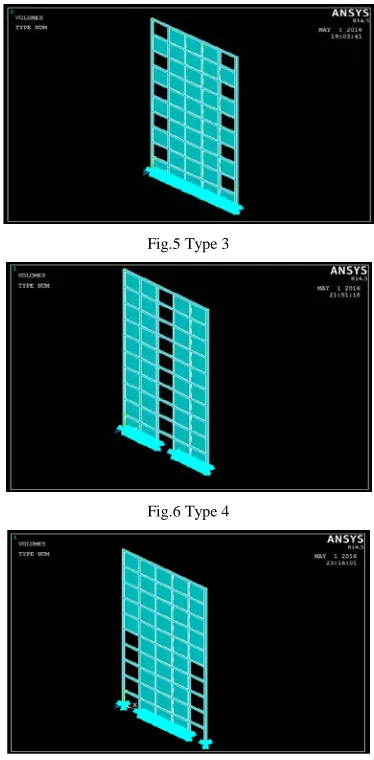
For studying the effect of distribution of infill on the dynamic behavior of the building, a ten storey frame with 80% infill is considered. By keeping all the parameters constant except the distribution of infill, 5 models are considered with the possible distribution of infills.
Fig .3 Type 1
Fig. 4 Type 2
That are Type 1 (resembles to a frame in building with first two stories are for parking ), Type 2 (resembles to a frame in building with top two stories are for auditorium purpose ), Type 3 (resembles to a frame in a duplex flat with balconies in alternative floor ), Type 4 (resembles to a frame in a building with central passage) and Type5 (resembles to a frame in a building with two passages at
the extreme ends up to the fifth floor). They are as shown below.
Fig.5 Type 3
Fig.6 Type 4
Fig.7 Type 5
3. Analysis and Results
www.ijiset.com
Fig.8 Deflection of Type 1 model due to Earthquake in X - direction
Fig.9 Deflection of Type 2 model due to Earthquake in X – direction
Fig.10 Deflection of Type 3 model due to Earthquake in X - direction
Fig.11 Deflection of Type 4 model due to Earthquake in X - direction
Fig.12 Deflection of Type 5 model due to Earthquake in X - direction
Fig.13 Deflection of Type 1 model due to Earthquake in Z - direction
Fig.14 Deflection of Type 2 model due to Earthquake in Z - direction
0 0.0050.01 0.0150.02 0.025
Ty
pe
1
Ty
pe
2
Ty
pe
3
Ty
pe
4
Ty
pe
5
D
is
p
la
ce
me
n
t (
m)
Infill Distribution
Earthquake in X- direction
Fig.15 Variation of Deflection due to Earthquake in X- direction
www.ijiset.com
1.2 1.25 1.3 1.351.4
T
yp
e 1
T
yp
e 2
T
yp
e 3
T
yp
e 4
T
yp
e 5
Di
spl
a
c
e
m
e
nt
(
m
)
Infill Distribution
Earthquake in Z-direction
Fig.16 Variation of Deflection due to Earthquake in Z- direction
The shear stress variation of the five models are studied both in the x and z earthquake directions. From that it is clear that the critical case is the earthquake in z- direction because the shear stresses are maximum at that stage. Some shear stress patterns are shown in Fig15 and Fig16.
0
10000
Type 1
Type 2
Type 3
Type 4
Type 5
Shear Stress (kN/m2)
In
fill Dis
tr
ib
u
tio
n
Eathquake i
X-direction
Earthquake
Z-direction
Fig.17 Comparison of Shear Stress due to Earthquake in X and Z
direction
Fig.18 Shear Stress Diagram of Type 4 model
Fig.19 Shear Stress Diagram of Type 3 model
Fig.20 Shear Stress Diagram of Type 5 model
Von mises stress of frames with five different infill configurations are studied during the earthquakes in two directions. The comparison between them are shown in Fig17. The main difference between this two type earthquake conditions are shown in Fig 18 and19 respectively.
0 10000 20000 30000 40000
V
o
n
Mi
se
s
S
tr
ess
(k
N/
m
2
)
Infill Distibution
Earthquake in X- direction Earthquake in Z- direction
www.ijiset.com Fig.22 Von Mises Stress Diagram of Type 3 model due to Earthquake in
X- direction
Fig.23 Von Mises Stress Diagram of Type 3 model due to Earthquake in Z - direction
3. Conclusions
From the analysis, it is clear that the shorter base of the building is always act as the weaker direction and longer base is act as the stronger direction during earthquakes. In the present model, shorter direction is in the z-direction. So the displacement and stresses are gives larger values in this direction.
Also from the stress diagrams, it is clear that the infills play a crucial role in the load transfer. Because the stress patterns reveals that the infill act as a bracing systems in the bare frames. Also the variation in distribution of infills shows a remarkable variation in their stress and displacement values. So it is very important to consider the infill distribution in design for knowing the correct behavior of structure during earthquake.
Also in most cases, the bottom soft storey structures are the critical case. So it is necessary to consider the weak ground in the analysis stage of such type of building design. If the earthquake is acted along the weaker direction, then the maximum von mises stresses are concentrated at the bottom columns. This leads to the entire collapse (pancake) of the structure.
If the earthquake are acted along the stronger direction, then the maximum von mises stresses are concentrated at the infill discontinuity points. This will leads to the bending collapse of the structure.
Acknowledgments
First of all, I would like to thank Almighty God. Next, I express regards to my family for their constant encouragement. I would like to extend my gratitude to all the staff members, Department of Civil Engineering, MBITS Nellimattom for their direct and indirect support during this work. I would also like to thank my friends for their valuable co-operation and suggestions.
References
[1] Y.P. Yuen, J.S. Kuang., Nonlinear seismic responses and lateral force transfer mechanisms of RC frames with different infill configurations, Engineering Structures 91, 125–140, 2015.
[2] Naveen Kumar B.Set al., Time Period Analysis of Reinforced Concrete Building with and Without Influence of Steel Bracings , International Journal of Modern Chemistry and Applied Science, 2015.
[3] Made Sukrawa, Earthquake response of RC infilled frame with wall openings in low-rise hotel buildings, Procedia Engineering 125 , 933 – 939, 2015.
[4] Cinitha.A, Umesha.P.K., A rational approach for fundamental period of low and medium rise steel building frames, International Journal of Modern Engineering Research (IJMER), Vol. 2, Issue. 5, Sep.- Oct. 2012. [5] G. Uva et al., Appraisal of masonry infill walls effect in the
seismic response of RC framed buildings: A case study, Engineering Structures 34, 514–526, 2012.
[6] Jaime Andrés Campbell Barraza., Numerical model for nonlinear analysis of masonry walls, RWTH, July 2012.
[7] Sirajuddin M, Narayanan Sambu Potty and Sunil J., Non Linear Seismic Analysis of Masonry Structures, Journal of Design and Built Environment, Vol. 9, pp. 1–16, December 2011.
[8] IS 1893 (Part1) : 2002.
1Ebitta Joy
M Tech-2016 B Tech-2013
Structural Engineer, Felix Structural Consultancy, Kothamangalam-2014
Assistant Professor, ILMCET, Methala
2Divya Sasi
M Tech-2013 B Tech -2011