Volume 2010, Article ID 148303,13pages doi:10.1155/2010/148303
Research Article
Traffic Flow Condition Classification for Short Sections Using
Single Microwave Sensor
Muhammed G. Cinsdikici
1and Kemal Memis¸
21International Computer Institute, Ege University, 35100 Bornova, Turkey
2Traffic Systems Department, Aselsan Mil.Electrnoics Company, ASELSAN Inc., 10016 sok.No. 16, A.O.S.B, C¸ i˘gli, 35620 ˙Izmir, Turkey
Correspondence should be addressed to Muhammed G. Cinsdikici,[email protected]
Received 19 October 2009; Accepted 2 September 2010
Academic Editor: Hossein Pishro-Nik
Copyright © 2010 M. G. Cinsdikici and K. Memis¸. This is an open access article distributed under the Creative Commons Attribution License, which permits unrestricted use, distribution, and reproduction in any medium, provided the original work is properly cited.
Daily observed traffic flow can show different characteristics varying with the times of the day. They are caused by traffic incidents such as accidents, disabled cars, construction activities and other unusual events. Three different major traffic conditions can be occurred: “Flow,” “Dense” and “Congested”. Objective of this research is to identify the current traffic condition by examining the traffic measurement parameters. The earlier researches have dealt only with speed and volume by ignoring occupancy. In our study, the occupancy is another important parameter of classification. The previous works have used multiple sensors to classify traffic condition whereas our work uses only single microwave sensor. We have extended Multiple Linear Regression classification with our new approach of Estimating with Error Prediction. We present novel algorithms of Multiclassification with One-Against-All Method and Multiclassification with Binary Comparison for multiple SVM architecture. Finaly, a non-linear model of backpropagation neural network is introduced for classification. This combination has not been reported on previous studies. Training data are obtained from the Corsim based microscopic traffic simulator TSIS 5.1. All performances are compared using this data set. Our methods are currently installed and running at traffic management center of 2.Ring Road in Istanbul.
1. Introduction
Traffic flow characteristic shows dynamical change at dif-ferent time periods of the day. Many traffic incidents such as accidents, disabled cars, construction activities, high demands on traffic, and other unusual events cause this change. For dealing with these unstable traffic problems, traffic conditions should be clarified. Mainly there exist three different major traffic conditions: “Flow Traffic,” “Dense Traffic,” and “Congested Traffic”. Clarification of them req-uires careful/detailed examination of the flow parameters of
speed,volume, and occupancy (SVO).
Accurate interpretation ofSVOsupports traffic manage-ment centers to make proper decision on directing the traffic to the less intensive roads. Hence, the response time for intervention in an incident will be reduced.
Measurement methods for obtainingSVOhave changed for the last 60 years of the span (i.e., especially the last 40 years with the rapid rise in the number of freeways). Indeed,
they are still changing [1]. Some of them are
(i) measurement at a point,
(ii) measurement over a short section (about 10 meters), (iii) measurement over a length of road (at least 0.5 km),
(iv) measurement with mobile observer in the traffic stream,
(v) measurement with multiple simultaneous mobile vehicles, as part of ITS (Intelligent Transportation Systems).
Although all measurement methods above producespeed
andvolumeofSVO,the only method producingoccupancy
(i.e., the percentage of unit time that the detection zone of the instrument is occupied by vehicles) is the measurement over a short section [1].
ultrasonic, and analog/digital camera technologies [1]. Since the quick and effortless installation is possible only on IL technology, we have used Radio Transmissions Microwave Sensor-based (RTMS) IL detector. We have collected SVO
parameter values at different times of day by using RTMS-IL. The collectedSVO data is analyzed through our three distinct novel approaches to classify traffic flow as “Flow”, “Dense”, or “Congested”. These approaches are estimating error prediction for multiple linear regression analysis, two improved variants of support vector machines (SVM), and backpropagation neural network. First two methods are linear classifiers, whereas NN is non-linear.
InSection 2, the contributions of our paper will be given in the related works. Then, background is presented. In the
Section 4, all details about the proposed study are going to be given.Section 5summarizes experimental results. Finally, conclusion is given.
2. Related Works
Flow theory has been tried to analyze traffic through the
speed,volume,and thevehicular concentrationparameters. Temporal vehicular concentration named asoccupancy
can be measured only over a short section (i.e., shorter than the minimum vehicle length). So, this parameter becomes unmeaning for long section measurements.
Density as an alternative vehicular concentration has been a part of traffic measurement since 1930’s. It depicts the number of vehicles over a long section (i.e., one mile or kilometer) in contrast to occupancy.
Although vehicular concentration encompasses both
density andoccupancy parameters, indeed, it would be fair to say that the majority opinion is in favor of usingdensity
during the evolution of traffic flow theory.
However, a minority view has intended to useoccupancy
in theoretical works. Although there are well-defined facts put forward by the majority for the continued use ofdensity, the minority also propounds major reasons for making more use of occupancy. The most crucial reason among them can be given as density (i.e., vehicles per length of road) ignores the effects of vehicle length and traffic composition.
Occupancy, on the other hand, is directly affected by both of these variables and therefore gives a more reliable indicator of the amount of a road being used by vehicles.
First mathematical model-based onspeed, volume,and
density variables had been developed by Greenshild in mid 1930s [2] using the aerial photographs. In his work, relationship betweenspeedanddensityis introduced relying on simple linear regression approach.
After World War II, with the tremendous increase in use of automobiles and the expansion of the highway system, there was also a surge in the study of traffic characteristics and the development of traffic flow theories. In 1950’s, theoretical developments based on a variety of approaches, such as car-following, traffic wave theory (hydrodynamic analogy), and queuing theory has emerged. Some of the seminal works of that period include the works by Reuschel (1950) [3–5], Wardrop (1952) [6], Pipes (1953) [7], Lighthill and Whitham (1955) [8], Newell (1955) [9],
Webster (1957) [10], Edie and Foote (1958) [11], Chan-dler et al. (1958) [12], and other papers by Herman et al.
Reuschel and Pipes offered a microscopic traffic model that identifies the linear dependency between thespeed of a vehicle and the distance between the vehicles in a single lane. The models described by Reuschel and Pipes were reasonable in concept, but no experimental verification of their conclusions was pursued for many years [13].
Wardrop’s theory was based on two major principles. The first one was stating that travel times between the same origin and destination pairs for any used routes are less than or equal to the travel times for all unused routes. This is referenced as Dynamic User Equilibrium (DUE) in the literature and used for large-scale networks. Diverting traffic with DUE is inefficient and difficult-to-implement system optimum (i.e., min. average travel time) [14]. The second one aims at minimizing both the total travel times and average travel times for all assigned routes for all drivers on the whole network. However, individual choice of drivers was by no means guaranteed to satisfy this principle and in most cases did not [13].
A few years later, Lighthill and Whitham (L-W) together set out the first comprehensive theory of kinematic waves. In L-W traffic model, there exists correlation between traffic flow (cars/hour) and traffic density (cars/mile) [8]. Propagation of shock waves, generated by traffic transitions from one steady state to another, was also determined by L-W model. Nevertheless, this model was viable only for describing the density changes. Unfortunately, the model produces larger densities exceeding the possible maximum vehicle density.
Greenberg improved the existing mathematical models by adding the nonlinearity into the model structure [15]. He treats the traffic stream as a continuous fluid and derives the relations betweenspeed,density, andflowby fluid dynamics. The distinction of free (i.e., non-congested) and con-gested flow on thespeed-densitymodel was carried out by Eddie [16] and Underwood [17] and was investigated in an important empirical test by Drake et al. [18].
Athol [19] suggested using the occupancy rather than the density for the flow-concentration works, however his suggestion became popular one decade later.
Speed, flow, and occupancy (SFO) relationships have been studied at the free flow level by Hurdle and Datta [20], Persaud and Hurdle [21], F. L. Hall and L. M. Hall [22], Banks [23], Smith et al. [24], Hall et al. [25], and Wemple et al. [26]. Also,SFOhave been studied at congested flow level and by Hall and Montgomery [27], Zhou and Hall [28], and Banks [29,30].
In ITS, neural networks can be found on the areas like vehicle detection, road detection, and single loop vehicle type classification [32,33]. Rarely some work related with traffic flow control can be found and they are also not well defined [34].
All retrospective researches so far show the binary relationships between the traffic parameters such asflow rate
and occupancy (FR-O), flow rate and speed (FR-S), speed
and occupancy (S-O) at congested or flow levels. Traffic status is assessed according to these binary relationships or by inspecting only one parameter (like speed) rather than examining all of them.
The first contribution of this paper to the traffic studies is focusing on another major traffic flow level ignored in earlier researches called dense flow level. All the previous works studies congested and flow traffic levels.
The second contribution of the paper is that no one in the earlier works is based on “single sensor” (i.e., all of them used double sensor placed within some distance) with using
SVOtriplets (i.e., triple relations of traffic parameters). The third one is our new approach of “estimation with error prediction” for multiple-linear regression.
The fourth and most important one is our novel algorithms of “Multiclassification with One-Against-All” and “Multiclassification with Binary Comparison” as variants for support vector machine (SVM) classifier for the traffic flow model.
The final contribution is that none of the earlier works uses neural network model to classify the traffic control by short section with single ILD.
3. Background
One of the short section detectors, RTMS, is capable of producing some kind of traffic parameters periodically for each lane on the freeway. These parameters are volume, speed, and occupancy.
(i) Volume shows the count of total vehicles passed through this short section for one period.
(ii) Speed shows the average speed of total cars passed through this short section for one period.
(iii) Occupancy shows the sum of the time; vehicles occupy the short section divided by one period time.
3.1. Linear Multiple Regression Analysis Method as a Classifier.
The objective of linear multiple regression analysis (LMRA) is to define which of the independent variables are important on predicting the model [35]. Multiple regression analysis provides a predictive equation
Y=a+β1x1+β2x2+· · ·+βnxn, (1)
where,ais interception constant, βi(i=1, 2,...,n)are standard-ized partial regression coefficients (reflecting the relative impact on the criterion variable).xi(i=1, 2,...,n)are the metric scores (i.e., interval or ratio data) of different independent variables.Y is the single dependent variable structuring the
X2
X1
Optimal hyperplane
Maximum margin
Figure1: Maximum margin of optimal hyperplane.
model. Equation (1) actually symbolizes a linear hyper plane. The purpose of the LMRA classifier is to minimize the energy functionEfor each data point, defined by LMS as in (2). The parametersaandβi(i=1, 2,...,n) are obtained from solving the partial derivatives of
E= yp−a+β1x1p+β2x2p+· · ·+βnxnp 2
. (2)
for given data.
3.2. Support Vector Machine as a Classifier. Another inno-vative supervised pattern classifier technique SVM was first proposed by Vapnik in 1995 [36]. The formulation applied by SVM embodies the Structural Risk Minimization (SRM) principle, which has been shown to be superior to traditional Empirical Risk Minimization (ERM) principle [37]. While SRM minimizes an upper bound on the expected risk, ERM minimizes the error on the training data [38]. It is the difference which equips SVM with a greater ability to generalize, which is the goal in statistical learning. SVMs were developed to solve the classification problem (i.e., data must belong to either Class 1(+1) or Class 2(−1)) but recently they have been extended to the domain of regression problems [39].
The decision function in (3) determines the classes of all input vectors (x = xi
m) [wherei is the input andmis the
tuple indexes].φis fixed feature-space transformation,Wis mdimensional weights, andbis bias term [40]:
D(x)=WTφ(x) +b. (3)
If there are multiple solutions, we should find the smallest generalization error. So, “margin” (i.e., smallest distance between decision boundary and any of the samples) should be found through [controlling the separability] [41]:
minWTx+b=1. (4)
Although there are infinite number of solutions to separate hyperplanes, by maximizing the margin, Figure 1
Structure Description of decision regions
Exclusive or problem
Classes with meshed regions
General region shapes
Most general region shapes
Single layer
Two-layer
Three-layer
Half plane bounded by
hyperplane
Arbitrary (complexity limited by # of hidden
units)
Arbitrary (complexity limited by # of hidden
units)
Structure Description of
decision regions
Exclusive or problem
Classes with meshed regions
General region shapes
Most general region shapes
Single layaa er
Tw T T o-layaa er
Three-layaa er
Half plane bounded by hy h h perplane
Arbitrary (complexity limited by # of hidden
units)
Arbitrary (complexity limited by # of hidden
units)
Figure2: Classification interpretation of ANN model selecyion [51].
The margin is given by the perpendicular distance to the closest pointxi from the data set and we wish to optimize
the parametersW andbin order to maximize this distance (using target ti). Thus the maximum margin solution is
found by solving
argmax
W,b
1
W
min
i
ti
WTφ(x) +b . (5)
The dominating approach for solving multiclass prob-lems using SVM has been based on reducing single multi class problem into multiple binary problems. For instance, a common method is to build a set of binary classifiers where each classifier distinguishes between one of the labels to the rest. This approach is a special case of using output codes for solving multi class problems [42]. However, while multi class learning using output codes provides a simple and powerful framework it cannot capture correlations between the different classes since it breaks a multi class problem into multiple independent binary problems [43].
The idea of casting multi class problems as a single constrained optimization with a quadratic objective function was introduced by Vapnik [44] and Watkins [45]. These attempts to extend the binary case are achieved by adding constraints for every class and thus the size of the quadratic optimization is proportional to the number of categories in the classification problems. The result is often a homoge-neous quadratic problem which is hard to solve and difficult to store. The idea of breaking constrained optimization prob-lem into smaller probprob-lems was extended by Joachims [46]. Multiple class problems were then discussed by Sch¨olkopf [47]. Today’s panorama of SVM is well summarized by Cristianini [48] and more completely by Sch¨olkopf and Smola [49].
3.3. Backpropagation Neural Network as a Classifier. Artificial neural networks (ANN) are used to serve two important functions as pattern classifiers and as nonlinear adaptive
V3,4
W4,2 W1,1 V1,1
Input
Hidden
X1
X2
X3
Z1
Z2
Z3
Z4
Y1
Y1
Output
Figure3: Simple Three-layered Neural Network Structure (3-4-2).
filters. Figure 2 gives a brief overview about the ANN architecture for proper pattern classification [50,51]. Since the data is not guaranteed to be linearly separable (i.e., overlapped), three-layered Backpropagation NN (BPNN) architecture is chosen in this paper as classifier. This type of architecture does not need any prior knowledge about data (i.e., exemplar pattern initialization). Since there is no need for distribution of the data (for fault-tolerance), asyn-chronous update in weights and self-classification, BPNN is suitable as supervised classifier [32,50]. InFigure 3, simple three-layered BPNN is indicated.
0 10
20
0 2 4 6 8 10 12 0 20 40 60 80 100 120
Volume
Speed
Oc
cupancy
Congested traffic
Figure4: An example simulator data for Congested traffic.
0 20
40 60
80 100
0 50
100 0 5 10 15 20 25
Volum e
Flow traffic
Speed
Oc
cupancy
Figure5: An example simulator data for Flow traffic.
about the formulation and theory about these learning methods.
4. Proposed Method
4.1. Data. For each traffic condition, different values and types of data can be acquired through the FHWA’s (Federal Highway Agency) TSIS 5.1 software (i.e., a CORSIM-based microscopic traffic simulation tool). Differentiation of data is supplied by configuring simulation tool parameters such as distribution function of generated traffic, lane speeds, car distances, and incident creation intervals.
20 30
40 50
20 25
30 35 40 45 50 55 10 15 20 25 30 35 40 45 50
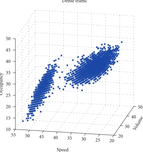
Volu me Dense traffic
Speed
Oc
cupancy
Figure6: An example simulator data for Dense traffic.
Each ILD sensors generatesspeed,volume,andoccupancy
parameters values for configurable one period of time (i.e., 60 seconds) for each lane on the freeway.
4.1.1. Congested Condition. Congested traffic condition can be observed by creating long-term incidents along the freeway. According to the number of lanes they occupy, incidents can be assorted. In our study, kinds of incident scenarios are created for four-lane freeway. The sensors are placed 100 feet upstream from the incident point. As seen inFigure 4occupancy reaches the maximum values, whereas bothspeedandvolumereach the minimum values.
4.1.2. Flow Condition. In order to generate the flow traffic condition, CORSIM’s average speed input is determined from high values (i.e., 90 km/h) and no incidents are created.
Figure 5illustrates the flow condition. It is clear from the figure that, when the speed is high and volumeis low, the
occupancy approximately reaches to zero. Under the low
speedand high volume conditions, occupancy rises but never reaches to the maximum value.
4.1.3. Dense Condition. Dense traffic condition can be iden-tified by generating lowspeedvalues, short-term incidents, and decreased distances between the cars in traffic. This condition is observed between the flow and congested conditions. As seen inFigure 6theoccupancynever reaches to min or max values.
0 50
100 150 0
20 40
60 80 0
20 40 60 80 100
Speed 98.2–8.5x-2.5y
Volume
Oc
cupancy
Figure7: Regression plane (red) for Congested traffic.
flow traffic condition or not. On the contrary, occupancy
goes to maximum value whenspeedapproximates to zero in congested traffic flow condition.
It is also obvious that, until the volume reaches its maximum,occupancyis also increasing. After the maximum, thevolumeis going to be monotonically decreasing whereas
occupancyis still increasing.
Under these circumstances, in flow traffic condition more
volume leads to more occupancy. However, in congested traffic flow, the lessvolumeobserved leads to moreoccupancy. According to the facts mentioned above, occupancy is dependent both onspeedandvolume.
Occupancy=a+β1∗Volume+β2∗Speed+Error. (6)
Equation (6) is not viable in real world affairs. Once the traffic seems to be in congested, both speed, and
volume can show the zero, althoughoccupancy approaches to maximum. Unless the vehicles exist along the freeway (i.e., flow condition),speed,volume,and also theoccupancy
indicate zero. A linear dependency of SVOfor each traffic condition with respect to the discrepancy are modified from (6) as in (7). For each flow conditiona,β1, andβ2parameters are different,
Occupancycondition=a+β1∗Volume+β2∗Speed+Error.
(7)
4.2.1. Regression Planes. Using the CORSIM data,α,β1, and β2values for each traffic condition are calculated using LMS (Least Mean Squares) method. The obtained results can be tracked through following subtitles.
0 10 20 30 40 50 60
0 50 100 1500
10 20 30 40 50 60 70
70 80
90 100
Volume
0.05 + 0.3x−0.004y
Sp eed
Oc
cupancy
Figure8: Regression plane for Flow traffic.
(a) Congested condition. The plane evaluated for congested traffic is depicted inFigure 7and its equation is in
Occupancycongested=98, 02−8, 5∗Volume−2, 5∗Speed. (8)
Through the crosschecking (8), it can easily be seen that
occupancy reaches max (98.2) when the speed andvolume
are marked as zero. This verifies the expectations of the real traffic condition.
(b) Flow Condition. Figure 8shows the plane obtained from
the flow traffic. Its equation is defined as
Occupancyflow=0, 05 + 0, 3∗Volume−0, 004∗Speed. (9)
In real traffic, if no car is detected on the freeway during the time period, detectors will produce theoccupancy as 0 whereasspeedandvolumealso share the same value. Through the crosschecking (9), it can easily be seen that occupancy
reaches min (0.05) when thespeedandvolume are marked as zero. This verifies the expectations of the real traffic condition.
(c) Dense Condition. Figure 9depicts the dense traffic flow
condition’s regression plane. Linear equation of the plane can be defined as
Occupancydense=34.5 + 0, 58∗Volume−0, 7∗Speed.
(10)
(d) Combined Data and Regression Planes. Data and regres-sion planes of all traffic conditions are shown inFigure 10.
Three different methods are applied, respectively, for classification of traffic conditions using linear regression.
0 20
40 60
0 50 100 150
Volum e
34.5 + 0.58x−0.7y
Speed
Oc
cupancy
0 10 20 30 40 50 60 70 80 90 100
Figure9: Regression plane for Dense traffic.
points and each plane. The result (i.e., nearest plane) supplies us to infer the class (status) of current traffic.
From (8), we can obtain (11) for congested traffic as
0=98, 02+8, 5∗Volume−2, 5∗Speed−Occupancycongested, dcongested
=98.02−8, 5∗Volume −2, 5∗Speed−Occupancy 8, 52+2, 52+12 .
(11)
From (9), we can obtain (12) for flow traffic as
0=0, 05+0, 3∗Volume−0, 004∗Speed−Occupancyflow; dflow
=0, 05−0, 3∗Volume −0, 004∗Speed−Occupancy 0, 32+0, 0042+12 .
(12)
From (10), we can obtain (13) for dense traffic as
0=34.5+0, 58∗Volume−0, 7∗Speed−Occupancydense, ddense
=34.5−0, 58∗Volume −0, 7∗Speed−Occupancy 0, 582+ 0, 72+ 12 .
(13)
(2) Estimating Occupancy without Error Prediction (EO). In EO, linear regression (6) is used and error is assumed as zero. Using this assumptionoccupancyestimator can be calculated for each simulated traffic condition (8), (9), (10) using the realspeedand realvolume. After acquiring these estimators, they are compared with the realoccupancy. The one nearest
0 10 20 30 40 50 60 70
0
50
100
150 0
20 40 60 80 100
Speed Volume
Oc
cupancy
Figure10: Composite regression planes of all traffic.
to real occupancy becomes the result of our traffic flow condition.
(3) Estimating Occupancy with Error Prediction (EOwEP):
Another method for finding the traffic flow class is extended version of EO. This method calculatesoccupancyestimators by adding the predicted error values.
EOwEP depends on the training data values and their residuals. Nearest point is found by measuring L2 distance between real traffic data point and CORSIM simulated data points from each traffic condition. The residual of the found point is assumed to approximate our error. As a result,
occupancy estimator for that condition can be determined. So the obtained equation as
Occupancycongested=98, 02 + 8, 5∗Volume−2, 5
∗Speed+resi,
(14)
whereiis the nearest point, found by (15), to the real data point among the congested training data points
Min(Voli−Vol)2+
Speedi−Speed 2
+ (Occi−Occ)2 .
(15)
4.3. Support Vector Machines. As mentioned in background, SVM is generally applied to binary classification problems. Since the addressed problem is mapping the input data into one of three flow conditions, SVM can be seen inapplicable at first. However, without changing its calculation style, SVM can also be used in multiclassification problems. The idea lays behind multi classification is just using more than one SVM and classifing the data according to the outputs of multiple SVMs. We use our two novel approaches for Multiple SVM.
Multiclassification with One-Against-All Method (OAAM).
BPNN Algorithm;
(i) Initialize weights (vi,j, wj,k) with small random values (ii) Broadcast the input data to the input layerxi Feed-forward phase is starting here;
(i) Calculate the hidden layer unit signals (“f” is sigmoid function in our work)
zj in= n
i=1xivi j zj=f(zj in)=
2 1 +e−zj in −1 (ii) Calculate the output unit signal
yk in= p
j=1zjwjk
yk= f(yk in)=1 +2 e−yk in −1 Backpropagation phase is starting here;
(i) Calculate the residual. By using expected value for output signal (tk).
δk=(tk−yk)∗f(yk in)=(tk−yk)∗
1
2[1 +f(yki n)][1−f(yk in)]
Δwjk=αδkzj
whereαis learning rate. In the learning phase,Δwjk is updated according to learning rule. (ii) Then calculate reflectance of the residuals and propagate it to the input weights.
δj = m
k=1δkwjk∗f
(z
j in) Δvi j=αδjxi
(iii) All weights are updated with learning rule (i.e., gdm/scg). wjk(new)=wjk(old) +Δwjk
vi j(new)=vi j(old) +Δvi j
(iv) Test the stopping condition (i.e., reaching to “goal”; predefined Mse —mean square error- of the total residuals)
Algorithm1
[“+1” (Class 1), “−1” (Class 2)] indicates if the input data belongs to this SVM or not.
For modeling OAAM, data is acquired from TSIS 5.1. Decision is made through. “KKT (Karush-Khun-Tucker method for minimizing Quadratic Problem solution for SVM) [45] ”.
min
1 2W
2
. (16)
(a) Congested SVM (C-SVM). In the training, C-SVM target is trained with “+1” whereas the other SVM targets are trained with “−1”. Plane for C-SVM can be shown in
Figure 11. Its equation is
Dvol, spd, occ= −0.1235∗vol−0.0443∗spd+ 0.1052
∗occ−0.9996.
(17)
(b) Dense SVM (D-SVM). In the training, D-SVM target is trained with “+1” whereas the other SVM targets are trained with “−1”. Plane for D-SVM can be shown inFigure 12. Its equation is
Dvol, spd, occ=2.6577∗vol−1.7462∗spd−0.2456
∗occ−0.9998.
(18)
(c) Flow SVM (F-SVM). In the training, F-SVM target is trained with “+1” whereas the other SVM targets are trained with “−1”. Plane for F-SVM can be shown inFigure 13. Its equation is in (19);
Dvol,spd,occ=0.0105∗vol+ 0.0788∗spd−0.3218
∗occ+ 1.0003.
(19)
After training is done, each member of Multiple-SVMs has its own linear planes for OAAM. In order to get the correct class of the queried data is just easy as to look at the responses of each SVMs. The “+1” response of the SVM clarifies the class of the data. For instance if F-SVM’s response is “+1” (i.e., the others are expected as “−1”) then the class of the data belongs to flow traffic.
However, this is not sufficient alone. Following cases must be taken into account and supplemented approaches must be applied in these conditions.
(i) If at least two SVMs produce output “+1”, then the one with the longest L2 distance from data point to its own SVM plane can be picked out. Since the furthest distance from the data point to plane exposes the stricter and more accurate data for current traffic flow condition, we choose the furthest one.
0 10
20 30
40 50
60
70 0 50
100
150 0
20 40 60 80 100
Speed
9.5019 + 1.1739x+ 0.4211y
Vo
lume
Oc
cupancy
Figure11: Congested Traffic Plane for C-SVM of OAAM.
0 10
20 30
40 50
60 70
0 50 100
150 0 10 20 30 40 50 60 70 80 90 100
Volume
−4.0708 + 10.8212x−7.1099y
Speed
Oc
cupancy
Figure12: Dense Traffic Plane for D-SVM of OAAM.
Producing output “–1” implies that the data does not belong to the current SVM’s traffic condition. Since, the shortest distance from data point to SVM plane is the nearest one to “+1” (Class 1), we can pick this SVM out as our desired class.
Multiclassification with Binary Comparison (BC). Our other novel approach applied to classify our data is again composed of three SVMs. However, it can be distinguished from the OAAM method by its architecture. In BC method, each SVM is responsible for the following binary combinations, respectively; (Congested, Dense), (Congested, Flow), and (Flow, Dense). This multi classification method depends on basic voting principle. There exist three candidates (i.e., Congested, Flow, and Dense traffic conditions) and three voters (each SVM). The one among the candidates wins the election if it gets the most votes from voters.
020 4060
0 50
100 150
0 10 20 30 40 50 60 70 80 90 100
Volume Speed
3.1084 + 0.0326xx+ 0.2448y
Oc
cupancy
Figure13: Flow Traffic Plane for F-SVM of OAAM.
(a) Congested-Dense (CD-SVM). In the training, CD-SVM target “+1” indicates that data belongs to Class 1 (i.e., congested traffic). The other alternative of “−1” indicates that the data belongs to Class 2 (i.e., dense traffic).
So the voter gives its vote to Congested candidate if its output equals “+1”. In adverse condition, it gives to Dense candidate.Figure 14shows the decision plane for CD-SVM. The plane equation is
Dvol, spd, occ= −0.0642∗vol−0.0440∗spd−0.0041
∗occ+ 1.8692.
(20)
(b) Congested-Flow SVM (CF-SVM). In the training, CF-SVM target “+1” indicates that data belongs to congested traffic. The other alternative of “−1” indicates that the data belongs to flow traffic.Figure 15shows the decision plane for CF-SVM. The plane equation is
Dvol, spd, occ= −0.0044∗vol−0.0160∗spd+ 0.0711
∗occ−0.9998.
(21)
(c) Flow-Dense SVM (FD-SVM). In the training, FD-SVM target “+1” indicates that data belongs to flow traffic. The other alternative of “−1” indicates that the data belongs to dense traffic. Figure 16 shows the decision plane for FD-SVM. The plane equation is
Dvol, spd, occ=0.0105∗vol+ 0.0788∗spd−0.3218
∗occ+1.0003.
(22)
0 20
40 60
0 50 100
150 0
10 20 30 40 50 60 70 80 90 100
Speed
455.9024−15.6585x−10.7317y
Volume
Oc
cupancy
Figure14: Plane of CD-SVM for BC.
0
50 0 50
100 150
0 10 20 30 40 50 60 70 80 90 100
Volume Speed
14.0618 + 0.0618x+ 0.2250y
Oc
cupancy
Figure15: Plane of CF-SVM for BC.
give us the most accurate class for that data point. Then the SVM with the longest distance will choose the leader class.
Backpropagation Neural Network Architectures . The network architecture in our work is selected as three-layered back-propagation neural network (BPNN). three groups of data are used as input. The first group is fed into the network as training data set. The next one is used as verification data set. The last one is used as query set (i.e., test set) to measure the classification performance of the neural net.Training data set is obtained from TSIS 5.1 simulator. This data is verified through the verification set also gathered from the simulator. The test set is gathered from single sensor planted on the 2.Ring road in Istanbul. Test set indicates real data. Our model is trained and verified through the simulated data and tested with real traffic information.In the learning phase we have used gradient descent with momentum (Gdm) update
50 0 50
100 150
0 10 20 30 40 50 60 70 80 90 100
Volume Speed
3.1084 + 0.0326xx+ 0.2448y
Oc
cupancy
Figure16: Plane of FD-SVM for BC.
function in (23) (i.e., learning rule). This base rule is used for all architectures
wjk(t+ 1)=wjk(t) +αδkzj+μ
wjk(t)−wjk(t−1) ,
vi j(t+ 1)=vi j(t) +αδjxi+μ
vi j(t)−vi j(t−1) .
(23)
In the learning phase, we have used the algorithms of only Gdm, Levenberg-Maquardt with Gdm and Scaled Conjugate Gradient with Gdm [52]. Matlab 7.6.0 (Rev.2008a) Neural Network Toolbox where our related work algorithms and learning rules are ready is used.
We have used default max iteration as 1000, Mse goal value as 10−4, and verification iteration count as 6. The network architecture is performed as three-layered models of 3-10-3, 3-20-3, and 3-50-3. Since one hidden layer usage is almost identical with two hidden layered architecture, we prefer to use single hidden layer model. For the connec-tions lying between Input/Hidden Layers are trained with LogSig or PureLin activation functions. LogSig activation function normalized the input and applies Sigmoid. Pure Linear activation function transfers input to hidden.We give the performance analysis of our neural net architectures in Table 1. Gray labeled values are average performances obtained from 100 runs of neural net models. According to the average performances, our 3-20-3 backpropagation model gives the best result for classification.
5. Experimental Work
Table1: Backpropagation Neural Net Performances.
GDM LM SCG
LogSig-PurLin PurLin-PurLin LogSig-PurLin PurLin-PurLin LogSig-PurLin PurLin-PurLin
BackPrp 3-10-3
Cong 100 100 0.9604 0.9472 100 0.4073 Dense 0.5733 0.5612 0.5134 0.5671 0 0
Flow 0.9502 0.9189 0.9210 0.9470 0 0.062 Total (Rate/Iteration) 0.9678/1000 0.9258/1000 0.9352/360 0.9170/5 0.0068/156 0.0615/15
BackPrp 3-20-3
Cong 0.6227 0.9472 100 0.9393 100 0.9393 Dense 0.6914 0.6878 0.4677 0.6778 0.8531 0.6725 Flow 0.9804 0.8950 0.7492 0.8967 0.9914 0.9468 Total (Rate/Iteration) 0.8785/1000 0.9192/1000 0.7367/168 0.9102/4 0.9794/301 0.9512/23
BackPrp 3-50-3
Cong 0.9721 0.9393 0.9732 0.9893 0.9789 0.9472 Dense 0.4552 0.6686 0.1256 0.6800 0.6318 0.6711 Flow 0.9571 0.9869 0.9899 0.9907 0.9879 0.9867 Total (Rate/Iteration) 0.9120/1000 0.9265/1000 0.9058/35 0.9803/3 0.9595/136 0.9512/16
Table2: Estimation Performance of Our Model for Each Traffic condition.
Method Flow Dense Congested Analytic Geometry 99% 84% 70%
Without Error Prediction 100% 78% 35%
Error Prediction 99% 24% 46%
SVM with One-Against-All Method 100% 46% 97%
SVM with Binary Comparison 100% 74% 100%
BackPrp NN-SCG (3-20-3) 99.14% 85.31% 100%
BackPrp NN-LM (3-50-3) 99.07% 68% 98.93%
BackPrp NN-GDM (3-10-3) 95.02% 57.33% 100%
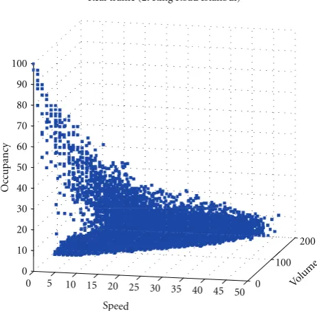
2.Ring Road. The measurements recorded at critical points on the road are transmitted periodically to the management center [53].
Occupancy, speed, and traffic volume measurements are both recorded in the database, and the traffic status according to these measurements is mapped to color codes and displayed on a large screen. Whenever any congested state or dense state occurs along the road, alarms with severity levels are generated and the operators are informed. Information regarding the traffic status is also displayed on LED-based Variable Message Signs (VMS) on the road.
During one day, data from 7 different microwave sensors is acquired every 60 seconds periodically. Occupancy, volume and speed measurements are shown in Figure 17. Videos from the traffic surveillance cameras, which are capable of watching the places that microwave sensors are installed, are also captured in order to synchronize them with the sensors measurements. Then, measurements are grouped as congested, dense and flow according to these videos. [We have used training data set of total size 18.000 x 3 (i.e., each traffic condition has balanced data subset size of 6000 x 3) and we have used testing data set of total size 55.000 x 3, and 3 indicatesSVO values]. These data sets are used to for the
Table 2.
0 100
200
0 5 10 15 20 25 30 35 40 45 50
0 10 20 30 40 50 60 70 80 90 100
Speed
Real traffic (2. Ring Road Istanbul)
Volume
Oc
cupancy
Figure17: Real Traffic data from 2.Ring Road in Istanbul (by 7 sensors).
6. Conclusion
screens. Once congested level is detected, it produces an alarm with high severity to inform the operators. Never-theless, dense level also creates alarm with lower severity. After verification of this assessment by operator, VMS can be supplied by messages to inform drivers about the road flow condition.
References
[1] F. L. Hall, “Traffic stream characteristics,” inUSA Transporta-tion Research Board. Traffic Flow Theory, A State of the Art Report, 1992.
[2] B. D. Greenshields, “A study of traffic capacity,” Highway Research Board Proceedings, vol. 14, pp. 448–477, 1935. [3] A. Reuschel, “Fahrzeugbewegungen in der Kolonne,”
Oesterre-ichisches Ingenieur, vol. 4, no. 3/4, pp. 193–215, 1950a. [4] A. Reuschel, “Fahrzeugbewegungen in der Kolonne bei
gle-ichformig beschleunigtem oder verzogertem, Leitfahrzeug,”
Zeitschrift des Oesterreichischen Ingenieurund Architekten-Vereines, vol. 95, no. 9, pp. 59–62, 1950.
[5] A. Reuschel, “Fahrzeugbewegungen in der Kolonne bei gle-ichformig beschleunigtem oder verzogertem, Leitfahrzeug,”
Zeitschrift des Oesterreichischen Ingenieurund Architekten-Vereines, vol. 97-98, no. 10, pp. 73–77, 1950.
[6] J. G. Wardrop, “Some theoretical aspects of road traffic research,”Proceedings Institute of Civil Engineers, Part II, vol. 1, pp. 325–378, 1952.
[7] L. A. Pipes, “An operational analysis of traffic dynamics,”
Journal of Applied Physics, vol. 24, no. 3, pp. 274–281, 1953. [8] M. J. Lighthill and G. B. Whitham, “On kinematic waves. II.
A theory of traffic flow on long crowded roads,”Proceedings of the Royal Society of London, pp. 317–345, 1955.
[9] G. F. Newell, “Mathematical models for freely-flowing high-way traffic,” Journal of the Operations Research Society of America, vol. 3, pp. 176–186, 1955.
[10] F. V. Webster, “Traffic signal settings,” Road Research Techni-cal, Road Research Laboratory, London, UK, 1958.
[11] L. C. Edie and R. S. Foote, “Traffic flow in tunnels,”Proceedings of Highway Research Board, vol. 37, pp. 334–344, 1958. [12] R. E. Chandler, R. Herman, and E. W. Montroll, “Traffic
dynamics: studies in car following,”Operations Research, vol. 6, pp. 165–184, 1958.
[13] D. C. Gazis, “The origins of traffic theory,” Operations Research, vol. 50, no. 1, pp. 69–77, 2002.
[14] J. R. Correa, A. S. Schulz, and N. E. Stier-Moses, “Selfish routing in capacitated networks,”Mathematics of Operations Research, vol. 29, no. 4, pp. 961–976, 2004.
[15] H. Greenberg, “An analysis of traffic flow,” Operations Research, vol. 7, pp. 79–85, 1959.
[16] L. C. Edie, “Car following and steady-state for non-congested traffic,”Operations Research, vol. 9, pp. 66–76, 1961.
[17] R. T. Underwood, “Speed, volume, and density relationships: quality and theory of traffic flow,” Yale Bureau of Highway Traffic, pp. 141–188, 1961.
[18] J. S. Drake, L. Schofer, and A. D. May, “A statistical analysis of speed density hypotheses,”Highway Research Record, vol. 154, pp. 53–87, 1967.
[19] P. Athol, “Interdependence of certain operational characteris-tics within a moving traffic stream,”Highway Research Record, vol. 72, pp. 58–87, 1965.
[20] V. F. Hurdle and P. K. Datta, “Speeds and flows on an urban freeway: some measurements and a hypothesis,” in
Transportation Research Record 905, pp. 127–137, TRB, NRC, Washington, DC, USA, 1983.
[21] B. N. Persaud and V. F. Hurdle, “Some new data that challenge some old ideas about speed-flow relationships,” in
Transportation Research Record, vol. 1194, pp. 191–198, TRB, NRC, Washington, DC, 1988.
[22] F. L. Hall and L. M. Hall, “Capacity and speed flow analysis of the Queue in Ontario,” inTransportation Research Record, vol. 1287, pp. 108–118, TRB, NRC, Washington, DC, USA, 1990. [23] J. H. Banks, “Freeway speed-flow concentration
relation-ships: more evidence and interpretations,” inTransportation Research Record, vol. 1225, pp. 53–60, TRB, NRC, Washington, DC, USA, 1989.
[24] W. S. Smith, F. L. Hall, and F. O. Montgomery, “Comparing the speed-flow relationship for motorways with new data from the M6,”Transportation Research Part A, vol. 30, no. 2, pp. 89–101, 1996.
[25] F. L. Hall, V. F. Hurdle, and J. H. Banks, “Synthesis of recent work on the nature of speed-flow and flow-occupancy (or density) relationships on freeways,” inTransportation Research Record, vol. 1365, pp. 12–18, TRB, NRC, Washington, DC, USA, 1992.
[26] E. A. Wemple, A. M. Morris, and A. D. May, “Freeway capacity and level of service concepts,” inProceedings of International Symposium on Highway Capacity, pp. 439–455, Karlsruhe, Germany, 1991.
[27] F. L. Hall and F. O. Montgomery, “Investigation of an alternative interpretation of the speed-flow relationship for U.K. motorways,”Traffic Engineering and Control, vol. 34, no. 9, pp. 420–425, 1993.
[28] M. Zhou and F. L. Hall, “Investigation of speed-flow relation-ship under congested conditions on a freeway,”Transportation Research Record, no. 1678, pp. 64–72, 1999.
[29] J. H. Banks, “Investigation of some characteristics of congested flow,”Transportation Research Record, no. 1678, pp. 128–134, 1999.
[30] J. H. Banks, “Review of empirical research on congested freeway flow,”Transportation Research Record, no. 1802, pp. 225–232, 2002.
[31] F. Yuan and R. L. Cheu, “Incident detection using support vector machines,”Transportation Research Part C, vol. 11, no. 3-4, pp. 309–328, 2003.
[32] C. Oh and S. G. Ritchie, “Recognizing vehicle classification information from blade sensor signature,”Pattern Recognition Letters, vol. 28, no. 9, pp. 1041–1049, 2007.
[33] R. Mussa, V. Kwigizile, and M. Selekwa, “Probabilistic neural networks application for vehicle classification,” Journal of Transportation Engineering, vol. 132, no. 4, pp. 293–302, 2006. [34] E. I. Vlahogianni, J. C. Golias, and M. G. Karlaftis, “Short-term traffic forecasting: overview of objectives and methods,”
Transport Reviews, vol. 24, no. 5, pp. 533–557, 2004. [35] http://www.isical.ac.in/∼ddroy/multistat.doc.
[36] V. N. Vapnik, The Nature of Statistical Learning Theory, Springer, New York, NY, USA, 1995.
[37] S. R. Gunn, M. Brown, and K. M. Bossley, “Network performance assessment for neurofuzzy data modeling,” in
Intelligent Data Analysis, vol. 1208 ofLecture Notes in Com-puter Science, pp. 313–323, 1997.
[39] V. Vapnik, S. Golowich, and A. Smola, “Support vector method for function approximation, regression estimation, and signal processing,” in Advances in Neural Information Processing Systems, vol. 9, pp. 281–287, MIT Press, Cambridge, Mass, USA, 1997.
[40] S. Abe,Support Vector Machines For Pattern Recognition, 2005. [41] C. Bishop, Pattern Recognition and Machine Learning,
Springer, New York, NY, USA, 2007.
[42] T. G. Dietterich and G. Bakiri, “Solving multiclass learning problems via error correcting output codes,” Journal of Artificial Intelligence Research, vol. 2, pp. 263–286, 1995. [43] K. Crammer and Y. Singer, “On the algorithmic
implementa-tion of multiClass kernel based vector machines,”Journal of Machine Learning Research, vol. 2, pp. 265–292, 2001. [44] V. N. Vapnik,Statistical Learning Theory, John Wiley & Sons,
New York, NY, USA, 1998.
[45] J. Weston and C. Watkins, “Support vector machines for multi-class pattern recognition,” in Proceedings of the 7th European Symposium on Artificial Neural Networks, 1999. [46] T. Joachims, “Making large-scale support vector machine
learning practical,” inAdvances in Kernel Methods—Support Vector Learning, B. Scholkopf, C. Burges, and A. Smola, Eds., MIT Press, 1998.
[47] B. Sch¨olkopf, Statistical Learning and Kernel Methods, Microsoft Research, 2000.
[48] N. Cristianini and J. S. Taylor, An Introduction to Support Vector Machines, and Other Kernel-Based Learning Methods, Cambridge University Press, Cambridge, UK, 2000.
[49] B. Sch¨olkopf and A. Smola,Learning with Kernels, MIT Press, Cambridge, Mass, USA, 2002.
[50] L. Fausett, Fundementals of Neural Networks: Architectures, Algorithms and Applications, Prentice-Hall, Upper Saddle River, NJ, USA, 1994.
[51] A. K. Jain, J. Mao, and K. M. Mohiuddin, “Artificial neural networks: a tutorial,”Computer, vol. 29, no. 3, pp. 31–44, 1996. [52] S. Haykin, Neural Networks: A Comprehensive Foundation,
Prentice-Hall, Upper Saddle River, NJ, USA, 1998.