DESIGN AND STUDY OF COMPACT SIZED PLANAR
INVERTED-F ANTENNA FOR Wi-MAX APPLICATION
1
Akanksha Khare
1
Electronics and Communication, Amity University, Noida, (India)
ABSTRACT
A Planar Inverted-F Antenna for WiMAX applications (3.3-3.8 GHz) has been presented in this paper. The proposed
structure has a dimension of 18 x 13 mm2 over the ground plane of size 100 x 50 mm2 which can easily be implanted
in the small space available within the mobile device. The proposed structure is having a impedance bandwidth
ranging from 3.198 GHz to 4.158 GHz covering WiMAX band. The antenna has a resonating frequency at 3.68 GHz
frequency. For getting the impedance bandwidth we are taking -6 dB as the reference return loss. The VSWR, input
impedance plot along with parametric study of some key parameters is presented. The radiation pattern and current
density plots of the antenna at 3.55 GHz and 3.68 GHz are also presented. The peak realized gain of the proposed
antenna varies from 4.15 dB to 5.2 dB in the desired operating band.
Keywords: Broad Frequency Bands, Impedance Bandwidth, Low-Profile Geometry, Planar Inverted-F
Antenna, Wimax,
1. INTRODUCTION
The rapid decrease in size of personal communication devices has lead to the need for more compact antennas. At
the same time, expansion of wireless systems has increased the applications for multi-functional antennas that
operate over broad frequency bands or multiple independent bands. In the past few years, new designs based on
planar inverted-F antennas (PIFA) have been used for handheld wireless devices because of its low-profile
geometry. The PIFA can be considered a direct extension of the inverted-F antenna that has the horizontal wire
radiating element replaced by a plate to increase its usable bandwidth. PIFA designs invoke the quarter-wavelength
operation. Additionally, the PIFA offers very high radiation efficiency and sufficient bandwidth in a compact
antenna.
Technique like use of reduced ground plane can to be employed to further increase the bandwidth [1], [2].
Multi-frequency capability with the antenna structure can be achieved by exciting various resonant modes using branched
In this paper a Planar Inverted-F Antenna for WiMAX applications (3.3-3.8 GHz) has been presented. The proposed
structure is having a impedance bandwidth ranging from 3.198 GHz to 4.158 GHz covering WiMAX band. The
antenna has a resonating frequency at 3.68 GHz frequency. Section 2 of the paper gives the details of the proposed
structure. Results and discussion is included in section 3 of this paper.
II ANTENNA DESIGN
The antenna structure is designed with Ansoft‟s HFSS. The antenna is designed at the top right corner of FR4
substrate of size Ws x Ls mm2. The antenna element is at a height of 4 mm above the substrate. At the bottom side
of the substrate, ground plane is placed. The antenna element is connected to the ground plane by a shorting strip of
width Wsh. The shorting strip is placed along the width of the substrate.
In order to get the resonance at the desired frequency, slot loading is done by an L-shaped slot in the antenna patch.
The antenna is fed by a coaxial cable at a place where impedance matching is proper. The top view and side view of
the proposed antenna structure is given in Fig. 1 and Fig. 2 respectively. Fig. 3 shows the detailed dimensions of the
antenna patch. The optimized parameters of the proposed structure are given in Table 1.
Ws Ls Ground Plane on 0.8 mm thick FR4 Substrate Antenna Element
Wp Lp Ws1 Ls1 Ls2 Ws2 L1 Lpr Wpr
Figure 1: Top View of the Proposed Antenna Structure. Figure 3: Detailed Dimensions of Antenna Patch.
H
Input Port Wsh
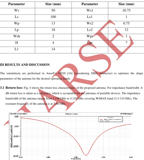
Table 2.1:
Optimized antenna dimensions
Parameter
Size (mm)
Parameter
Size (mm)
Ws
50
Ws1
10.75
Ls
100
Ls1
1
Wp
13
Ws2
0.75
Lp
18
Ls2
12
Wsh
2
Wpr
1
H
4
Lpr
7
L1
14
III RESULTS AND DISCUSSION
The simulations are performed in Ansoft‟s HFSS [16] (considering SMA connector) to optimize the shape
parameters of the antenna for the desired operating bands.
3.1
Return loss:
Fig. 4 shows the return loss characteristics of the proposed antenna. For impedance bandwidth -6 dB return loss is taken as a reference, which is acceptable for the antennas of portable devices. The impedancebandwidth of the antenna ranges from 3.198 GHz to 4.158 GHz covering WiMAX band (3.3-3.8 GHz). The
resonant frequency of the antenna is at 3.68 GHz.
3.2
Voltage Standing Wave Ratio (VSWR
):
The VSWR characteristics of the proposed antenna are presented in Fig. 5. It can be seen that for the operating frequency range the VSWR is less than 3. At the resonancefrequency, VSWR is 1.23, which shows the perfect matching at the antenna input port
.
Figure 5: VSWR of the Proposed Antenna.
3.3
Input Impedance (Z
in):
The input impedance of the proposed structure for the operating frequency rangeis shown in Fig. 6. It can be seen that the resistive part (real) of the impedance is varying near 50 Ω and the reactive part (imaginary) is varying near 0 Ω. This behaviour is desirable to get proper impedance matching at
the port.
Figure 6: Input Impedance of the Proposed Antenna.
3.4 Parametric Study of the Proposed Antenna
Parametric investigation of some key parameters of the antenna is carried out in order to analyze the effect of
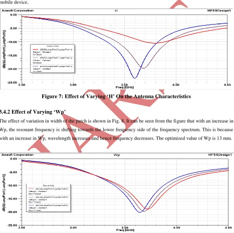
3.4.1 Effect of Varying ‘H’
The effect of variation in air gap between the antenna patch and ground on the return loss characteristics are given in
Fig 7. It can be seen that with the increase in H, resonant frequency of the antenna is shifting towards the lower
frequency side, and better resonance is obtained. However the impedance bandwidth remains almost constant with
an increase in H. The selected value of H is taken 4 mm to keep in view of the small space available inside the
mobile device
.
Figure 7: Effect of Varying ‘H’ On the Antenna Characteristics
3.4.2 Effect of Varying ‘Wp’
The effect of variation in width of the patch is shown in Fig. 8. It can be seen from the figure that with an increase in
Wp, the resonant frequency is shifting towards the lower frequency side of the frequency spectrum. This is because
with an increase in Wp, wavelength increases and hence frequency decreases. The optimized value of Wp is 13 mm.
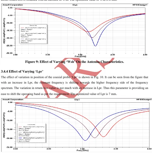
3.4.3 Effect of Varying ‘Wsh’
The effect of variation in width of the shorting strip is shown in Fig. 9. It can be seen from the figure that with an
increase in Wsh, the resonant frequency is shifting towards the higher frequency side of the frequency spectrum.
Better return loss is obtained with an increase in Wsh. The optimized value of Wsh is 2 mm.
Figure 9: Effect of Varying ‘Wsh’ On the Antenna Characteristics.
3.4.4 Effect of Varying ‘Lpr’
The effect of variation in position of the coaxial probe „Lpr‟ is shown in Fig. 10. It can be seen from the figure that
with an increase in Lpr, the resonant frequency is shifting towards the higher frequency side of the frequency
spectrum. The variation in return loss value is not much with an increase in Lpr. Thus this parameter is providing an
ease to shift the operating band as per the requirement. The optimized value of Lpr is 7 mm
.
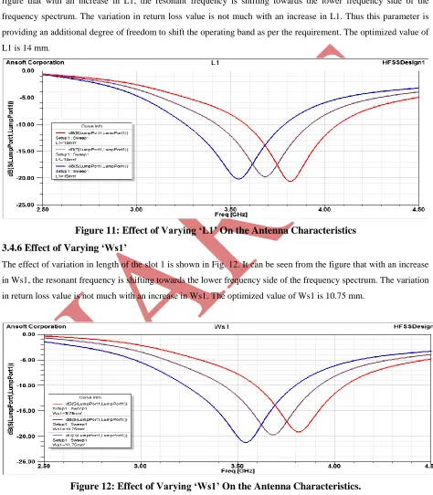
3.4.5 Effect of Varying ‘L1’
The effect of variation in position of the slot loading of the patch „L1‟ is shown in Fig. 11. It can be seen from the
figure that with an increase in L1, the resonant frequency is shifting towards the lower frequency side of the
frequency spectrum. The variation in return loss value is not much with an increase in L1. Thus this parameter is
providing an additional degree of freedom to shift the operating band as per the requirement. The optimized value of
L1 is 14 mm.
Figure 11: Effect of Varying ‘L1’ On the Antenna Characteristics
3.4.6 Effect of Varying ‘Ws1’
The effect of variation in length of the slot 1 is shown in Fig. 12. It can be seen from the figure that with an increase
in Ws1, the resonant frequency is shifting towards the lower frequency side of the frequency spectrum. The variation
in return loss value is not much with an increase in Ws1. The optimized value of Ws1 is 10.75 mm.
Figure 12: Effect of Varying ‘Ws1’ On the Antenna Characteristics.
3.5 Radiation Pattern
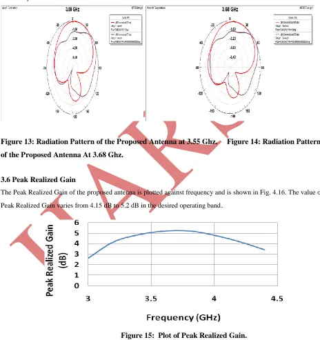
The radiation pattern of the proposed antenna are plotted in XZ-plane (phi = 00) and in YZ-plane (phi = 900) at 3.55
GHz and 3.68 GHz, and are shown in Fig. 13 and Fig 14. Respectively. At 3.55 GHz, main beam is located at theta
= 150 and there is a back lobe. In YZ-plane, beam width is wide and there is null at theta = -1500. Almost similar
radiation pattern is obtained at 3.68 GHz.
Figure 13: Radiation Pattern of the Proposed Antenna at 3.55 Ghz. Figure 14: Radiation Pattern
of the Proposed Antenna At 3.68 Ghz.
3.6 Peak Realized Gain
The Peak Realized Gain of the proposed antenna is plotted against frequency and is shown in Fig. 4.16. The value of
Peak Realized Gain varies from 4.15 dB to 5.2 dB in the desired operating band
.
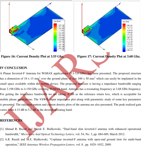
3.7 Current Density Plot
The plot of current density over the antenna patch and ground at 3.55 GHz and 3.68 GHz are shown in Fig. 16 and
17 respectively. It can be seen that maximum current is concentrated near the slot structure present in the patch
.
Figure 16: Current Density Plot at 3.55 Ghz. Figure 17: Current Density Plot at 3.68 Ghz.
IV CONCLUSION
A Planar Inverted-F Antenna for WiMAX applications (3.3-3.8 GHz) has been presented. The proposed structure
has a dimension of 18 x 13 mm2 over the ground plane of size 100 x 50 mm2 which can easily be implanted in the
small space available within the mobile device. The proposed structure is having a impedance bandwidth ranging
from 3.198 GHz to 4.158 GHz covering WiMAX band. Antenna has a resonating frequency at 3.68 GHz frequency.
For getting the impedance bandwidth we are taking -6 dB as the reference return loss, which is acceptable for
mobile phone applications. The VSWR, input impedance plot along with parametric study of some key parameters
is presented. The radiation pattern and current density plots of the antenna are also presented. The peak realized gain
varies from 4.15 dB to 5.2 dB in the desired operating band.
REFERENCES
[1] Ahmad R. Razali and Marek E. Bialkowski, “Dual-band slim inverted-f antenna with enhanced operational
bandwidth,” Microwave And Optical Technology Letters, vol. 54, No. 3, pp. 684-689, March 2012.
[2] A.R. Razali and M.E. Bialkowski, “Coplanar inverted-F antenna with open-end ground slots for multi-band
operation,” IEEE Antennas Wireless Propagation Letters, vol. 8 , pp. 1029–1032, 2009.
[3] Byndas, R. Hossa, M.E. Bialkowski, and P. Kabacik, “Investigations into operation of single and multi-layer
[4] G. Marrocco, “The art of UHF RFID antenna design: Impedance matching and size-reduction technique,” IEEE
Antennas Propagation Magazine, vol. 50, pp. 66–79, 2008.
[5] K. L Virga, Y. Rahmat-Samii, “Low-profile enhanced-bandwidth PIFA antennas for wireless communications
packaging,” IEEE Transactions on Microwave Theory and Techniques, vol. 45, pp.1879-1888, October 1997.
[6] C. T. P Song, P. S. Hall, H. Ghafouri-Shiraz, and D. Wake, “Triple band planar inverted F antennas for handheld
devices,” Electronics Letters, vol. 36, pp. 112-114, January 2000.
[7] Kathleen L. Virga, and Yahya Rahmat-Samii, “Low-profile enhanced-bandwidth PIFA antennas for wireless
communications packaging,” IEEE Transactions on Microwave Theory and Techniques, vol. 45, no. 10, pp.
1879- 1888, October 1997.
[8] P. Nepa, G. Manara, A. A. Serra, and G. Nenna, “Multiband PIFA for WLAN mobile terminals,” IEEE Antennas
and Wireless Propagation Letters, vol. 4, pp. 349-350, 2005.
[9] C. Yang, H. Kim and C. Jung, “Compact broad dual-band antenna using inverted-L and loop for DVB-H
applications,” Electronics Letters, vol. 46, no. 21, 14th October 2010.
[10] Chan Hwang See, Raed A. Abd-Alhameed, Dawei Zhou, and Peter S. Excell, “A planar inverted-F-L antenna
(PIFLA) with a rectangular feeding plate for lower-band UWB applications,” IEEE Antennas and Wireless
Propagation Letters, vol. 9, pp. 149- 151, 2010.
[11] Yong-Sun Shin, Ki-Bok Kong, and Seong-Ook Park, “A compact multiband PIFA with the modified ground
plane and shorting plate for wireless communication applications,” Microwave and Optical Technology Letters,
vol. 50, no. 1, pp. 114-117, 2007.
[12] A.Salamat, M. F. Abdul Kadir, M. R. Che Rose, M. S. R. Mohd Shah, and D. Misman, "The Effect of
Conductor Line to Meander Line Antenna Design," in ASIA-Pacific Conference on Applied Electromagnetic
Proceedings, 2007.
[13] R. Bancroft, "Fundamental Dimension Limits of Antennas," Westminster, Colorado, White paper, Centurion
Wireless Technologies.
[14] M. S. Sharawi, Y. S. Faouri, and S.S. Iqbal, “Design of an Electrically Small Meander Antenna for LTE
Mobile Terminals in The 800 MHz Band”, IEE GCC Conference and Exhibition (GCC), February 19-22,
Dubai, United Arab Emirates, 2011.
[15] T.-Y. Wu, S.-T. Fang, and K.-L. Wong, “Printed diversity monopole antenna for WLAN operation,” Electron.
Lett, vol. 38, no. 25, pp. 1625–1626, Dec. 2002.