18th International Conference on Structural Mechanics in Reactor Technology (SMiRT 18) Beijing, China, August 7-12, 2005 SMiRT18-F07-2
DEVELOPMENT OF COMPUTATIONAL METHODS OF DESIGN BY
ANALYSIS FOR PRESSURE VESSEL COMPONENTS
Shiyi BAO
Institute of Nuclear and New Energy
Technology, Tsinghua University
Phone: +86-10-6278-4809, Fax:
+86-10-6277-1150
E-mail:
[email protected]
Yu ZHOU
Institute of Nuclear and New Energy
Technology, Tsinghua University
Phone: +86-10-6277-2367, Fax:
+86-10-6277-1150
E-mail:
[email protected]Shuyan HE
Institute of Nuclear and New Energy
Technology, Tsinghua University
Phone: +86-10-6278-4825, Fax:
+86-10-6277-1150
E-mail:
[email protected]
Honglin WU
Institute of Nuclear and New Energy
Technology, Tsinghua University
Phone: +86-10-6278-4823, Fax:
+86-10-6277-1150
E-mail:
[email protected]
ABSTRACT
Stress classification is not only one of key steps when pressure vessel component is designed by analysis, but also a difficulty which puzzles engineers and designers at all times. At present, for calculating and categorizing the stress field of pressure vessel components, there are several computation methods of design by analysis such as Stress Equivalent Linearization, Two-Step Approach, Primary Structure method, Elastic Compensation method, GLOSS R-Node method and so on, that are developed and applied. Moreover, ASME code also gives an inelastic method of design by analysis for limiting gross plastic deformation only. When pressure vessel components design by analysis, sometimes there are huge differences between the calculating results for using different calculating and analysis methods mentioned above. As consequence, this is the main reason that affects wide application of design by analysis approach. Recently, a new approach, presented in the new proposal of a European Standard, CEN's unfired pressure vessel standard EN 13445-3, tries to avoid problems of stress classification by analyzing pressure vessel structure’s various failure mechanisms directly based on elastic-plastic theory.
In this paper, some stress classification methods mentioned above, are described briefly. And the computational methods cited in the European pressure vessel standard, such as Deviatoric Map, and nonlinear analysis methods (plastic analysis and limit analysis), are depicted compendiously. Furthermore, the characteristics of computational methods of design by analysis are summarized for selecting the proper computational method when design pressure vessel component by analysis.
Keywords: Stress Classification; Design by Analysis; Pressure Vessel Components
1. INTRODUCTION
DBA is accepted and adopted in the major codes and standards of pressure equipment in the world. Design by Analysis procedure is a design approach based on elastic stress analysis and plastic failure criterion, which requires classifying the calculated stress into primary, secondary and peak categories by performing a detailed stress analysis of the pressure vessel, then applies specified allowable stress limits for different stress categories. It is difficult and impossible for analyzing complex structures until finite element method (FEM) proposed. DBA-approach is flexible and simplifies the incorporation of constructional requirements (wind, snow, earthquake, etc.), if required, in a consistent manner. However, there exist the practical problems associated with the implementation of these design by analysis rules. Those problems are mainly brought by the ASME stress classification (or categorization) method which is used in principle in almost all countries. Hence, stress classification is the considerable criticism in design by analysis procedure.
For calculating stresses of pressure components detailed and classifying the stresses according to ASME codes, there have been developed divers computational methods of stress analysis, such as Stress Equivalent Linearization, Two-Step Approach, Primary Structure method, Elastic Compensation method, GLOSS R-Node method and so on. An inelastic route of DBA is also offer by ASME Boiler & Pressure Vessel Codes Section VIII Division 2. The DBA route in the CEN's unfired pressure vessel standard EN 13445-3 tries to avoid the annoying problem of stress classification by applying limit analysis. In this paper, common computational methods of design by analysis in pressure vessel, especially the Direct Route for Design by Analysis proposed in the CEN's unfired pressure vessel standard EN 13445-3 are introduced, and characteristics of those methods are compared in detail.
2. COMPUTATIONAL METHODS OF DESIGN BY ANALYSIS
According to different analysis approaches, design by analysis can be divided into tow categories: one is design by elastic analysis procedure namely stress categorization, another is design by inelastic analysis procedure based on plastic analysis and limit analysis. The main pressure vessel failure modes, against which the design by elastic analysis procedure is intended to guard by performing a detailed stress analysis of the vessel, are excessive elastic deformation including elastic instability, excessive plastic deformation, plastic instability - incremental collapse (ratcheting) and fatigue.
2.1 Elastic approaches
There are several common methods of stress categorization based elastic analysis, such as Stress Linearization method, Elastic Compensation method, GLOSS R-Node method, Two-Step Approach, Primary Structure method, and so on.
2.1.1 Stress Linearization
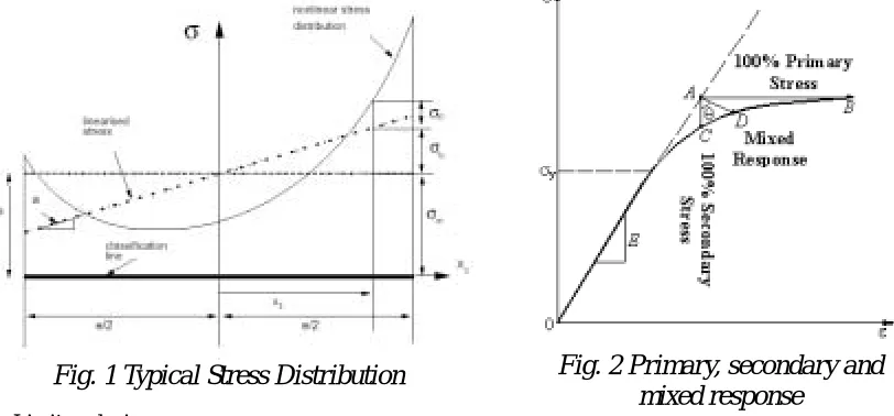
Stress linearization method adopted by ASME Codes originally was first suggested by Kroenke (Kroenke, 1974, 1975) and has been adopted in several finite element postprocessors for classifying the stresses of two-dimension axisymmetric structures. Hollinger and Hechmer believed that this method also could be used to solving the stress classification problem of general three-dimension structures (Hollinger, 1986, 1996). In this method, some stress classification lines (or planes) are chosen in the several dangerous positions on the dangerous cross-section and the stresses are linearised along those lines. The classification line is the smallest segment joining the two sides of the wall where the stress is to be linearised, which means that the stress classification line should perpendicular to inner, outer surfaces, and the mid-surface. According to Kroenke’s procedure, at first, stress distribution results of FEA should transfer from global coordinate system to classification line (or plane) co-ordinate system. Then, the stresses along the stress classification line classify into membrane stress, bending stress and residual nonlinear part of stress -- peak stress by applying resultant force and resultant moment equivalence principle (shown in Fig. 1).
2.1.2 Elastic Compensation Method
Elastic Compensation Method (ECM), named Reduced Modulus Method (RMM) as well, was initially developed as a stress categorization tools for piping systems (Boyle, 1987a, 1987b, Roche, 1986, Dhalla, 1984, Severud, 1984), but was later extended to more general pressure vessel application (Boyle, 1989, 1997, Dhalla, 1987, Mackenzie, 1993, 2000, Marriott, 1988, Nadarajah, 1993, Shi, 1993).
1) Stress classification
The location of the highest stress is defined as the stress categorization point, with effective stress and strain values given by point A in Fig. 2 (where σA>σY, the yield stress of the material). It is argued that if the stress at
hence line AB is defined as the 100% primary stress line. If the stress at point A is secondary, inelasticity will allow the stress to redistribute, but the local strain must be maintained to satisfy compatibility requirements; thus the stress and strain would be given by point C and hence line AC is defined as the 100% secondary stress line. However, if the stress at point A comprises both primary and secondary constituents, a mixed response can be defined by performing an inelastic analysis to calculate the actual inelastic stress and strain at point D, but in the reduced modulus method a simple iterative elastic analysis procedure is used to calculate the approximate slope of the mixed response line by equations (1) and (2).
0
Y D
e E E σ
σ
= (1)
whereED-- the reduced modulus value at point D, GPa; E0-- the original modulus of material, GPa; σY-- the
yield stress, MPa; σe -- the centroidal equivalent stress of the element in the elastic analysis, MPa.
0
1 ( )
tan D A
A D
E ε ε θ
σ σ
− −
=
−
(2)
Where θ -- slope of the mixed response; σA -- usually the equivalent stress of point A by elastic analysis,
MPa; σD -- stress of point D by inelastic analysis, MPa; εA and εD -- strain of point A and D separately,
nondimensional.
Qualitatively, if θ is close to 90o the stress is ‘mostly’ primary, if is θ close to the stress ‘mostly’ secondary and between these limits the stress is mixed.
o 0
Fig. 2 Primary, secondary and
mixed response
2) Limit analysis
Fig. 1 Typical Stress Distribution
If the calculated maximum stress is satisfied the yield stress in the ECM procedure, then the stress field is also satisfied the lower bound limit load theorem and the applied load is namely the lower bound limit load. Then, primary stress totally satisfies the lower bound limit load theorem according to Tresca’s yield condition. For simulating the failure mechanism, in the ECM procedure a series of suitable stress fields are obtained by performing a series of elastic analyses in which the elastic modulus of each element is systematically modified. This causes the stress to redistribute between analyses, giving a series of different statically admissible stress fields. Initially, a conventional elastic analysis is preformed for an arbitrary pressure . This forms iteration zero in a series of linear elastic analyses in which the moduli of elements are changed by equation (3) in order to redistribute the stress in the component (Design by Analysis manual, 2000).
d P
( ) ( )
1 1
n
i i
i
E E σ
σ
− −
= ⋅ (3)
Where, subscript -- the iteration number; i σ( )i−1 -- the maximum unaveraged nodal equivalent stress in
element from the previous solution, MPa; σn -- a nominal value of stress, MPa.
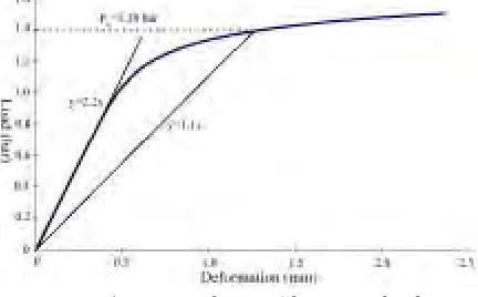
the maximum stress to increase or decrease. Over a number of iterations there will be a net decrease in maximum stress with respect to the initial elastic solution (shown in Fig. 3). The iteration giving σmin, which may or may not be smaller than nominal yield stress of the material σY, is a linear elastic solution and proportional to the applied
load. Therefore, approximate limit load can be given by substituting σmin into equations of limit theorem. As the solution is linear, the maximum stress for solution , i σsimax, is proportional to the applied load ;
thus the maximum load meeting the lower bound theorem maximum stress limit for solution , , is obtained
from equation (4):
d P
i Pli
max
Y li d
si
P P σ
σ
= ⋅ (4)
Where, σsi -- the maximum stress for solution (after stress redistribution), Mpa. i
The best estimate of lower bound limit load given by the ECM is the highest given in the series of solutions:
( )
max
L li
P = P (5)
2.1.3 GLOSS R-Node Method
GLOSS (Generalized Local Stress Strain) R-Node method (Seshadri, 1991a, 1991b, 1996a, 1996b), which is proposed by Seshadri and Fernando, is introduced to for stress classification in pressure vessel components and approximately calculating limit loads of mechanical components and structures. In this method the concept of R-node stresses are used in the determination of the plastic collapse loads of mechanical components. Seshadri claims that when inelastic action occurs, the statically indeterminate stress undergoes redistribution throughout the component except at the R-nodes, which are essentially locations that are statically determinate. Hence the R-nodes are locations where the stress is categorized as primary and so for fixed loads the stresses do not change at these locations throughout the inelastic redistribution process.
The basic GLOSS Rnode procedure is then as follows: A linear analysis is performed to establish the pseudo elastic stress distribution for the prescribed loadings. The elastic modulus of the model is then locally modified on an element by element basis according to equation (6).
0
j m
E E σ
σ
= ⋅ (6)
Where, Em-- the modified element modulus, E0-- is the original modulus, σ -- is the calculated stress
of element, MPa; σj-- a stress value selected so as to result in stress redistribution in most of the
component, MPa.
Then a secondary linear analysis is then performed and the stress distribution compared with the original in order to establish the position of the R-node or nodes, at which the stress will be unchanged. The stress at the R-node corresponding to a given load P is named as the reference stress σref. The limit load for a statically
determinate structure is given by the equation (7). When more than one R-node is obtained an R-node averaging method is used to find an approximation for the limit load.
Y L
ref
P σ P
σ
= (7)
Where, σY-- the yield stress, MPa; P -- given loading of structure, MPa.
2.1.4 Two-Step Approach of Stress Classification
Two-step approach (Lu, 1998, 2000) of stress classification consists of the following steps:
Step 1: According to their function and characteristic, stresses are classified into primary stress and self-limiting stress. Primary stress ( ) is a kind of stress which is necessary to satisfy the equilibrium conditions with the external imposed loading. The basic characteristic of primary stress, which is called load-controlled stress or equilibrium-controlled stress, is that it is not self-limiting. Self-limiting stress, including secondary stress and peak stress (Q ), is a kind of stress which is necessary to satisfy the continuity conditions in the structure or with the external constraint. The main function of self-limiting stress, which is called deformation-controlled stress or continuity-controlled stress, is to satisfy the structural discontinuity.
P
Step 2: According to their distribution and effect range, primary stress is classified into general primary
membrane stress (Pm), local primary membrane stress (PL), and primary bending stress ( ); similarly,
self-limiting stress is classified into secondary stress (Q) and peak stress (
b P F).
2.1.5 Primary Structure Method
Primary structure method (Lu, 1998, 2000) defines two structures as following: 1) Original structure
Original structure is the actual structure. The constraints of original structure are classified into essential constraint and redundant constraint according to their function. Essential constraint is a constraint, which results in necessary reactions to equilibrate the external imposed loading. If it is removed, the structure becomes a movable mechanism and unable to bear the loading. So, stresses caused by the reactions of essential constraint are primary stresses. Redundant constraint is all the constraints except for essential constraints. Stresses caused by redundant constraints are not necessary to equilibrate the external imposed loading, so they may be regarded as secondary stress. But some of them are of benefit for bearing external loading; for this reason redundant constraints can be further classified into favorable redundant constraint and unfavorable redundant constraint.
2) Primary Structures
Primary structure is a reduced structure, which is obtained by removing the unfavorable redundant constraints from considered original structure and is able to bear the external imposed loading. If no unfavorable constraint is removed, the original structure is just a primary structure. In primary structure, all membrane stresses and linearized bending stresses obtained by the equivalent linearization method are primary stresses and no stress is classified as secondary stress. The nonlinearly distributed stresses are peak stresses. Generally speaking, deformation of primary structure does not satisfy the continuity conditions.
In primary structure method procedure, at first, take the original structure as a primary structure, and compute its total stress field by finite element method. Once find the primary structure, and then compute primary stress field of the structure by finite element method. Subtraction of primary stress in the primary structure from total stress in the original structure is a self-limiting stress field. At last, stress is decomposed by the equivalent linearization method (ELM).
2.2 Inelastic approaches
The ASME VIII Division 2 rules for inelastic analysis are given in Appendix 4-136 Applications of Plastic Analysis. These rules provide guidance in the application of plastic analysis and some relaxation of the basic stress limits which are allowed if plastic analysis is used. The rules for inelastic analysis considered here pertain to calculation of permissible loads for gross plastic deformation only. Two types of analysis may be used to calculate allowable loads for gross plastic deformation: limit analysis and plastic analysis. Rules are given in the Code for shakedown analysis but in practice shakedown analysis is difficult and it is simpler to apply the limit to an elastic analysis.
3Sm
The plastic limit load is determined by Twice-elastic-slope (TES) method for experimental stress analysis or nonlinear stress analysis in ASME VIII and III. A limit load of plastic analysis is defined to be the value at the intercept of a line drawn from the origin of a pressure-deformation curve at a slope of twice the slope of the elastic portion of the curve (see Fig. 4).
3. COMPUTATIONAL METHODS IN THE EUROPEAN STANDARD 3.1 European Pressure Vessel Standard
As pointing out by the Design-by-Analysis Manual published by the European Pressure Equipment Research Council (EPERC), All these DBA routes in the major codes and standards in the pressure equipment field which are based on the rules first proposed in the ASME Pressure Vessel and Boiler Code lead to the same well-known problems, especially the stress categorization problem, and all are outof-step with the continuing development of computer hardware and software. For avoiding those problems, the new European pressure vessel standard EN 13445-3: Part 3 Unfired Pressure Vessels is published in 2002 by the European Committee for Standardization (CEN) Technical Committee TC54. The European Standard has introduced the possibility of satisfying the requirement to avoid various failure mechanisms directly through the detailed rules embodied in the new Direct Route which is similar to the one used in Eurocodes (for steel structures), using the notions of principles and application rules as well as the notion of partial safety factors, while retaining the ‘conventional’ elastic route which uses stress categorization for designing simple thin-walled structures by analysis. In addition it also introduces several new concepts to help overcome the known difficulties with the current design by analysis approach and to assist the formulation of the Direct Route.
For analyzing the structure directly, several analysis and calculation methods such as Elastic Compensation Method, Deviatoric Map, and traditional nonlinear analysis methods are list in the European Standard. The following failure modes which designate the design checks are incorporated in the first issue of the standard: Gross plastic deformation (GPD) with corresponding failure modes being ductile rupture and excessive local strains, Progressive plastic deformation (PD), Instability (I), Fatigue (F) and Static equilibrium (SE), where former three failure modes are qualified by limit theorem, shakedown theorem and fatigue theorem separately.
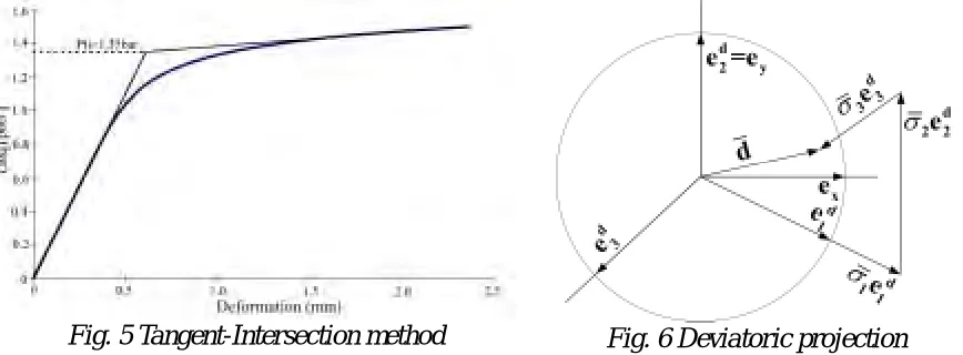
For obtaining the convergent solution for calculating plastic load, the Standard suggests that a linear strengthening elastic-plastic material model substituting an elastic-perfectly plastic (or rigid-perfectly plastic) material model. The tangent-intersection method is used in the European Standard for determining lower-bound limit load according to load-deformation curve (see Fig. 5).
3.2 Deviatoric Map
The deviatoric projection (Preiss, 1997, Zeman, 1999) is a simple tool in plasticity theory for visualizing stresses states vis-a-vis to yield conditions. In principle, it is the projection of the stress point in the (three-dimensional, Cartesian) space of principal stresses—with coordinates in the directions of the unit vectors
, , equal to the three principal stresses—onto the deviatoric plane, also often called p-plane, i.e. the
plane which is normal to the hydrostatic axis given by equal principal stresses. The coordinates of this projection
point in the coordinate system , ,
equal the principal values of the stress deviator.
1
e e2 e3
1
e e2 e3
Using this deviatoric projection as a tool, this projection point can be obtained quite simply by vector addition of with arbitrary scale, see Fig. 6; quite conveniently σi =σi/RM, i=1, 2,3; can be used instead of σi, where
is the appropriate relevant strength parameter.
RM
If the considered vector corresponds to the stress in a specific point of the structure due to a specific action, the location of its end point vis-a-vis a limit curve, e.g. the unit circle with center in the origin which corresponds to Mises’ yield condition, clearly visualizes the instantaneous behavior of the structure under the considered action: If the end point is not outside of the limit curve, the stress state is compatible with the corresponding yield
d
condition; if it is on the limit curve, plastic deformation may occur ‘‘at the structural point’’. If the action changes—and the orientation of the principal axes does not change—the stress state may change, and the vector
may change.
d
If a cyclic action results in a cyclic stress state, the vector will describe a closed curve in this deviatoric map. A curve completely inside of the limit curve corresponds only to elastic stress states, portions on the limit curve correspond to plastic flow, portions outside are possible only in case of hardening, or for fictitious stress states, e.g. for a fictitious unlimited linear elastic constitutive law.
The extension of this procedure to more than two actions, or to more than one self equilibrating stress, including, of course, those due to thermal stresses, is obvious and straightforward.
4. COMPARION OF COMPUTATIONAL METHODS
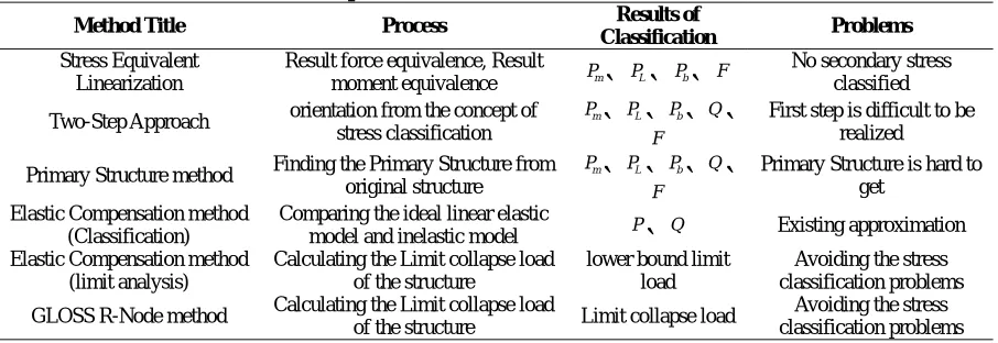
The characteristics of the computational methods of design by analysis are compared with pressure vessel acted as computational example in the Table 1. In the Table 1, it is difficult for classifying the stresses by using the first four methods in the practical design by analysis. Because current codes and standards of design by analysis do not offer the guiding code’s criteria about how to ensure the correctness of finite element analysis especially how to classify the stresses for numerical solutions. Elastic Compensation method (for limit analysis) and GLOSS R-Node method are a means of avoiding stress classification problem by calculating limit collapse load of the structure.
Table 1 Comparison of Stress Classification Methods
Method Title Process Results of
Classification Problems
Stress Equivalent Linearization
Result force equivalence, Result
moment equivalence Pm PL Pb F
No secondary stress classified
Two-Step Approach orientation from the concept of stress classification
m
P PL Pb Q
F
First step is difficult to be realized
Primary Structure method Finding the Primary Structure from original structure
m
P PL Pb Q
F
Primary Structure is hard to get
Elastic Compensation method (Classification)
Comparing the ideal linear elastic
model and inelastic model P Q Existing approximation
Elastic Compensation method (limit analysis)
Calculating the Limit collapse load of the structure
lower bound limit load
Avoiding the stress classification problems
GLOSS R-Node method Calculating the Limit collapse load
of the structure Limit collapse load
Avoiding the stress classification problems
Elastic Compensation method is one of a number of design methods cited in the new CEN European pressure vessel design by analysis manual and has been the preferred method of the Japan Society of Mechanical Engineers (JSME) committee reviewing code requirements. The elastic compensation method is recommended for pressure vessel design in the ASME Task group report (Pastor, 1997) on primary stress as a means of avoiding the stress categorization problem.
While check against Progressive Plastic Deformation (PD) by the deviatoric map in the Europe Standard EN 13445-3, it is convenient to visualize two situations: constant principal stress axes and changing principal stress axes. Since it is stated in the standard that the requirement given in this application is only a necessary and not a sufficient condition for check against PD. If the structure satisfies the requirements for check against GPD at the same loading, the requirement is also a sufficient condition. The check against PD can be performed for a stress-concentration-free structure for avoiding the stress singularities problem, which should be studied in the future.
5. CONCLUSIONS
analysis methods directly and taking advantage of recent improvements in finite element software and computer power. Furthermore, EN 13445 is selected as EPR Codes and Standards for class 3 equipments (Faidy, 2005). As results, inelastic analysis methods based on elastic-plastic theorem become the development trend of design by analysis.
REFERENCES
[1] Kroenke W C., Classification of Finite Element Stresses According to ASME Section III Stresses Categories [J]. Pressure Vessels and Piping, Analysis and Computers, ASME, 1974, 34: 78-83.
[2] Kroenke W C, Addicott. G W, Hinton B M., Interpretation of Finite Element Stresses According to ASME Section III [J]. ASME Pressure Vessel and Piping, 1975, 63: 98-112.
[3] Hollinger G L, Hechmer J L., Three-Dimensional Stress Criteria-A Weak Link in Vessel Design and Analysis [J], ASME Pressure Vessel and Piping, 1986, 109: 914.
[4] Hollinger G L, Hechmer J L., Summary of Example Problems from PVRC Project on Three Dimensional Stress Criteria [J]. ASME Pressure Vessel and Piping, 1996, 338: 1924.
[5] Design by Analysis manual - Work developed through the European Pressure Equipment Research Council (EPERC) – June 2000.
[6] Boyle, J. T., Speace, J., A procedure for the assessment of elastic follows up in high temperature piping systems [J]. Design and analysis of piping, pressure vessels and components (Eds W. E. Short et al.), 1987a, 120: 197-201.
[7] Boyle, J. T., Nakamura, K., The assessment of elastic follow-up in high temperature piping systems [J]. Int. J. Pressure Vessel and Piping, 1987b, 29: 167-194.
[8] Roche, R. L., Estimation of piping elastic follow-up by using conventional computation [J]. Int. J. Pressure Vessel and Piping, 1986, 26: 53-78.
[9] Dhalla, A. K., Verification of an elastic procedure to estimate follow-up [J]. Design of elevated temperature piping (Eds R. H. Mallet and R. M. Mello), PVP, 1984, 86: 81-96 (The American Society of Mechanical Engineers, New York).
[10] Severud, L. K., A simplified method vessel technology San Francisco[C]. 1984: pp. 367-387 (The American Society of Mechanical Evaluation for piping elastic follow-up, Proceedings of Fifth International conference on pressure engineers, New York).,
[11] Boyle, J. T., Elastic following up and the categorization of secondary stress [J]. ASME Pressure Vessel and Piping, 1989, 161, pp47-53.
[12] Boyle J.T., Hamilton R., Shi J., Mackenzie D., A simple method of calculating lower-bound limit loads for axisymmetric thin shells, Journal of pressure vessel technology, 1997, 119: 236-242.
[13] Dhalla, A. K., A simplified procedure to classify stresses for elevated temperature severance [J]. Design and analysis of piping, pressure vessels and components (Eds W. E. Short et al.), PVP, 1987, 120: 177-188. [14] Mackenzie, D. and Boyle, J.T., A method of estimating limit loads by iterative elastic analysis I - Simple
examples, Int. J. Pres. Ves. and Piping, 1993, 53, pp77-95.
[15] Mackenzie D., Boyle J.T., Hamilton R., Elastic compensation method for limit and shakedown analyses: A review, Jrnl. of Strain Analysis for Eng. Design, 2000, 35 (3): 171-188.
[16] Marriott, D. L., Evaluation of deformation or load control of stresses under inelastic conditions using elastic finite element stress analysis[C]. Proceeding of ASME Conference on Pressure Vessel and Piping, Pittsburgh, 1988, 136:147-154.
[17] Nadarajah, C., Mackenzie, D., Boyle, J.T., A method of estimating limit loads by iterative elastic analysis II - Nozzle/sphere intersection under internal pressure and radial loading, Int. J. of Pres. Ves. and piping. 1993, 53: 97-120.
[18] Shi, J., Mackenzie, D. and Boyle, J.T., A method of estimating limit loads by iterative elastic analysis III - Torispherical heads under internal pressure, Int. J. of Pres. Ves. and piping. 1993, 53: 121-142.
[19] Seshadri, R., Fernando, C. P. D., Limit loads of mechanical components and structures using the GLOSS r-node method [J]. ASME Pressure Vessel and Piping, 1991a, 210: 125-134.
[20] Seshadri, R., The generalized local stress strain (GLOSS) analysis theory and application[J]. ASME J.
Pressure Vessel Technology, 1991b, 25: 219-227.
[22] Seshadri, R., Robust Stress-Classifcation of Pressure Components Using the GLOSS and GLOSS R-Node Methods, Journal of Pressure Vessel Technology, 1996b, 118: 208-215.
[23] Lu Mingwan, Chen Yong, Li jianguo. Primary Structure Method of Stress Classification for Design by Analysis [J]. Nuclear Power Engineering, 1998, 19(4): 330-337.
[24] Lu Ming-Wan, Chen Yong, Li Jian-Guo, Two-Step Approach of Stress Classification and Primary Structure Method, Journal of Pressure Vessel Technology, 2000, Vol. 122, pp2-8.
[25] Preiss, R., On the shakedown analysis of nozzles using elasto-plastic FEA. International Journal of Pressure Vessel and Piping, 1999, Vol. 76, pp. 421-434.
[26] Zeman, J.L. Preiss, R, The deviatoric map – a simple tool in design by analysis. International Journal of Pressure Vessel and Piping, 1999, Vol. 76, pp. 339-344.
[27] Pastor, T.P., Hechmer, J., ASME Task group report on primary stress, J. of Pres. Ves. Technology, 1997, 119: 61-67.