Contents lists available atScienceDirect
Fusion Engineering and Design
j o u r n a l h o m e p a g e :w w w . e l s e v i e r . c o m / l o c a t e / f u s e n g d e sThe TBM-CA configuration management approach for the ITER test blanket
module - application to the HCLL TBS
L. Jourd’Heuil
a,∗, D. Panayotov
b, J.-F. Salavy
c, C. Storto
d, M. Colombo
d, P. Sardain
aaCEA, IRFM, F-13108 Saint-Paul-lez-Durance, France
bKIT, Hermann-von-Helmholtz-Platz 1, D-76344 Eggenstein-Leopoldshafen cCEA, DEN, Saclay, DM2S, F-91191 Gif-sur-Yvette, France
dLGM, Espace Wagner, Bâtiment D, 10 rue du Lieutenant Paraye, F-13858 Aix-en-Provence Cedex 3
a r t i c l e i n f o
Article history:Available online 8 May 2011
Keywords: TBM TBS Configuration Management Change Management Nonconformance Management Organization
a b s t r a c t
The European Test Blanket Modules (EU-TBM) are first prototypes of a fusion reactor breeding blanket. They will be tested in dedicated equatorial ports n◦16 of ITER. Technical developments are performed by a Consortium of European Associates (TBM-CA) and supported within the framework of F4E agency. Designing a complex nuclear system like TBM for ITER necessitates an organizational structure inside the consortium to manage in permanence the coherence between requirements (F4E technical and manage-ment specifications) and the TBM developmanage-ment through their life time. At the present stage, evolutionary nature of the design from the different teams is important. Highest priority is assigned to the Manage-ment support and Design Integration Team (MDIT) to perform an efficient control of the Configuration Management (CM). The TBM-CA CM comprises 4 main processes: a) identifying configuration of a product characteristics, including its interfaces (Configuration identification), b) controlling the evolution from agreed baseline (Configuration Control), c) creating the knowledge database in order to manage the infor-mation all along the lifecycle of the items (Configuration status accounting) and d) verifying the current configuration status of the items (Audits).
CM is then a powerful tool to link the requirements for engineering, safety, quality assurance and test & acceptance activities. The application of the CM approach is illustrated through the case of TBM-HCLL (Helium Cooled Lithium Lead). The result shows that the proposed methodology and tools are suitable and provide quality solution for the items with a complex configuration such as TBM HCLL.
© 2011 Elsevier B.V. All rights reserved.
1. Introduction
The European Test Blanket Modules (EU-TBM) are first proto-types of a fusion reactor breeding blanket. They will be tested in
dedicated equatorial ports n◦16 of ITER. Technical developments
are performed by a Consortium of European Associations (TBM-CA) and supported within the framework of F4E agency. For unique, complex and costly component such as Test Blanket Systems (TBS) for ITER, the European consortium TBM-CA developed an organi-zation to define, monitor and control the compliance of the system according to the requirements and technical specifications all along the life cycle of the TBM sets. The MDIT is the group responsible for the Configuration Management tasks since 2009 in the framework of the grants awarded by F4E. The MDIT combines several units involved in these configuration tasks: a) the Configuration Officer who is responsible to control the configuration process, including the interface management, b) the Quality Officer in charge of the
∗Corresponding author.
E-mail address:[email protected](L. Jourd’Heuil).
change and nonconformance processes which can directly affect the design, c) and the Central Design Office that provides CAD models.
A Configuration Control Board (CCB) was created also to determine the configuration baseline. This baseline includes the approved requirements (functional and physical) per Configuration
Items, interfaces, quality/safety requirements. . .The CCB is chaired
by the Configuration Officer.
Due to the evolutionary nature of the present design of the TBS, it became very important for the Consortium to control the config-uration items, because the products are shared among the different teams in 6 European Institutes. One can change a part, with a deep impact in another sub-system.
To be able to freeze the Configuration items as “baseline” is a prime importance for the functional behavior of the con-sortium. Then the Baseline can be shared by all the teams and the CCB can control the validated change and the distribution of information. In addition, the baseline established by the CCB includes the project control (schedule, risk, resource and cost) and documentation (Smarteam and Document Management System based on SharePoint 2007).
0920-3796/$ – see front matter © 2011 Elsevier B.V. All rights reserved. doi:10.1016/j.fusengdes.2011.03.101
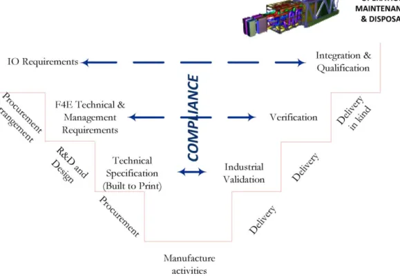
Fig. 1.CM in the life cycle of the TBS.
This paper aims to describe the TBM-CA configuration manage-ment through an example with one of the two TBS European types: the Helium Cooled Lithium Lead (HCLL) concept developed by CEA[1].
2. Principles of configuration and main characteristic of TBM-CA approach
The TBM-CA Configuration procedure is drawn according to
the ISO 10007:2003 standard[2]. The Configuration Management
(CM) is used for the establishment and the control of the product’s functional and physical characteristics compared to its design and operational requirements. The CM will be applied throughout the entire life cycle of the product in the framework of the contract awarded by F4E or IO.
The CM allows the TBM-CA Team members to:
•access to the technical description of a Configuration Item using
approved documentation by F4E and IO,
•control the internal interfaces and monitor the external ones;
•record the approved modifications of the technical description of
a Configuration item;
•get an up-dated product definition from the baseline, in real time
frame (Configuration Status Accounting),
•verify that technical description remains the exact products to be
delivered to IO according to its requirements;
This approach is similar to the one presented in[3–5]for ITER
or in[6,7]for other facilities.
3. Method
3.1. Configuration management plan
When the management requirements are applicable (Quality Plan approved), all the TBM-CA team members can use the
configu-ration process defined by the consortium. The Quality Plan includes a Configuration Management Plan. This configuration Management Plan must be executed also by all the Consortium’s suppliers.
Interfaces Management is an integral part of Configuration Man-agement. It is detailed in[8](Fig. 1).
3.2. Implementation of configuration management
Implementation of configuration management comprises the following processes:
•the management of the requirements (Microsoft Excel files),
•the Configuration Identification that includes the selection of
Configuration items and the record of the Documentation Con-figuration Baseline (Sharepoint),
•the Configuration Verification where the Configuration Control
Board approve the baseline by reviews,
•the Configuration Control (change management and
noncon-formance processes; approval of the deliverables recorded in sharepoint)
•the Configuration Status Accounting (Configuration items
defini-tion and approved modificadefini-tion–change, nonconformance–new deliverables recorded in a Microsoft Excel files)
•the Configuration Audits (demonstration that each CI
(Configu-ration Item) meets its documented functional, performance and physical characteristics and verify the efficiency of the TBM-CA Configuration Management)
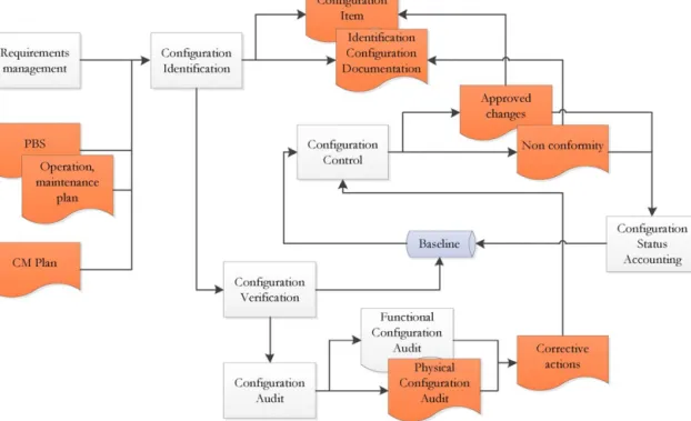
The implementation is described inFig. 2.
4. Results
4.1. HCLL EM-TBM configuration item
For the Electromagnetic TBM (HCLL EM-TBM), the product tree
Fig. 2.CM implementation in TBM-CA.
From this input data, the consortium added several levels to achieve the work to be done in the framework of the contract. It’s still a high level PBS, but it allows us to define the Configuration items.
There are four identified Configuration Items for the HCLL EM-TBM (Fig. 3):
•Breeder Zone (56.A1.M1.S1.X1)
•Generic Box (56.A1.M1.S1.X2)
Fig. 3.Configuration items of the HCLL EM TBM.
•Stiffening Grid (56.A1.M1.S1.X3)
•Manifold (56.A1.M1.S1.X4)
•Instrumentation (56.A1.M1.S1.X5)
4.2. Documentation configuration baseline
For each CI, the existing related documentation is identified and
recorded (Fig. 4). For all CI, 54 documents constituted the baseline
to start the tasks.
4.3. Configuration baseline
Configuration baselines represent the approved version of requirements and design. The configuration baseline is established during technical reviews. In the framework of a contract awarded by F4E, there must be two important milestones:
a) After the KoM, when input data are submitted by F4E, the first baseline can be established by the CCB and can be qualified “as required”.
b) Before the final meeting, when all the deliverables with their acceptance data package are accepted by F4E, the second base-line can be established by the CCB and can be qualified “as defined” for the actual phase of the TBM project.
The configuration baseline describes the physical and functional characteristics of the configuration items issued from the Docu-mentation Configuration Baseline and CAD data file.
One of the feedbacks from actual contracts is that the establish-ment of this baseline needs about a month to prepare the review, and has to be incorporated in the schedule from now on. The tech-nical tasks cannot start prior the review process.
4.4. Configuration status accounting (CSA)
TBM-CA developed a data file to establish the Configuration Status Accounting to record, store and retrieve the following con-figuration data:
Fig. 4.HCLL EM-TBM Documentation Configuration Baseline.
•status of F4E requirements;
•status of the HCLL TBM configuration baseline;
•design status of the configuration items (into Smarteam/Catia);
•status of HCLL TBM deliverables, once approved by F4E;
•status of HCLL TBM configuration documentation baseline and
configuration data sets;
•status of approval of changes and deviations and their status of
implementation;
•status of actions derived from technical reviews and
configura-tion verificaconfigura-tion reviews.
Doing this, TBM-AC assumes to catch the complete design docu-mentation of the HCLL EM-TBM. But the amount of data to manage is quite huge. The use of a simple tool such as Excel data file will limit the efficiency of the method. An improvement way could be to adopt a configuration management tool at the level of MDIT. 4.5. Configuration control
Change control procedures are applied following the establish-ment of the first baseline by the CCB.
Configuration control ensures that all changes or deviations to agreed configuration baselines, including their released and approved documentation are processed and controlled in a trace-able manner.
When a new requirement is notified by F4E, an impact assess-ment on the task must be provided to the CCB by the technical staff. This assessment will help F4E and the CCB to approve the change. Then, the CSA is updated with the related documentation. In the case where the change is proposed by the consortium member team, there are two processes to manage it:
•Major deviation (when a F4E requirement is modified), through
the prior F4E validation;
•Minor deviation (for other configuration baseline items) where
the CCB must adopt the proposition.
Once approved, MDIT is in charge of the process for control-ling the evolution of the baseline. It includes the preparation,
Fig. 5.This figure illustrates how the links are established for each CI between the Documentation Configuration Baseline (red arrow), the F4E requirements and the check of the compliance into the deliverables (blue arrow and green circle). (For interpretation of the references to colour in this figure legend, the reader is referred to the web version of the article.)
justification, evaluation, disposition and implementation of engi-neering and contractual changes and deviations.
From each deliverable approved by F4E, the new characteristics of the HCLL issued from the results are included into the CSA. MDIT
can also easily check the compliance with F4E requirements (Fig. 5).
The feedback of present contracts shows a lack of implementa-tion of this configuraimplementa-tion control process by both F4E and TBM-CA (no change or deviation recorded!). This is not critical in the pre-liminary conceptual design phase. But this issue must be tackled rapidly by a culture change. The advantage shown by the case study on HCLL TBM is a great step towards a better dissemination and acceptance of the method by TBM-CA member team.
5. Conclusion
After months of development during the first contract with F4E, the system that allows an efficient TBM-CA Configuration Control is established with the associated tools. The result shows that the proposed methodology is suitable and provides quality solution for the items with a complex configuration such as HCLL EM-TBS.
CM supply confidence in the system throughout its develop-ment and check that the system and all its parts do what is wanted, allow derivation coverage analysis, and prevent over design or omitted needs
This traceability allows analysis such as impact analysis, impact coverage analysis and derivation analysis before to submit it to F4E. The system shall be applied for future contract with F4E.
Possible improvements are foreseen: benchmark of Configuration Management tools in order to avoid working with MS Excel and a specific training program to help the team members to adopt the method.
Acknowledgement
This work was supported within the framework of the F4E-2008-GRT-009.
References
[1] J.-F. Salavy, et al., The HCLL Test Blanket Module system: Present reference design, system integration in ITER and R&D needs, Fusion Eng. Des. 83 (2008) 1157–1162.
[2] Quality Management Systems - Guidelines for Configuration Management, ISO 10007:2003.
[3] S. Chiocchio, et al., System engineering and configuration management in ITER, Fusion Eng. Des. 82 (2007) 548–554.
[4] A. Muhammad, et al., Combined application of Product Lifecycle and Software Configuration Management systems for ITER remote handling, Fusion Eng. Des. 84 (2009) 1367–1371.
[5] T. Gassmann et al. Integration of IC/EC systems in ITER. doi:10.1016/j.fusengdes.2010.03.013.
[6] R. Brakel, et al., Configuration Management for Wendelstein 7-X, Fusion Eng. and Des. 84 (2009) 505–508.
[7] Claude Pascal, Christian Blanchet, Jean-Marc Ollivier. The value of modern decision-making support services to fusion projects. Fusion Eng. Des. 82 (2007) 2713-2721.
[8] D. Panayotov et al., System engineering approach in the EU Test Blanket Systems Design Integration. This conference.