DAMPER ACTUATORS 20/34 Nm (177/300 lb-in)
FOR FLOATING / 2-POSITION CONTROL
GENERAL
These direct-coupled damper actuators provide two-position and floating control for:
• air dampers,
• VAV units,
• air handlers,
• ventilation flaps,
• louvers, and
• reliable control for air damper applications for up to 4 m2 (air friction-dependent).
FEATURES
• New self-centering shaft adapter
• Access cover to facilitate connectivity
• Declutch for manual adjustment
• Mechanical end limits
• Field-installable auxiliary switches
• Silent drive operation
• Pre-wired
• Rotation direction selectable by switch
• Mountable in any orientation (except upside down)
• Mechanical position indicator
SPECIFICATIONS
Supply voltage N2024/N3424 24 Vac ±15%, 50 Hz N20230/N34230 230 Vac ±15%, 50 Hz Nominal voltage N2024/N3424 24 Vac, 50 Hz N20230/N34230 230 Vac, 50 HzAll values stated hereinafter apply to operation under nominal voltage conditions.
Power consumption
N2024/N20230 6 VA / 3 W
N3424/N34230 7 VA / 7 W
Ambient limits
Ambient operating limits -20...+60 °C (-5...+140 °F) Ambient storage limits -40...+80 °C (-40...+175 °F)
Relative humidity 5...95%, non-condensing
Cables
Length 1 m
Materials silicone-free
Safety
Protection standard IP54 as per EN60529
Protection class II as per EN 60730-1
Lifetime
Full strokes 60000
Repositions 1.5 million
Mounting
Round damper shaft 10...27 mm
Square damper shaft 10...18 mm; 45° steps
Shaft length min. 22 mm
Auxiliary switch (when included)
Rating 5 A (resistive) / 3 A (inductive)
Triggering points 5° / 85° Torque rating N2024/N20230 20 Nm (177 lb-in) N3424/N34230 34 Nm (300 lb-in) Runtime 110 seconds Rotation stroke 95°± 3°
Dimensions see "Dimensions" on page 8
Weight (without cables) 1.45 kg (3 lbs. 3 oz.)
Noise rating 40 dB(A) max. at 1 m
MODELS
Order number Supply voltage Auxiliary switches Feedback Power consumption Torque
N2024/N2024-2POS 24 Vac -- --N2024-SW2 24 Vac 2 --N2024-P10K 24 Vac -- 10 Kohm N20230/N20230-2POS 230 Vac -- --N20230-SW2 230 Vac 2 --N20230-P10K 230 Vac -- 10 Kohm 6 VA / 3 W 20 Nm (177 lb-in) N3424 24 Vac -- --N34230 230 Vac -- -- 7 VA / 7 W 34 Nm (300 lb-in)
Product Identification System
SmartAct N 2 0 2 3 0
N
S = spring return = no spring return
20 34 = 20 Nm = 34 Nm 010 24 230 = modulating = 24-volt floating/on-off
= 230-volt floating/on-off If additional elements are required, please complete as follows:= On/Off = Fire and Smoke
= Variable Air Volume = LonWorks
= Enhanced (serial interface + span + offset) = feedback potentiometer, 500 Ohms = feedback 1000 Ohms = feedback 5000 Ohms = feedback 10 kOhm = two built-in auxiliary switches
potentiometer, potentiometer, potentiometer, -2POS -F -VAV -LON -SER -P500 -P1000 -P5000 -P10K -SW2
= not currently available
X
Fig. 1. Product Identification System
OPERATION / FUNCTIONS
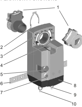
Fig. 2. Setting units and control elements
Legend for Fig. 2:
1 Self-centering shaft adapter 2 Retainer clip
3 Rotational angle scales (0...90° / 90...0°) 4 Mechanical end limits (not applicable for N34xx)
5 Declutch button
6 Anti-rotation bracket 7 Rotation direction switch
8 Access cover
9 Internal auxiliary switch wire 10 Power and control switch wire
Contents of Package
The delivery package includes the actuator, itself, parts 1 through 10 (see Fig. 2), the anti-rotation bracket screws, and the SM mounting plate and screws.
Rotary Movement
The rotation direction (clockwise or counterclockwise) can be selected using the rotation direction switch (see part 7 in Fig. 2), thus eliminating the need to re-wire. To ensure tight closing of the dampers, the actuator has a total rotation stroke of 95°.
As soon as operating power is applied, the actuator may start to run. When power is removed, the actuator remains in position. For actuator-controller wiring instructions, see section "Wiring" on page 4.
Rotation Direction Switch
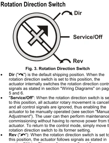
Fig. 3. Rotation Direction Switch
• Dir (" ") is the default shipping position. When the rotation direction switch is set to this position, the actuator internally switches the rotation direction control signals as stated in section "Wiring Diagrams" on pages 5 and 6.
• "Service/Off": When the rotation direction switch is set to this position, all actuator rotary movement is cancelled and all control signals are ignored, thus enabling the actuator to be manually operated (see section "Manual Adjustment"). The user can then perform maintenance / commissioning without having to remove power from the actuator. To return to the control mode, simply move the rotation direction switch to its former setting.
• Rev (" "): When the rotation direction switch is set to this position, the actuator follows signals as stated in section "Wiring Diagrams" on pages 5 and 6.
Two-Position or Floating Control
The actuator is capable of being operated by either a two-position (open/close) or a floating (three-wire) controller. Refer to wiring diagrams for correct connection.
Feedback Signal
Actuators equipped with a feedback potentiometer provide position feedback via the potentiometer resistance value (see Fig. 4). white white white P2 P3 500 Ohm or 1 kOhm or 5 kOhm or 10 kOhm P1 totally CCW = max. ohm totally CW = 0 ohm totally CCW = 0 ohm totally CW = max. ohm
Fig. 4. Feedback signal settings
If, while the actuator is not rotating, the user declutches it and manually repositions the shaft adapter, the feedback signal will then follow the new position at which the shaft adapter has been left.
Position Indication
The hub adapter indicates the rotation angle position by means of the rotational angle scales (0...90° / 90...0°) provided in the actuator plate (see Fig. 5).
Fig. 5. Position indication
Manual Adjustment
IMPORTANT
To prevent equipment damage, you must remove power or set the rotation direction switch to the "Service/Off" position before manual adjustment. After removing power or setting the rotation direction switch to the "Service/Off" position, the gear train can be
disengaged using the declutch button, permitting the actuator shaft to be manually rotated to any position. The feedback signal will then follow the new position.
Limitation of Rotation Stroke
Two adjustable mechanical end limits are provided (not applicable for N34xx) to limit the angle of rotation as desired (see Fig. 6).
Fig. 6. Mechanical end limits
The mechanical end limits must be securely fastened in place as shown in Fig. 7. Specifically, it is important that they properly mesh with the rotational angle scales when the screws are tightened.
Internal Auxiliary Switches
NOTE: Only those actuators for which "-SW2" has been
specified when ordering (e.g.: "N2024-SW2") feature internal auxiliary switches.
The internal auxiliary switches are set to switch from "common" to "normally open" at angles of 5° and 85°, respectively, from the totally counterclockwise position.
Fig. 8. Internal auxiliary switch triggering points
INSTALLATION
These actuators are designed for single-point mounting.
IMPORTANT
In order to prevent equipment damage, you must remove power or set the rotation direction switch to the "Service/Off" position before manual operation.
Mounting Instructions
All information and steps are included in the Installation Instructions supplied with the actuator.
Mounting Position
The actuators can be mounted in any position (except upside down). Choose a mounting position permitting easy access to the actuator's cables and controls.
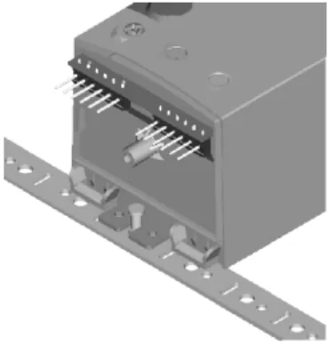
Mounting Bracket and Screws
If the actuator is to be mounted directly on a damper shaft, use the mounting bracket and screws included in the delivery package.
Self-Centering Shaft Adapter
The self-centering shaft adapter can be used for shafts having various diameters (10...27 mm) and shapes (square or round).
In the case of short shafts, the shaft adapter may be reversed and mounted on the duct side.
Stroke Limitation with Mechanical End Limits
The mechanical end limits (not applicable for N34xx) enable the stroke to be limited from 0...90° in increments of 3°.
Wiring
Access Cover
To facilitate wiring the actuator to the controller, the access cover can be detached from the actuator.
IMPORTANT
Remove power before detaching the access cover.
Once the access cover has been removed, please take care to avoid damaging any of the parts now accessible.
Fig. 9. Access cover (N2024-SW2)
Depending upon the model, the access cover may have one or two terminal strips, including a lay-out with a description for each of the terminals.
Wiring Diagrams
N2024 / N2024-2POS / N3424 N2024-SW2 Terminal strip 1Floating control
Two-position control
24 Vac~ 3 2 1 rotation direction switch 24 V M~ rotation direction switch 3 2 1 24 V M~ 24 Vac~ Auxiliary switches Service/Off Service/Off Auxiliary switches S1 S2 S3 S4 S5 S6 S3 black S2 black S1 black S6 gray S5 gray S4 gray brown 2 blue 1 white 3 brown 2 blue 1 white 3 Dir Rev Dir RevConnect via safety isolating transformer!
!
!
Connect via safety isolating transformer!N2024-P10K Terminal strip 1
Floating control
Two-position control
24 Vac~ 3 2 1 rotation direction switch 24 V M~ rotation direction switch 3 2 1 24 V M~ 24 Vac~ Feedback potentiometer white white white P2 P3 500 Ohm or 1 kOhm or 5 kOhm or 10 kOhm P1 Feedback potentiometer Service/Off Service/Off black 2 blue 1 white 3 brown 2 blue 1 white 3 Dir Rev Dir RevConnect via safety isolating transformer!
! ! Connect via safety isolating transformer!
totally CCW = max. ohm totally CW = 0 ohm totally CCW = 0 ohm totally CW = max. ohm Name
Connecting cable Terminal Wire color Wire print
Floating Two-position
1 blue 1 24 Vac ⊥ 24 Vac ⊥
2 brown 2 24 Vac (clockwise) 24 Vac ∼
Supply and signal lines (must be equipped with
spark suppressors) 3 white 3 24 Vac (counterclockwise) 24 Vac control signal
S1 black S1_ common
S2 black S2= normally closed
CCW (left) 5°
S3 black S3≡ normally open
S4 gray S4_ common
S5 gray S5= normally closed
Auxiliary switches
(when included) CW (right) 85°
S6 gray S6≡ normally open
P1 white P1 full clockwise
P2 white P2 signal
Feedback potentiometer
N20230 / N20230-2POS / N34230
N20230-SW2
N20230-P10K
Name
Connecting cable Terminal Wire color Wire print
Floating Two-position
1 blue 1 230 Vac ⊥ 230 Vac ⊥
2 brown 2 230 Vac (clockwise) 230 Vac ∼
Supply and signal lines (must be equipped with
spark suppressors) 3 white 3 230 Vac (counterclockwise) 230 Vac control signal
S1 black S1_ common
S2 black S2= normally closed
CCW (left) 5°
S3 black S3≡ normally open
S4 gray S4_ common
S5 gray S5= normally closed
Auxiliary switches
(when included) CW (right) 85°
S6 gray S6≡ normally open
P1 white P1 full clockwise
P2 white P2 signal
Feedback potentiometer
OPTIONAL ACCESSORIES
The following optional accessories can be ordered separately.
Three-Point Mounting Bracket Kit
Order no.: A7209.2076Allows the actuator to be mounted away from the damper shaft and to be linked by means of the crank arm.
Auxiliary Switch Kit
Order no.: SW2
The internal auxiliary switches are field-installable parts providing two SPDT freely-adjustable switches.
Security Labels
Order no.: A7209.2075
Each packet contains 28 security labels.
Crank Arms
Order no.: 205830A
Access cover Kit
Order no.: WB20 For M20 outlets.SPARE PARTS
Spare Parts Kit
Order no.: A7209.2071The spare parts kit contains the following items:
• Anti-rotation bracket and screws
• SM Mounting plate and screws
• Access cover screw
• Plastic protective cap for protection standard IP54.
• Mechanical end limit screw and retainer
Anti-Rotation Bracket and Screws
Order no.: A7209.2073
The anti-rotation bracket can also be ordered separately, and comes complete with two screws.
SM Mounting Plate
Order no.: A7209.2072
The SM mounting plate can also be ordered separately, and comes complete with screws.
Control Products Honeywell AG Böblinger Straße 17 D-71101 Schönaich Phone: (49) 7031 63701 Fax: (49) 7031 637493 http://europe.hbc.honeywell.com