EE 16B Final
Spring 2018
Name:_____________________________________________________
(after the exam begins add your SID# in the top right corner of each
page)
Discussion Section and TA:_____________________________
Discussion Section and TA:_____________________________
Lab Section and TA:___________________________________
Name of left neighbor:_________________________________
Name of right neighbor:________________________________
Instructions:
Show your work. An answer without explanation
is not acceptable and does not
guarantee any credit.
Only the front pages will be scanned and graded. Back pages won't be scanned; you
can use them as scratch paper.
Do not remove pages, as this disrupts the scanning. If needed, cross out any parts that
you don't want us to grade.
PROBLEM
MAX
1
17
2
8
3
15
4
10
5
10
6
5
7
15
8
20
TOTAL
100
1Problem 1(17 points) [CAN CLOBBER MT1] Consider the box below. It has one input and one output. Inside the box, using any number of op amps, resistors, capacitors, inductors, and/or transistors, draw the simplest circuit that has the following properties:
it is a voltage low pass flter
the cutof frequency, fc, of the low pass flter is 10 kHz. Recall that ωc = 2*π*fc.
the slope of the magnitude of the transfer function, as ω→∞ is -20 dB/decade
the voltage gain at ω→0 is 1
1a-i) Fill in the circuit in the box below: (3 points)
1a-ii) Provide numerical values for all components that need numerical values below. (2 points) Values:
1b) Consider the circuits below. For each circuit, provide the voltage transfer functions specifed. All inputs are sinusoidal in the time domain. (1.5 points each = 12 points total)
Problem 2 (8 points) [CAN CLOBBER MT1] Consider the circuit below. C = 100 nF; L = 15 μH; R = 100 Ω. Wherever relevant, the variable iL(t) is
the time domain current fowing through the inductor. For the circuit below, assume iL(t=0) = 3 mA.
2a) Is the concept of a quality factor, Q, meaningful for this circuit? (Circle Yes or No below). If Yes, what is the value? (3 points)
YES NO
Q =
2b) In the time domain, is the natural response of this circuit such the voltage across the resistor will oscillate with time for t > 0? (2 points)
YES NO
Problem 3 (15 points) State-Space Equations, Feedback and Stability [CAN CLOBBER MT2] (This problem brings out a key issue encountered when designing op-amps - take EE140 to learn more.)
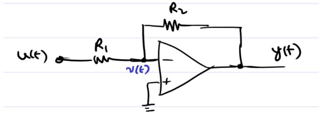
It is common in electronic system design to use op-amps in negative feedback confgurations, as shown below.
In idealized operation, the voltage v(t) at the “-” terminal of the op-amp is assumed to be at “virtual ground”. No current enters or leaves the “-” terminal, hence applying KCL at that terminal results in
the I/O relationship .
A more realistic analysis, however, would represent the internals of the op-amp as shown below:
NOTE: As you go through this question, you may fnd that your derivations and results challenge previous (simplistic) notions you may have about op-amps. That’s what this question is meant to do. (Turn to the next page for the questions.)
Fig. 1: Op-amp in negative feedback configuration. u(t), v(t) and y(t) all refer to the voltages at the corresponding nodes.
3a) Using , the op-amp’s internal circuitry in Fig. 2 can be expressed in state space form as
, with .
Write out expressions (involving R, C, and G) for , and . (3 points)
3b) Find expressions for the eigenvalues of and indicate if the op-amp model can be i) stable, ii) marginally stable and iii) unstable, explaining each answer. Note that R, C and G can only take values > 0, i.e. they cannot be zero or negative. (3 points)
3c) If we use the op-amp model of Fig. 2 in the negative-feedback circuit of Fig. 1, the overall closed-loop circuit can also be written in state-space form as
, with .
Write out expressions for and in terms of R, C, G, and . Note that and are the
same as in 3a), and that the input is now and not . (5 points)
3d) Can the closed-loop system of 3c) be i) stable, ii) marginally stable and iii) unstable? For each one that is possible, write out a condition (i.e., an equation or inequality involving R, C, G, and
Problem 4 (10 points) Observability and Observers [CAN CLOBBER MT2]
Consider the discrete-time state space system
, where T is a time interval (real number > 0).
(This system is exactly the same as the one for the car with piecewise-constant (PWC) acceleration
covered in class. is the PWC acceleration applied to the car, is its position at time tT, and
is its velocity at time tT.)
We augment the above equation with an output equation, i.e., y[t] = p[t].
4a) Find the eigenvalues of A. (1 point)
4b) Suppose u[t] = 0 for all t. Derive expressions for if (i) , and (ii) . (1 point)
4c) Is the system observable? Justify/derive your answer. (1 point)
The remaining question-parts below pertain to designing an observer for the system, i.e., fnding
such that in the observer system below develops into a good approximation of .
The observer is
.
4d) Suppose we set Is it possible to design a stable observer by setting to some appropriate value? (if so, provide and justify such a value; if not, explain why not). (4 points)
4e) Suppose we set Is it possible to design a stable observer by setting to some appropriate
value? (if so, provide and justify such a value; if not, explain why not). (1 point)
4f) Suppose we set
(i) Is it possible to design a stable observer by setting to some appropriate value? Justify your answer.
(ii) Is it possible to design an unstable observer by setting to some appropriate value? Justify your answer. (2 points)
Problem 5 (10 points) PCA and SVD
5a) For each of the following, indicate if it is a valid covariance matrix or not. Justify your answers concretely. (2 points)
5a-i) : VALID INVALID Explanation:
5a-ii) : VALID INVALID Explanation:
5a-iii) : VALID INVALID Explanation:
5a-iv) : VALID INVALID Explanation:
5b) PCA intuition: (2 points) 5b-i) Sketch two straight lines on the 2-d data on the right: one (longer)
indicating the direction of the principal component, and another (shorter) indicating the direction of the 2nd principal component.
5b-ii) The data in the fgure below are in three clusters, ie, in the ellipses with centroids/means of each cluster marked. Assume that each ellipse is
uniformly populated by data points. The major and minor extents of the eliipses are also shown.
Suppose we run a PCA analysis on this data. Sketch lines on the fgure indicating the direction of the principal component (longer) and the 2nd principal component (shorter). Label them 5b-ii).
5b-iii) Now suppose we frst run k-means on the data (with k=3) and succeed in identifying the clusters correctly. We then run PCA separately on each cluster. Sketch lines on each cluster indicating the direction of the principal component (longer line) and the 2nd principal component (shorter) for each. Label them 5b-iii).
5c) Compute the SVD of using the technique illustrated by example in class. Show your calculations clearly. Note: only the full SVD, correctly computed, will receive full credit. Leave numbers like as , i.e., don’t “simplify” them to 1.414! (6 points)
Problem 6 (5 points) k-means
The k-means algorithm has two steps:
- STEP 1: Assign each data point to the cluster/mean that is nearest; and
- STEP 2: Update each cluster’s mean to be the average of the cluster’s data. (If the cluster contains no data, then don’t update the mean).
Run the k-means algorithm manually on the following data:
Each * represents a data point; the circle and diamond indicate the initial means of the k=2 clusters. Indicate the progress of k-means using the following template. ROUND 1, STEP 1 is flled out for you as an illustration. Indicate clearly where the algorithm stops. YOU SHOULD NOT FILL IN ANY STEPS AFTER THE ALGORITHM STOPS.
INIT
circle cluster: mean = -0.5, data = {empty} diamond cluster: mean = -0.25, data = {empty} ROUND 1, STEP 1
circle cluster: data = { empty }
diamond cluster: data = { 0, 0.5, 1, 1.5, 2 }
ROUND 1, STEP 2
circle cluster: mean =
diamond cluster: mean =
ROUND 2, STEP 1
circle cluster: data = { }
diamond cluster: data = { }
ROUND 2, STEP 2
circle cluster: mean =
diamond cluster: mean =
ROUND 3, STEP 1
circle cluster: data = { }
diamond cluster: data = { }
ROUND 3, STEP 2
circle cluster: mean =
diamond cluster: mean =
ROUND 4, STEP 1
circle cluster: data = { }
diamond cluster: data = { }
ROUND 4, STEP 2
circle cluster: mean =
diamond cluster: mean =
ROUND 5, STEP 1
circle cluster: data = { }
Problem 7 (15 points) – LTI systems
7a) Prove that the composition of two LTI systems is LTI. In other words, that if each block in the
fgure below is LTI, then is LTI. You must be clear and precise (and correct) in your
reasoning for full credit. (3 points)
7b) Using reasoning similar to 7a, it is easy to show that the composition of N LTI systems, as
depicted below, is LTI. (2 points)
Suppose all the internal LTI blocks LTI1 to LTIN are identical, with impulse response
Find the impulse response of the composed system, i.e., from Show your reasoning
7c) Given a discrete-time, causal, LTI system with impulse response h[t]. You are not told what h[t] is.
However, you are told that if the input u[t] to the system is chosen to be h[t], then the frst fve samples of the output y[t] are: y[0] = 1, y[1] = 0, y[2] = -2, y[3] = 0, y[4] = 3.
Find two different possible solutions for h[t] (only for t=0, …, 4) that satisfy the above condition. Are other solutions for t=0,…,4 also possible? Justify your answers and arguments clearly and precisely.
(4 points)
7d) Given two discrete-time LTI systems in a feedback loop (6 points)
with , and
Please read through the expressions above for h[t] and very carefully and make sure you
understand them right. Note also that the feedback adds to the input.
7d-i) Assuming that for all t<0, fnd the impulse response of the closed-loop system (i.e.,
from ).
Hint: write out y[t] for t=0 ,…,15 at least (not required, but highly recommended), examine the values and use to devise a general formula or expression for y[t]. Be very careful to avoid mistakes in your calculations (please double and triple-check each step).
7d-ii) Is the closed-loop system BIBO stable or BIBO unstable? If stable, explain why. If unstable,
write out an input u[t] that will make y[t] → as t → .
Problem 8 (20 points) DFT and Interpolation
Given N odd, , with and of size N.
is the DFT matrix of size N, with the (k,l)th entry (numbering from 0) being , where .
8a) Suppose (capital Xi) are
What is ? (write an expression for the entries of ).
Hint: if you apply a) the relation between the DFT matrix and its inverse, and b) the phasor-extracting properties of the DFT, this is a short exercise of a few lines. (4 points)
8c) We saw in class that if are N=2M+1 samples of
i.e., if , with and i=0, …, N-1, then
It is possible to express x(t) exactly in basis-function interpolation form as
Derive an expression for . Show every step of your derivation clearly.
Hint: suggested procedure:
(i) Express (1) using (2) – i.e., eliminate in favour of in (1).
(ii) Then, eliminate in favour of by applying the DFT relationship between and .
(iii) Arrange the expression thus obtained for (1) to ft the form of (3) and identify an expression for . You will fnd the identity
to be very useful. (No need to prove this identity here).
(14 points)
(space for 8c) (this is the last page of the exam)