Reference
R1
Reference
R1 ~ R7
Steel and Non-Ferrous Metal Symbols Chart...R2
Hardness Scale Comparison Chart...R4
Standard of Tapers ...R5
Finished Surface Roughness ...R6
Tolerance Chart for Round Matching Parts...R7
R2
Reference
■
Steel and Non-Ferrous Metal Symbols Chart
●
Carbon Steels
●
High Speed Steels
●
Austenitic Stainless Steels
JIS AISI DIN
S10C 1010 C10 S15C 1015 C15 S20C 1020 C22 S25C 1025 C25 S30C 1030 C30 S35C 1035 C35 S40C 1040 C40 S45C 1045 C45 S50C 1049 C50 S55C 1055 C55
JIS AISI DIN
SKH2 T1 — SKH3 T4 — SKH10 T15 — SKH51 M2 S6-5-2 SKH52 M3–1 — SKH53 M3–2 S6-5-3 SKH54 M4 — SKH56 M36 —
JIS AISI DIN
SUS201 AISI 201
SUS202 AISI 202
SUS301 AISI 301
SUS302 AISI 302
SUS302B AISI 302B
SUS303 AISI 303 DINX10CrNiS189
SUS303Se AISI 303Se
SUS304 AISI 304 DINX5CrNi1810
SUS304L AISI 304L DINX2CrNi1911
SUS304NI AISI 304N
●
Ni-Cr-Mo Steels
●
Cr Steels
●
Cr-Mo Steels
●
Cr-Mo Steels
●
Mn Steels and Mn-Cr Steels for
Structural Use
●
Alloy Tool Steels
●
Grey Cast Iron
●
Nodular Cast Iron
●
Ferritic Stainless Steels
●
Martensitic Stainless Steels
SNCM220 8620 — SNCM240 8640 — SNCM415 — — SNCM420 4320 — SNCM439 4340 — SNCM447 — — SKS11 F2 — SKS51 L6 — SKS43 W2-9 1/2 — SKS44 W2-8 1/2 — SKD1 D3 X210Cr12 SKD11 D2 —
SUS305 AISI 305 DINX5CrNi1812
SUS308 AISI 308
SUS309S AISI 309S
SUS310S AISI 310S
SUS316 AISI 316 DINX5CrNiMo17122
SUS316L AISI 316L DINX2CrNiMo17132
SUS316N AISI 316N
SUS317 AISI 317
DINX2CrNiMo18164
SUS317L AISI 317L
SUS321 AISI 321
SUS347 AISI 347 DINX6CrNiNb1810
SUS384 AISI 384 SCr415 — — SCr420 — — SCr430 5130 34Cr4 SCr435 5135 37Cr4 SCr440 5140 41Cr4 SCr445 5147 — FC100 20 GG-10 FC150 25 GG-15 FC200 30 GG-20 FC250 35 GG-25 FC300 40 GG-30 FC350 50 GG-35 SCM415 — — SCM420 — — SCM430 4130 — SCM435 4135 34CrMo4 SCM440 4140 42CrMo4 SCM445 4145 — FCD400 — GGG-40 FCD450 60/40/ 8 GGG-40.3 FCD500 65/45/12 GGG-50 FCD600 80/55/06 GGG-60 FCD700 100/70/03 GGG-70 SMn420 1522 — SMn433 1536 — SMn438 1541 — SMn443 1541 — SMnC420 — — SMnC443 — — SK1 W1-13 — SK2 W1-11 1/2 — SK3 W1-10 C105W1 SK4 W1-9 — SK5 W1-8 C80W1 SK6 W1-7 C80W1 SK7 — C70W2
SUS405 AISI 405 DINX6CrAl13
SUS429 AISI 429
SUS430 AISI 430 DINX6Cr17
SUS430F AISI 430F DINX12CrMoS17
SUS434 AISI 434
SUS403 AISI 403
SUS410 AISI 410 DINX10Cr13
SUS416 AISI 416
SUS420JI AISI 420 DINX20Cr13
SUS420F AISI 420F
SUS431 AISI 431 DINX20CrNi172
SUS440A AISI 440A
SUS440B AISI 440B
SUS440C AISI 440C
●
Heat Resisting Steels
●
Ferritic Heat Resisting Steels
●
Martensitic Heat Resisting Steels
SUH31 SUH35 SUH36 SUH37 SUH38 SUH309 AISI 309
SUH310 AISI 310 DINCrNi2520
SUH330 AISI 330
SUH21 DINCrAl1205
SUH409 AISI 409 DINX6CrTi12
SUH446 AISI 446 SUH1 SUH3 SUH4 SUH11 SUH600
Reference
Reference
R3
Reference
■
Steel and Non-Ferrous Metal Symbols Chart
●
Classifications and Symbols of Steels
●
Non-Ferrous Metals
Class Material Symbol Symbol's Rationale
Structural Steels
Rolled Steels for welded structures SM "M" for "Marine" - Usually used in welded marine structures
Re-rolled Steels SRB "R" for "Re-rolled" and "B" for "Bar"
Rolled Steels for general structures SS "S" for "Steel" and for "Structure"
Light gauge sections for general structures SSC "C" for "Cold"
Steel
Sheets Hot rolled mild steel sheets / plates in coil form SPH "P" for "Plate" and "H" for "Hot"
Steel
Tubes
Carbon steel tubes for piping SGP "GP" for "Gas Pipe"
Carbon steel tubes for boiler and heat exchangers STB "T" for "Tube" and "B" for "Boiler"
Seamless steel tubes for high pressure gas cylinders STH "H" for "High Pressure"
Carbon steel tubes for general structures STK "K" for "Kozo"- Japanese word meaning "structure"
Carbon steel tubes for machine structural uses STKM "M" for "Machine"
Alloy steel tubes for structures STKS "S" for "Special"
Alloy steel tubes for pipings STPA "P" for "Piping" and "A" for "Alloy"
Carbon steel tubes for pressure pipings STPG "G" for "General"
Carbon steel tubes for high temperature pipings STPT "T" for " Temperatures"
Carbon steel tubes for high pressure pipings SPS "S" after "SP" is abbreviation for "Special"
Stainless steel tubes for pipings SUS-TP "T" for "Tube" and "P" fpr "Piping"
Steel
for
Machine
Structures
Carbon steels for machine structural uses SxxC "C" for "Carbon"
Aluminium Chromium Molybdenum steels SACM "A" for "Al", "C" for "Cr" and "M" for "Mo"
Chromium Molybdenum steels SCM "C" for "Cr" and "M" for "Mo"
Chromium steels SCr "Cr" for "Chromium"
Nickel Chromium steels SNC "N" for "Nickel" and "C" for "Chromium"
Nickel Chromium Molybdenium steels SNCM "M" for "Molybdenium"
Manganese steels for structural use
Manganese Chromium steels SMnSMnC "Mn" for "Manganese""C" for "Chromium"
Special
S
teels
Carbon tool steels SK "K" for "Kogu"- Japanese word meaning "tool"
Hollow drill steels SKC "C" for "Chisel"
Alloy tool steel SKSSKD
SKT
"S" for "Special" "D" for "Die"
"T" for "Tanzo"- Japanese word for "forging"
High speed tool steels SKH "H" for "High speed"
Free cutting sulfuric steels SUM "M" for "Machinability"
High Carbon Chromium bearing steels SUJ "J" for "Jikuuke"- Japanese word meaning "bearing"
Spring steels SUP "P" for "Spring"
Stainless steels SUS "S" after "SU" is abbreviation for "Stainless"
Heat-resistant steels SUH "U" for "Special Usage" and "H" for "Heat"
Heat-resistant steel bars SUHB "B" for "Bar"
Heat-resistant steel sheets SUHP "P" for "Plate"
Forged Steels
Carbon steel forgings for general use SF "F" for "Forging"
Carbon steel booms and billets for forgings SFB "B" for "Billet"
Chromium Molybdenium steel forgings SFCM "C" for "Chromium" and "M" for "Molybdenium"
Nickel Chromium Molybdenium steel forgings SFNCM "N" for "Nickel"
Cast
Irons
Grey cast irons FC "F" for "Ferrous" and "C" for "Casting"
Spherical graphite / Ductile cast irons FCD "D" for "Ductile"
Blackheart malleable cast irons FCMB "M" for "Malleable" and "B" for "Black"
Whiteheart malleable cast irons FCMW "W" for "White"
Pearlite malleable cast irons FCMP "P" for "Pearlite"
Cast
Steels
Carbon cast steels SC "C" for "Casting"
Stainless cast steels SCS "S" for "Stainless"
Heat-resistant cast steels SCH "H" for "Heat"
High Manganese cast steels SCMnH "Mn" for "Manganese" and "H" for "High"
Tool Steels Stainless S teels Heat-resistant Steels
Class Material Symbol
Copper
and
Copper
A
lloys Copper and Copper alloys - Sheets, plates and strips
CxxxxP CxxxxPP CxxxxR
Copper and Copper alloys - Welded pipes and tubes
CxxxxBD CxxxxBDS CxxxxBE CxxxxBF Aluminium a nd Aluminium A
lloys Aluminium and Al alloys- Sheets, plates and strips
AxxxxP AxxxxPC Aluminium and Al alloys
- Rods, bars and wires
AxxxxBE AxxxxBD AxxxxW Aluminium and Al alloys - Extruded shapes AxxxxS
Aluminium and Al alloy forgings AxxxxFD
AxxxxFH
Magnesium Alloys
Magnesium alloy sheets and plates MP
Nickel Alloys
Nickel-Copper alloy sheets and plates NCuP
Nickel-Copper alloy rods and bars NCuB
Wrought Titanium
Titanium rods and bars TB
Castings
Brass castings YBsCx
High strength Brass castings HBsCx
Bronze castings BCx
Phosphorus Bronze castings PCBx
Aluminium Bronze castings AlBCx
Aluminium alloy castings AC
Magnesium alloy castings MC
Zinc alloy die castings ZDCx
Aluminium alloy die castings ADC
Magnesium alloy die castings MDC
White metals WJ
Aluminium alloy castings for bearings AJ Copper-Lead alloy castings for bearings KJ
R4
Reference
■
Hardness Scale Comparision Chart
Brinell Hardness (HB) 3,000kgf Rockwell Hardness Vickers Hardness 50kgf Shore Hardness Traverse Rupture Strength (kg/mm2) "A" Scale 60kgf (Brale) "B" Scale 100kgf (1/10" Ball) "C" Scale 150kgf (Brale) "D" Scale 100kgf (Brale) — 85.6 — 68.0 76.9 940 97 — — 85.3 — 67.5 76.5 920 96 — — 85.0 — 67.0 76.1 900 95 — 767 84.7 — 66.4 75.7 880 93 — 757 84.4 — 65.9 75.3 860 92 — 745 84.1 — 65.3 74.8 840 91 — 733 83.8 — 64.7 74.3 820 90 — 722 83.4 — 64.0 73.8 800 88 — 712 — — — — — — — 710 83.0 — 63.3 73.3 780 87 — 698 82.6 — 62.5 72.6 760 86 — 684 82.2 — 61.8 72.1 740 — — 682 82.2 — 61.7 72.0 737 84 — 670 81.8 — 61.0 71.5 720 83 — 656 81.3 — 60.1 70.8 700 — — 653 81.2 — 60.0 70.7 697 81 — 647 81.1 — 59.7 70.5 690 — — 638 80.8 — 59.2 70.1 680 80 — 630 80.6 — 58.8 69.8 670 — — 627 80.5 — 58.7 69.7 667 79 — 601 79.8 — 57.3 68.7 640 77 — 578 79.1 — 56.0 67.7 615 75 — 555 78.4 — 54.7 66.7 591 73 210 534 77.8 — 53.5 65.8 569 71 202 514 76.9 — 52.1 64.7 547 70 193 495 76.3 — 51.0 63.8 528 68 186 477 75.6 — 49.6 62.7 508 66 177 461 74.9 — 48.5 61.7 491 65 170 444 74.2 — 47.1 60.8 472 63 162 429 73.4 — 45.7 59.7 455 61 154 415 72.8 — 44.5 58.8 440 59 149 401 72.0 — 43.1 57.8 425 58 142 388 71.4 — 41.8 56.8 410 56 136 375 70.6 — 40.4 55.7 396 54 129 363 70.0 — 39.1 54.6 383 52 124 352 69.3 (110.0) 37.9 53.8 372 51 120 341 68.7 (109.0) 36.6 52.8 360 50 115 331 68.1 (108.5) 35.5 51.9 350 48 112 Brinell Hardness (HB) 3,000kgf Rockwell Hardness Vickers Hardness 50kgf Shore Hardness Traverse Rupture Strength (kg/mm2) "A" Scale 60kgf (Brale) "B" Scale 100kgf (1/10" Ball) "C" Scale 150kgf (Brale) "D" Scale 100kgf (Brale) 321 67.5 (108.0) 34.3 50.1 339 47 108 311 66.9 (107.5) 33.1 50.0 328 46 105 302 66.3 (107.0) 32.1 49.3 319 45 103 293 65.7 (106.0) 30.9 48.3 309 43 99 285 65.3 (105.5) 29.9 47.6 301 — 97 277 64.6 (104.5) 28.8 46.7 292 41 94 269 64.1 (104.0) 27.6 45.9 284 40 91 262 63.6 (103.0) 26.6 45.0 276 39 89 255 63.0 (102.0) 25.4 44.2 269 38 86 248 62.5 (101.0) 24.2 43.2 261 37 84 241 61.8 100.0 22.8 42.0 253 36 82 235 61.4 99.0 21.7 41.4 247 35 80 229 60.8 98.2 20.5 40.5 241 34 78 223 — 97.3 (18.8) — 234 — — 217 — 96.4 (17.5) — 228 33 74 212 — 95.5 (16.0) — 222 — 72 207 — 94.6 (15.2) — 218 32 70 201 — 93.8 (13.8) — 212 31 69 197 — 92.8 (12.7) — 207 30 67 192 — 91.9 (11.5) — 202 29 65 187 — 90.7 (10.0) — 196 — 63 183 — 90.0 (9.0) — 192 28 63 179 — 89.0 (8.0) — 188 27 61 174 — 87.8 (6.4) — 182 — 60 170 — 86.8 (5.4) — 178 26 58 167 — 86.0 (4.4) — 175 — 57 163 — 85.0 (3.3) — 171 25 56 156 — 82.9 (0.9) — 163 — 53 149 — 80.8 — — 156 23 51 143 — 78.7 — — 150 22 50 137 — 76.4 — — 143 21 47 131 — 74.0 — — 137 — 46 126 — 72.0 — — 132 20 44 121 — 69.8 — — 127 19 42 116 — 67.6 — — 122 18 41 111 — 65.7 — — 117 15 39
1) Figures within the ( ) are not commonly used 2) Rockwell A, C and D scales utilises a diamond brale
R5
Reference
■
Standard of Tapers
●
Morse Taper
Reference
Morse Taper Number Taper* Taper Angle (α˚) Taper Tang Shape D d D1 + (Estimated) d1+ (Estimated)l
1 (Max)l
2 (Max) d2 (Max) b C (Max) e (Max) R r 0 19.2121 0.05205 1˚29'27" 9.045 3 9.2 6.1 56.5 59.5 6.0 3.9 6.5 10.5 4 1 Fig 1 1 20.0471 0.04988 1˚25'43" 12.065 3.5 12.2 9.0 62.0 65.5 8.7 5.2 8.5 13.5 5 1.2 2 20.0201 0.04995 1˚25'50" 17.780 5 18.0 14.0 75.0 80.0 13.5 6.3 10 16 6 1.6 3 19.9221 0.05020 1˚26'16" 23.825 5 24.1 19.1 94.0 99.0 18.5 7.9 13 20 7 2 4 19.2451 0.05194 1˚29'15" 31.267 6.5 31.6 25.2 117.5 124.0 24.5 11.9 16 24 8 2.5 5 19.0021 0.05263 1˚30'26" 44.399 6.5 44.7 36.5 149.5 156.0 35.7 15.9 19 29 10 3 6 19.1801 0.05214 1˚29'36" 63.348 8 63.8 52.4 210.0 218.0 51.0 19 27 40 13 4 7 19.2311 0.05200 1˚29'22" 83.058 10 83.6 68.2 286.0 296.0 66.8 28.6 35 54 19 5 Morse Taper Number Taper* Taper Angle (α˚) Taper Thread Shape D d D1 + (Estimated) d1+ (Estimated)l
1 (Max)l
2 (Max) d2 (Max) d3 K (Max) t (Max) r 0 19.2121 0.05205 1˚29'27" 9.045 3 9.2 6.4 50 53 6 — — 4 0.2 Fig 2 1 20.0471 0.04988 1˚25'43" 12.065 3.5 12.2 9.4 53.5 57 9 M 6 16 5 0.2 2 20.0201 0.04995 1˚25'50" 17.780 5 18.0 14.6 64 69 14 M10 24 5 0.2 3 19.9221 0.05020 1˚26'16" 23.825 5 24.1 19.8 81 86 19 M12 28 7 0.6 4 19.2541 0.05194 1˚29'15" 31.267 6.5 31.6 25.9 102.5 109 25 M16 32 9 1 5 19.0021 0.05263 1˚30'26" 44.399 6.5 44.7 37.6 129.5 136 35.7 M20 40 9 2.5 6 19.1801 0.05214 1˚29'36" 63.348 8 63.8 53.9 182 190 51 M24 50 12 4 7 19.2311 0.05200 1˚29'22" 80.058 10 86.6 70.0 250 260 65 M33 80 18.5 5* The fractional values are the taper standards.
+Diameters (D1) and (d1) are calculated from the values of (D) and other values of the taper.
(Values are rounded up to one decimal place)
●
Bottle Grip Taper
●
Bottle Grip Taper
●
American Standard Taper (National Taper)
●
American Standard Taper (National Taper)
Taper No. D1 D2 t1 t2 t3 t4 t5 d1 (Standard) d2 d3 d4 L
l
2l
3l
4 g b1 t7 Reference ShapeBT40
63 53 25 10 16.6 2 2 44.45 19 17 14 65.4 30 8 21 M16 16.1 22.6 25.3 70 Fig 1BT45
85 73 30 12 21.2 3 3 57.15 23 21 17.5 82.8 38 9 26 M20 19.3 29.1 33.1 70BT50
100 85 35 15 23.2 3 3 69.85 27 25 21 101.8 45 11 31 M24 25.7 35.4 40.1 90BT60
155 135 45 20 28.2 3 3 107.95 33 31 26.5 161.8 56 12 34 M30 25.7 60.1 60.7 110 d5l
1 (Units in mm) (Units in mm)Taper No. Nominal Diameter D d1 L
l
1l
2l
3 g a t b Shape30
11/4" 31.750 17.40 – 0.29 – 0.36 70 20 24 50 1/2" 1.6 15.9 16 Fig 240
13/4" 44.450 25.32 – 0.30 – 0.384 95 25 30 60 5/8" 1.6 15.9 22.550
23/4" 69.850 39.60 – 0.31 – 0.41 130 25 45 90 1" 3.2 25.4 3560
41/4" 107.950 60.20 – 0.34 – 0.46 210 45 56 110 11/4" 3.2 25.4 60 r R 8˚18' α˚ a C b ød 1 ød 2 øD 1 øD , , K r t S α˚ a ød 3 ød 2 ød 1 øD 1 øD 60˚ L g t1 t5 t2 t3 t4 D 1 D 2 d 5 60˚ d2 d3 d 4 b1 A Face 7/24 Taper b 1 ,,,, ,,,, 60˚ ød 1 øD ø t L a b , , 7/24 Taper Fig 1 Fig 2(Fig 1) With Tang Type (Fig 2) Drawing Thread Type
R6
Reference
Reference
■
Finished Surface Roughness
●
Types of Surface Roughness Measurements
Types Symbol Method of Determination Descriptive Figure
Maximum
H
eight
Ry
This is the value (expressed in µm) measured from the deepest valley to the highest peak of the
reference line,
l
, extractedfrom the profile. (Disregard unusually high peaks and deep valleys as they are considered as flaws.) Ten-point M ean R oughness Rz
From the profile, extract a portion to be the reference
line,
l
.Select the 5 highest peak and 5 deepest valleys. Measure the distance between the two lines and express it in µm.
Calculated
Roughness Ra
This method is to obtain a center line between the peaks and valleys within
the reference line,
l
.Fold along the center line to superimpose the valleys against the peaks. (Shaded portions with dashed outline on the right figure). Take the total shaded area and divided it
by
l
in µm. Rp Ry Rv m Yp 1 Yp 2 Yp 3 Yp 4 Yp 5 Yv 1 Yv 2 Yv 3 Yv 4 Yv 5 m Ra Roughness Curve f ,, ,, ,, ,, , , ,, ,, ,, ,, ,, ,, , , ,, ,,Designated values of the above types of surface roughness, standard reference length values and the triangular symbol classifications are shown on the table on the right.
Designated values for Ry Designated values for Rz Designated values for Ra Standard reference length values,
l
(mm) Triangular Symbols (0.05S) 0.1S 0.2S 0.4S (0.05Z) 0.1Z 0.2Z 0.4Z (0.013a) 0.025a 0.05a 0.10a — ▲ ▲▲▲▲▲▲▲ 0.8S 0.8Z 0.20a 0.25 1.6S 3.2S 6.3S 1.6Z 3.2Z 6.3Z 0.40a 0.80a 1.6a 0.8 ▲▲▲▲▲▲ 12.5S (18S) 25S 12.5Z (18Z) 25Z 3.2a 6.3a 2.5 ▲▲▲▲ (35S) 50S (70S) 100S (35Z) 50Z (70Z) 100Z 12.5a 25a — ▲ ▲ (140S) 200S (280S) 400S (560S) (140Z) 200Z (280Z) 400Z (560Z) (50a) (100a) — —Remarks: The designated values in the brackets do not apply unless otherwise stated.
R7
Reference
■
Tolerance Chart for Round Matching Parts
●
Tolerance for Shank Sizes
●
Tolerance for Hole Sizes
Reference
Diameter, D(mm)
Tolerance Class (µm)
>D ≤D b9 c9 d8 d9 e7 e8 e9 f6 f7 f8 g5 g6 h5 h6 h7 h8 h9 – 3 –140–165 –60–85 –20–34 –45–20 –24–14 –14–28 –14–39 –12–6 –16–6 –20–6 –2–6 –2–8 –40 –60 –100 –140 –250 3 6 –140–170 –100–70 –30–48 –60–30 –20–32 –20–38 –20–50 –10–18 –10–22 –10–28 –4–9 –12–4 –50 –80 –120 –180 –300 6 10 –150–186 –80 –116 –40 –62 –40 –76 –25 –40 –25 –47 –25 –61 –13 –22 –13 –28 –13 –35 –5 –11 –5 –14 0 –6 0 –9 0 –15 0 –22 0 –36 10 14 –150 –193 –95 –138 –50 –77 –50 –93 –32 –50 –32 –59 –32 –75 –16 –27 –16 –34 –16 –43 –6 –14 –6 –17 0 –8 0 –11 0 –18 0 –27 0 –43 14 18 18 24 –160 –212 –110 –162 –65 –98 –65 –117 –40 –61 –40 –73 –40 –92 –20 –33 –20 –41 –20 –53 –7 –16 –7 –20 0 –9 0 –13 0 –21 0 –33 0 –52 24 30 30 40 –170–232 –120–182 –80 –119 –80 –142 –50 –75 –50 –89 –50 –112 –25 –41 –25 –50 –25 –64 –9 –20 –9 –25 0 –11 0 –16 0 –25 0 –39 0 –62 40 50 –180–242 –130–192 50 65 –190–264 –140–214 –110 –146 –100 –174 –60 –90 –60 –106 –60 –134 –30 –49 –30 –60 –30 –76 –10 –23 –10 –29 0 –13 0 –19 0 –30 0 –46 0 –74 65 80 –200–274 –150 –224 80 100 –220–307 –170–257 –120 –174 –120 –207 –72 –107 –72 –126 –72 –159 –36 –58 –36 –71 –36 –90 –12 –27 –12 –34 0 –15 0 –22 0 –35 0 –54 0 –87 100 120 –240–327 –180–267 120 140 –260–360 –200 –300 –145 –208 –145 –245 –85 –125 –85 –148 –85 –185 –43 –68 –43 –83 –43 –106 –14 –32 –14 –39 0 –18 0 –25 0 –40 0 –63 0 –100 140 160 –280–380 –210 –310 160 180 –310–410 –230–330 180 200 –340–455 –240–355 –170 –242 –170 –285 –100 –146 –100 –172 –100 –215 –50 –79 –50 –96 –50 –122 –15 –35 –15 –44 0 –20 0 –29 0 –46 0 –72 0 –115 200 225 –380–495 –260 –375 225 250 –420–535 –280 –395
Diameter, D(mm)
Tolerance Class (µm)
>D ≤D B10 C9 C10 D8 D9 D10 E7 E8 E9 F6 F7 F8 G6 G7 H6 H7 H8 – 3 +180+140 +85 +60 +100 +60 +34 +20 +45 +20 +60 +20 +24 +14 +28 +14 +39 +14 +12 +6 +16 +6 +20 +6 +8 +2 +12 +2 +6 0 +10 0 +14 0 3 6 +188+140 +100+70 +118+70 +30+48 +60+30 +78+30 +32+20 +38+20 +50+20 +18+10 +22+10 +28+10 +12+4 +16+4 +80 +120 +180 6 10 +208+150 +116+80 +138+80 +40+62 +76+40 +98+40 +40+25 +47+25 +61+25 +22+13 +28+13 +35+13 +14+5 +20+5 +90 +150 +220 10 14 +220 +150 +138 +95 +165 +95 +77 +50 +93 +50 +120 +50 +50 +32 +59 +32 +75 +32 +27 +16 +34 +16 +43 +16 +17 +6 +24 +6 +11 0 +18 0 +27 0 14 18 18 24 +244 +160 +162 +110 +194 +110 +98 +65 +117 +65 +149 +65 +61 +40 +73 +40 +92 +40 +33 +20 +41 +20 +53 +20 +20 +7 +28 +7 +13 0 +21 0 +33 0 24 30 30 40 +270+170 +182 +120 +220 +120 +119 +80 +142 +80 +180 +80 +75 +50 +89 +50 +112 +50 +41 +25 +50 +25 +64 +25 +25 +9 +34 +9 +16 0 +25 0 +39 0 40 50 +280+180 +192 +130 50 65 +310+190 +214+140 +260+140 +146 +146 +174 +100 +220 +146 +90 +60 +106 +60 +134 +60 +49 +30 +60 +30 +76 +30 +29 +10 +40 +10 +19 0 +30 0 +46 0 65 80 +320+200 +224+150 80 100 +360+220 +257 +170 +310 +170 +174 +120 +207 +120 +260 +120 +107 +72 +126 +72 +159 +72 +58 +36 +71 +36 +90 +36 +34 +12 +47 +12 +22 0 +35 0 +54 0 100 120 +380+240 +267 +180 120 140 +420+260 +300+200 +360+200 +208 +145 +245 +145 +205 +145 +125 +85 +148 +85 +185 +85 +68 +43 +83 +43 +106 +43 +39 +14 +54 +14 +25 0 +40 0 +63 0 140 160 +440+280 +310+210 160 180 +470+310 +330 +230 180 200 +525+340 +355+240 +425+240 +242 +170 +285 +170 +355 +170 +146 +100 +172 +100 +215 +100 +79 +50 +96 +50 +122 +50 +44 +15 +61 +15 +29 0 +46 0 +72 0 200 225 +565+380 +375+260 225 250 +605+420 +395 +280 H9 H10 +25 0 +40 0 +30 0 +48 0 +36 0 +58 0 +43 0 +70 0 +52 0 +84 0 +62 0 +100 0 +74 0 +120 0 +87 0 +140 0 +100 0 +160 0 +115 0 +185 0 +230 +130 +270 +150 +320 +180 +390 +230 +370 +210 +465 +280 +445 +260
T1
Tu
r
n
in
g
Turning Guidance
T1 ~ T8
Selecting Cutting Conditions & Cutting Resistance ...T2
Influences of Cutting Edge Geometries...T3
General Guide Lines for Turning Tools ...T4
Tool Life ...T5
Tool Failures and Their Counter-Measures...T6
Analysis of Chip Control on Turning ...T7
Factors on Chip Control & Their Influences ...T8
T2
Tu
r
n
in
g
Turning Guidance
■
Selecting Cutting Conditions & Cutting Resistance
<
Selection Of Cutting Conditions
>
●
Cutting Conditions &
Their Influence
●
Selecting Cutting
Parameters
●
Three Component
Forces Of Cutting
Resistance
●
Factors Affecting
Cutting Resistance
●
Determination Of
Cutting Resistance
●
Determination Of
Power Requirement
N : Work Rotating speed (rpm)
V : Cutting speed (m/min)
f : Feedrate (mm/rev)
d : Depth of cut (mm)
D: Workpiece diameter (mm)
N : Spindle Speed (rpm)
N = __________ V : Cutting Speed (m/min) D : Work Diameter (mm)
π : 3.14
1000 x V
πx D
If extracting the Cutting Speed from the Rotating Speed:
π x D x N 1000
Calculating the actual Table Feed (F)
Finally, Calculating the actual Cutting Time (T) in mins.
Calculation of Cutting Speed, Table Feed & Cutting Time
Tool Materials and Cutting Speed Ratio
HSS Carbide Coated Cermet Ceramic 1 3~6 5~15 5~10 10~25
Turned Casting & Continuous Interuppted
Surface Forging Faces Machining Machining
1 0.70 1 0.70
Speed Work Efficiency, Tool Life, Cutting Power Consumption & Surface Roughness
Depth of Cut Working Efficiency, Chip Control, Cutting Power Consumption & Dimensional Accuracy Feed Work Efficiency, Chip Control, Tool Life, Cutting Power Consumption & Surface Roughness
Item Influencing Matters
<
Cutting Resistance
>
Three Component Forces:P1: Principal or Tangential Component
Force
P2: Feed Component Force
P3: Back Component Force
Determination of the Cutting Resistance
P1= Ps x q
H = ____W 0.75
1. Workpiece Low Tensile Strength High 2. Cutting Area Small Cutting Area Large 3. Cutting speed High Cutting Speed Low
4. Rake Angle Large Rake Angle Small
(Positive) (Negative)
5. Approach Angle Small Approach angle Large
Factors Influencing Cutting Resistance
Relation Between Tensile Strength & Cutting Resistance
Tensile Strength (kg/mm2) 30~40 40~50 50~60 60~70 70~80 90~100
Cutting Resistance Ratio 1 1.10 1.18 1.29 1.45 1.70
Cutting Area & Cutting Resistance
Rake Angle & Cutting Resistance
Cutting Speed & Cutting Resistance
Speed Ratio Related to Surface and Machining Conditions of The Work
W = _________V.f.d.Ps
6.12 x 10³.η
Calculating Rotating speed given the Cutting speed:
The symbols are as described in the above.
L F T = _____
F = f x N Where F is in mm/min
Where L is the total cutting length V = __________ Normal Steel : 250~300 kg/mm2 Cast Iron : 150kg/mm2 Approximate Ps value W : Power Requirement (kW) V : Speed (m/min) f : Feedrate (mm/rev) d : Depth of Cut (mm) η: Mechanical Efficiency H : Required Horsepower (HP) P1: Cutting Resistance (kg) Ps: Specific Cutting Resistance (kg/mm2)
q: Area of the chip (mm2)
Determination of Power Requirement
<
<
<
<
<
>
>
>
>
>
Factor Decrease < Cutting Resistance > Increase
------T3
Tu
r
n
in
g
Turning Guidance
Chip Flow Direction
●
Influence Of the Nose
Radius :
*Nose Radius & 3 Component Forces
*Nose Radius & Strength
■
Influences of Cutting Edge Geometries
●
Edge Forms & Their
Influences
Kind Of Edge Forms
1. Back Rake 2. Top or Side Rake 3. Clearance Angle 4. Trail Angle 5. Approach Angle 6. Nose Radius
Strength Of Cutting Edge Cutting Edge Temperature Cutting Resistance Cutting Ability Tool Life Surface Finished Chatter
Relation Between Rake Angle (α°) and Cutting Resistance
Approach Angle and Chip Thickness
Approach Angle and Three Component Forces
Work Material: SCM440 (Hs38) Insert: TNGA220412 Conditions: V= 100m/min f = 0.45 mm/rev d = 4mm
Chip Thickness and Specific Cutting Resistance for Carbon Steels.
Nose Radius and Three Component Forces
Work Material : SCM440 (Hs38) Insert: TNGA 2204 Holder: PTGNR2525-43 Conditions : V = 100m/min d = 4 mm f = 0.45 mm/rev
Relation Between Nose Radius and Strength
Workpiece : Grooved Material (Hs38) Conditions : V=100m/min
Insert : SNGA 1204 ST10P d= 2 mm
Holder : PSBNR2525-43 f = 0.2 mm/rev
●
Influence Of
The Approach Angle :
*Relation To The Undeformed Chip Thickness.
*Chip Thickness & Specific Cutting Resistance.
*Approach Angle & 3 Component Forces.
●
Relation Between Rake
Angle & Cutting
Resistance
●
●
●
●
●
●
●
●
●
●
●
●
●
●
●
●
●
●
●
●
●
●
●
●
●
●
●
●
T4
Tu
r
n
in
g
Turning Guidance
■
General Guide Lines for Turning Tools
●
Surface Roughness
●
Growth Of The Built-Up
Edge & Its Remedies
●
Different Edge
Treatments & Their
Effects
●
Factors That Cause
Chattering & Some Of
Its Remedies
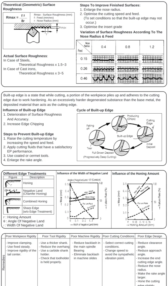
Theoretical (Geometric) Surface Roughness
Steps To Improve Finished Surfaces:
1. Enlarge the nose radius.
2. Optimise the cutting speed and feed.
(To set conditions so that the built-up edge may not occur.)
3. Optimise the insert grade
Variation of Surface Roughness According To The Nose Radius & Feed
Rmax : Surface Roughness (mm) f : Feed (mm/rev)
r : Nose Radius (mm)
Rmax = ____f 2 8r
Built-up edge is a state that while cutting, a portion of the workpiece piles up and adheres to the cutting edge due to work hardening. As an excessively harder degenerated substance than the base metal, the deposited material than acts as the cutting edge.
Influence of Built-up Edge
Steps to Prevent Built-up Edge
1. Raise the cutting temperature by increasing the speed and feed.
2. Apply cutting fluids that have a satisfactory EP performance.
3. Use coated or cermet tools. 4. Enlarge the rake angle.
Different Edge Treatments Influence of the Width of Negative Land Influence of the Honing Amount
r : Honing Amount
θ : Angle Of Negative Land l: Width Of Negative Land
Remedies
1. Deterioration of Surface Roughness And Accuracy.
2. Increase Edge Chipping
Cycle of Built-up Edge
Poor Workpiece Rigidity Poor Tool Rigidity Poor Machine Rigidity Poor Cutting Conditions Poor Edge Design
- Improve clamping. - Use a thicker shank. - Reduce backlash in - Select correct cutting - Reduce clearance
- Use fixed steady. - Reduce the overhang. the main spindle conditions. angle.
- Improve rigidity of the - Use a carbide shank Bearing - Change speed to - Reduce approach
tail center. holder. - Eliminate backlash avoid the sympathetic angle.
- Check that toolholder in machine slides vibration point. - Increase the end
is held properly. cutting edge angle.
- Reduce the nose radius.
- Make the rake angle larger.
- Hone the cutting edge slightly. Figure Description
(Chamfer Honing)
(w/o Edge Treatment) Honing
Negative Land
Combined Honing Sharp Edge
Actual Surface Roughness:
In Case of Steels,
Theoretical Roughness x 1.5~3 In Case of Cast irons,
T5
Tu
r
n
in
g
Turning Guidance
■
Tool Life
●
Wear Process Curve
●
Life Curve (V-T Lines)
●
Tool Life Equation
●
Alternative Tool Life
Criteria
Initial wear is very fast. It then evens out to a more gradual pattern until a limit is reached. From that limit point, the wear increases substantially. VB : Width of Flank Wear (Mean) VC : Maximum Wear of Nose Radius VN : Notch Wear
Crater wear is more progressive, there is no sudden breakdown pattern.
Flank Wear Crater Wear
At four speeds V1, V2, V3 and V4, the relative tool lives for a given flank wear VB or crater KT are indicated as T1, T2, T3 and T4 respectively, using log-log graph paper.
Flank Wear Flank Wear
Life Curve Wearing Process
VTn = C
V : Cutting speed T : Tool Life n & C : Constants Determined by the Work Material, Tool Material, Tool Design, etc.
Tool Life Equation (Taylor's Equation)
1. When surface finish deteriorates unacceptably. 2. When a fixed amount of tool wear is reached,
(see the right hand table)
3. When work piece dimension is not tolerable. 4. When power consumption reaches a limit. 5. Sparking or chip discolouration and disfiguration. 6. Cutting Time or Number of components produced.
KT : Depth of Crater wear B : Width of land KM : Distance between the centre of the Crater wear and Cutting edge.
Width of flank wear for general life determination for cemented carbides.
Width of Wear (mm) Applications
0.2 Finish Cutting of Nonferrous
Alloys, Fine and Light Cut, etc.
0.4 Cutting of Special Steels and
The Like.
0.7 Normal Cutting of Cast Irons,
Steels, etc.
1~ 1.25 Rough Cutting of Common
T6
Tu
r
n
in
g
Turning Guidance
■
Tool Failures and Their Counter-Measures
●
Characteristic Of Tool Failure
●
Failure & Countermeasures
No. Failure Cause
1~5 6 7 Flank Wear Chipping Partial Fracture Crater Wear
Due to the scratching effect of hard grains contained within the work material. Fine breakages caused by high pressure cutting, chatter and vibration, etc. Due to mechanical impact when an excessive force is applied to the cutting edge. Physical
Failure
Excessive Flank Wear
Excessive Crater Wear
Cutting Edge Chipping
Partial Fracture Of Cutting Edges Built-up Edge Plastic Deformation Cutting Conditions Application Example Basic Counter-measures
Tool Material Recommended Insert Grade:
Steel Cast Iron
Finishing T110A (Cermet) BN250 (CBN)
Rough AC2000 AC500G (Alumina
(Alumina Coated) Coated)
NS260C (Ceramic) Recommended Insert Grade:
Steel Cast Iron
Finishing T110A (Cermet) BN250 (CBN)
Rough AC2000 AC500G (Alumina
Machining (Alumina Coated) Coated)
Tool Material
Recommended Insert Grade:
Steel Cast Iron
Finishing T1200A (Cermet) AC500G (Coated)
Rough AC3000 AC500G (Alumina
Machining (Alumina Coated) Coated)
NS260 (Ceramic)
Recommended Insert Grade:
Steel Cast Iron
Rough Machining AC2000 /AC3000 AC500G (Coated) NS260C (Ceramic)
- Change to high thermal resistant grades.
- Reduce the cutting speed and feed. Tool Material
- Change to a grade which is more adhesion resistant.
- Increase the cutting speed and feed. - Use cutting fluids.
Edge Failure Built-up Edge 8 9 10 11 Plastic Deformation Thermal Crack
Due to a combination of galling and welding between the chips and the top rake. The cutting edge is deformed due to its softening at high temperature. Chemical
Thermal fatigue from the heating and cooling cycle during interrupted cutting. The deposition and adhesion of the hardened work material on the cutting edge.
- Use a more wear-resistant grade Coated Carbide Carbide --> Cermet
{
- Decrease Speed >●Use MU Type Chip Breaker
- Use tougher grades.
For carbides: P10 -> P20 -> P30 K01 -> K10 -> K20 - Use the holder with a larger approach
angle.
- Use a holder with a larger shank size. - Reduce the depth of cut and feedrate. - Use tougher grades.
If carbides: P10 -> P20 -> P30 K01 -> K10 -> K20 - If built-up edge occurs, change to a
less susceptible grade eg. cermets. - Reinforce the cutting edge eg. Honing. - Reduce the rake angle.
- Use a crater-resistant grade. Carbide __ Coated (K--> M--> P) Cermet - Enlarge the rake angle - Select the correct chip breaker - Decrease speed, reduce the
depth of cut and feedrate. Tool Material Tool Material Tool design Tool design Cutting Conditions Tool design
- Increase speed (If there is edge build-up).
Cutting
Conditions ●Edge Treatment : All of our inserts have been honed
in advance.
●Insert : Use UX Type Breaker
●Holder : Use Lever-lock Type Cutting Conditions Tool Material Cutting Conditions Cutting Conditions
Recommended Insert Grades : Cermets
T7
Tu
r
n
in
g
Turning Guidance
■
Analysis of Chip Control on Turning
●
Classification Of Chip Formation & Their Influences
●
Factors To Determine Chip Formation
●
Types Of Chip Breaking
Large <-- Work Deformation --> Small Large <--- Rake Angle ---> Small Slight <--- Depth of cut ---> Excess High <--- Cutting Speed ---> Low
- Cause by the effect of the upward curl only, if the rake is too small. - Chip broken because it
struck against the work end face. - Caused by the
upward curling force when the rake angle is large. - Rolls in without breaking
after striking against the work end face.
- Removed spirally by the mixing of upward and sideways curls. - Strikes against the
flank and breaks. - Occurs if the sideways
curling factor is superior. - Strikes against the flank of
the tool and breaks.
Low speed cutting for Steels and Stainless Steels Fine Cutting for Steels and Cast Irons at Excessively Low Speed
Cutting for General Purpose Cast Irons, Rocks, and Carbonous Materials Normal Cutting
for Steels, Light Alloys, and Alloyed Cast Irons
Flow Type Shear Type Tear Type Crack Type
The swarf cracks before reaching cutting edge,which then separates it from parent work piece body.
●
Formation Of Chips
Shape Categories for Chips
Depth of Cut Excess Slight Remarks A B C D E No Curling Over 50 mm Up to and including 50 mm 1 to 5 Turns
Below 1 Turn Half Turn
Continuous Random Shape
Continuous
Regular Shape Good Good
Excessively Broken Chip
Type A Type B Type C Type D Type E Chip Shape Influence Wear Resistance Chipping O X O O O X O O O X Tool life O O O O O O O O O O O O X X X Finished Surface Quality Machining Part Chips O O O O O X O O X X Power Consumption Cutting Resistance Safety O X O O O O O O X X Overall Evaluation X O X Inferior X: Excellent Excellent O: Superior
Influence Of Chip Shapes
(a) If Outlet Angle η = 0 ° (b) If Outlet Angle η = 15° - Factors: Outlet Angle and Cutting Direction
- Chip Forms According to The Combination of Factors
If n = 0 / Outlet Angle Cutting Direction Upward Only Sideways Only Upward + Sideways Spiral Form Cylindrical Form Conical Form Washer-Like Form If n = 0 Transfer Curled Length
Type A : Twines around the tool and work material, causes the machine to stop, quality impairment on the machined surface or problems in safety. Type B : Causes performance reduction of the chip's automatic transfer system or even edge chipping.
Type E : Causes such troubles as spray of chips, unsatisfactory finished surface due to chattering, chipping of the cutting edges or increase in cutting resistance and heat generation.
●Unsatisfactory chip control:
-●Good chip control : Types C and D
Figure of Chip Breaking Type Meanings
Work Obstructive Type Scroll Type Flank Obstructive Type Side Curl Type Continuous Chip and satisfactory surface finish aA chip is sliced -off at the shear angle
Chip with the appearance of being torn off. The workpiece surface is damaged.
Influence Examples
T8
Tu
r
n
in
g
Turning Guidance
■
Factors on Chip Control & Their Influences
●
Influence On The
Cutting Speed & Feed
●
Influence Of The Feed &
Cutting Depth
●
Influence Of The Nose
Radius
●
Influence Of The Side
Cutting Edge Angle
●
Influence On The Rake
Angle
- The effective range of the chip breaker is reduced with the cutting speed being increased. - At high speeds and small
feedrates, lengthened chips will result.
- At high speeds and large feedrates, packed chips will result. Workpiece : S45C (Hs38) Insert : SNMG120408N-UX Holder : PSBNR2525-43 Cutting Conditions: d = 3 mm Workpiece : S45C (Hs38) Insert : SNMG120408N-UX Holder : PSBNR2525-43 Cutting Conditions: V = 150 m/min Workpiece : S45C (Hs38) Insert : CNMG1204 N-UX Holder : PCLNR2525-43 Cutting Conditions: V = 120 m/min f = 0.3 mm/rev Workpiece : S45C (Hs38) Insert : SNMG120408N-UX Holder: PSBNR2525-43
(Side Cutting edge angle 15°)
PSSNR2525-43
(Side Cutting edge angle 45°)
Cutting Conditions: V = 150 m/min d = 3 mm
- Chips become thicker when the rake angle gets smaller but they are easier to control.
For Small Top Rake Angle (α1) - The shear angle is small (φ1) - The chip is thick (t1)
For Large Top Rake Angle (α2) - The shear angle is large (φ2) - The chip is thin (t2)
- With small depths and small feeds, longer chips will be formed.
- With deeper depths and larger feeds, short chips will result.
- Chips become unsusceptible to breakage when the nose radius is larger and the cutting depth is less. - Chips become thinner as
the nose radius gets larger but their control is poor.
- If the side cutting edge angle becomes larger, the outlet angle and chips become larger and thinner respectively which makes the difficult to control.
M1
Milling
Milling Guidance
M1 ~ M7
Milling Cutter Nomenclature & Clamping Method ...M2
Influences of Cutting Edge Geometries ...M3
Surface Finish...M4
Cutter Size & Number of Teeth ...M5
Power Requirement, Cutting Conditions & Grades Selection....M6
Trouble Shooting Guide for Milling ...M7
M2
Milling
Milling Guidance
■
Milling Cutter Nomenclature & Clamping Method
●
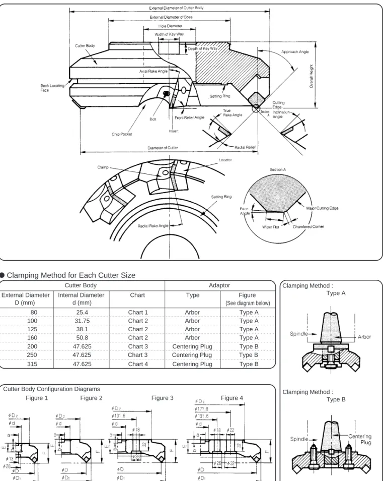
Cutter Parts Name
External Diameter Internal Diameter Chart Type Figure
D (mm) d (mm)
80 25.4 Chart 1 Arbor Type A
100 31.75 Chart 2 Arbor Type A
125 38.1 Chart 2 Arbor Type A
160 50.8 Chart 2 Arbor Type A
200 47.625 Chart 3 Centering Plug Type B
315 47.625 Chart 4 Centering Plug Type B
( D: External Diameter, D1: External Diameter of Body, D2:External Diameter of Boss, d: Hole Diameter,
F: Height, E: Thickness, a: Width of Key Way, b: Depth of Key Way) Cutter Body Configuration Diagrams
Figure 2
Clamping Method : Type A
250 47.625 Chart 3 Centering Plug Type B
Clamping Method : Type B
●
Clamping Method for Each Cutter Size
Cutter Body Adaptor
(See diagram below)
M3
Milling
Milling Guidance
■
Influences of Cutting Edge Geometries
1. Axial Rake Angle 2. Radial Rake Angle
A.R Controls chip removal direction, R.R effects adhesion of the chips and
thrust force etc.
A.A Controls chip thickness and chip removal direction
3. Approach Angle
4. True Rake Angle T.A Effective Rake Angle
5. Inclination Angle
6. Wiper Flat Clearance Angle
7. Clearance Angle
Rake angles can vary from positive to negative (large to small) with typical combinations of positive and negative, positive and positive or negative and negative configurations.
The effect of the large approach angle is to reduce the chip thickness and cutting force.
- With a positive (large) angle, cutting ability and adhesion resistance are improved but the strength of the cutting edge is weakened.
- With negative (small) angle, the strength of the cutting edge is improved but chips will tend to adhere more easily. - With a positive (large) angle, the chip removal is satisfactory
with less cutting resistance but the strength of the corner is weaker.
Disadvantage Advantage
Applications
Typical Cutter (Sample)
Best configuration for chip removal with good cutting action
Only single-sided inserts are available
Suitable for Steels, Cast Irons Stainless Steels, Die Steels, etc.
UFO Type DPG Type DNF Type
General Milling of Steels Low rigidity workpiece Less Cutting Edge Strength
Only single-sided inserts are available. Good Cutting Action
Poor Cutting Action
Milling of Cast Iron
Negative - Positive Cutter Double - Positive Cutter Double - Negative Cutter
●
Combinations Of Principal Angles & Their Features
Description Code Functions Influences
Ready Chart for Inclination Angles
Example in using the above chart : Given: A(Axial Rake Angle) = +10°
R(Radial Rake Angle) = -30° C(Approach Angle) = 60°
Example in using the above chart: Given: A(Axial Rake Angle) = -10°
R(Radial Rake Angle) = +15° C(Approach Angle) = 25°
Solution: I (Inclination Angle) taken from the chart is = -15°
Ready Chart for True Rake Angles
True Rake Angle T Inclination Angle I
●
Various Cutting Angles & Their Functions
I.A Controls chip removal direction
F.A Controls surface finish Controls edge strength, tool life and chattering, etc
A smaller clearance angle will produce a better surface finish.
Solution: T (True Rake Angle) taken from the chart is = -8°
Formula: tan I = tan A.cos C - tan R.sin C Formula: tan T = tan R.cos C + tan A.sin C
: Chip removal direction : Direction of cutter
rotation
Economical using double sided inserts. Chip forms Workpiece: SCM435 Condition : V= 130m/min f = 0.23 mm/tooth d = 3 mm A.R : Axial Rake angle R.R : Radial Rake angle A.A : Approach angle The effects of the various angle configurations with relation to chip formation and chip removal.
M4
Milling
Milling Guidance
■
Surface Finish
b. Radial Run-Out of The Peripheral Cutting Edges
A difference between the maximum and minimum cutting edge positions projected in the radial direction, when rotating with reference at the cutter center.
●
Accuracy on Run-Out of teeth and Surface Finish
The cutting edges of a cutter with multiple cutting positions will inevitably have some slight deviations. This is defined as the accuracy or run-out of the teeth of which there are two kinds namely: the Axial Run-run-out of end cutting edges and Radial Run-run-out of peripheral cutting edges. Of these two the axial run-out of end cutting edges in particular is an influential factor of surface roughness.
a. Axial Run-Out of The End Cutting Edges
A difference between the maximum and minimum cutting edge positions projected in the axial direction when rotating with reference at the cutter center.
- Comparison With Theoretical and Actual Roughness When Cutting With A General Cutter (Example):
- Workpiece: Carbon Steel - Cutter dia. :160 mm No. of Teeth: 6 - Depth of Cut : 1mm
●
Improving Run-Out of teeth:
F 0.013 0.005 0.025
C 0.025 0.013 0.025
K 0.075 0.013 0.025
Class A B T
1. Milling inserts with wiper flat
Projecting one of the inserts more than the others so as to act as a wiper.
- Inserts with Linear Wiper Flat
(Face Angle: approx. 15'~1o)
- Inserts with Curved Wiper Flat (Curvature is about 500 mm in
radius)
●
Improving Surface Finish:
- Surface roughness by cutting edges without wiper flat:
- Surface roughness by cutting edges with linear wiper flat:
- Surface Roughness by The Wiper Flat System (Depending On Face Angles) :
2. Built-in Wiper Insert System
A method in which 1 or 2 inserts with a smooth curved edge (wiper inserts) are projected fractionally more than the others so that the working surfaces are wiped flat. (UFO Type, DNF Type, etc.)
3. Where No Wiper Inserts Are Available
Reposition inserts to achieve highest 2, 3 or 4 inserts equispaced around the cutter body so that each such high inserts can precede whatever number of lower inserts. Total feedrate/tooth should not bemore than 80% of wiper flat width.
f= Feed per one revolution h : Projected Amount of Wiper Insert
Steels : 0.03~0.07 mm Cast Irons : 0.07~0.12mm
- Workpiece: Alloy Steel - Cutter: DPG5160R (Single tooth) - V = 154 m/min f = 0.234 mm/tooth d = 2 mm - Face angles: A = 28' B = 6'
- Example Of The Wiper Chip's Effect :
- Workpiece: Cast Iron - Cutter: DPG4100R - Insert: SPCH42R - Axial run-out: 0.015 mm - Radial run-out: 0.04 mm V = 105 m/min f = 0.29 mm/tooth (1.45 mm/rev) C: Standard inserts only D: With one wiper insert
Theoretical Roughness Actual Roughness
a: Axial Run-Out of End Cutting Edge f: Feed per Tooth
1. Improve the dimensional tolerance of the inserts. 2. Improve the dimensional
accuracy of the cutter body and its various components.
- Accuracy of the inserts: (Units: mm)
Hc: Surface Roughness by Standard inserts Hw: Surface Roughness by Wiper Inserts
M5
Milling
Milling Guidance
■
Cutter Size & Number of Teeth
1. Engage Angle
●
Selection of Cutter Size
Large Cutter: Small Cutter:
Relation With Tool Life
Relation with Cutter Position
Relation with Cutter Size
Feed Direction of Workpiece
The engage angle (E) is defined as depicted above.
- As tool life will be shortened if E is large therefore a smaller E is preferable.
- In order to change E : 1. Enlarge the size of the
milling cutter.
2. Re-position of milling cutter.
Workpiece
Steel +20 ~ -10 3 : 2 Cast Iron Below +50 5 : 4
Light Alloy Below +40 5 : 3
The above recommendations are
based on a φ150mm cutter of on a
100mm wide steel block.
2. Mechanical Rigidity Machine Horsepower Adaptive Cutter Size 3~5 PS 80 ~ 100 mm 7.5~10 PS 100 ~ 160 mm 15~30 PS 160 ~ 200 mm 3. Processing Time
●
Selecting The Number of Teeth
- Relationship Between The Number of Simultaneous Cutting Edges and Cutting Force: 1. Number of Simultaneous
Cutting Edges
- The minimum number of cutting edges simultaneously engaged in the workpiece should be about 2~4 teeth.
- Less than this requirement will cause the work to shift due to impacts which may lead to insert failure or more inferior surface roughness.
- More than the requirement may cause deformation of the work, chattering and vibration.
2. Work Materials
3. Other Conditions
1. For narrow workpieces, increase the number of teeth so that at least one tooth is always cutting. 2. When using unsteady machines and workpieces, the number of teeth should be reduced.
Workpiece Cutter example and the number of teeth
D: Nominal diameter of the cutter
- Examples Of The Combination Of Typical Cutters & Number Of Teeth
Steel Cast Iron Light Alloy High Feed UFO DHGF APG DPV (Z) 100mm (4") 5 7 5 10 160mm (6") 8 11 8 18 200mm (8") 10 15 10 24 315mm(12") 14 23 16 36 Application Cutter Nominal Size Optimum Engage Angle Ratio between the diameter of the cutter and the width of the workpiece
It is more efficient to select a correct cutter diameter as time can be wasted waiting for the cutter to run off the workpiece if too large a diameter is used.
2 to 3 teeth in contact. Constantly 2 teeth in contact 1 or 2 teeth in contact 1 tooth constantly in contact 0 or 1 tooth in contact Number of Teeth (8 teeth) UFO4160 Steel Dx1~1.5 DHGF4160 (11 teeth) Cast Iron Dx2-1~Dx4 APG4160 (8 teeth) Light Alloy Dx1+α
- Considerations of Work Materials:
- Maximize the number of teeth for high feed milling of Cast Irons. (Rigidity of the machine and clamping must be sufficient.)
- For steels, the number of teeth should be reduced but feed per tooth should be increased. (Wide chip pockets and rigid cutter body are necessary)
- Improve the efficiency of milling non-ferrous alloys by increasing the speed.
M6
Milling
Milling Guidance
■
Power Requirement, Cutting Conditions & Grades Selection
●
Power & Cutting Resistance
1. Determination of Power
Requirement - Determination Of The Power Requirement W = Ps x Q
6.12 x 10³
- Determination Of Horse Power Requirement
2. Chip Removal
3. Factors Influencing Cutting Resistance
Factor Cutting
Resistance will be ... - If the inclination angle Reduced
becomes large,
- If the true rake angle Reduced becomes large,
- If the cutting edge is Increased excessively honed,
- If the approach angle Slightly
becomes large, Increased
4. Comparison of Cutting Resistance Among Typical SEC-ACE MILLS
●
Calculation Method of Cutting Conditions
V = π x D x N 1000
f = F
Z.N
V: Cutting Speed (m/min)
π : 3.14
D: Cutter Diameter (mm) N: Revolution (rpm) F: Feed (mm/min)
f : Feed per tooth (mm/tooth) Z: Number of Teeth
2. Recommended Insert Grade Depends on Work Material UFO APG DPG A.R. R.R. A.A Cutter Type
(Refer to the chart on the right)
- Specific cutting resistance based on feed in relation to the work material.
Q = L X F X d 1000
- Calculation Of Chip Removal Amount
W: Power Requirement (Kw) H: Horsepower Requirement (HP)
Q: Chip Removal Amount (cm3/min)
L : Width of cut (mm) F : Feed per minute (mm/min) d : Depth of Cut (mm) Ps: Specific Cutting Resistance
eg.Steel : 250~300 Cast Iron:150
(Refer to chart on the right)
H = W 0.75
F = f x Z x N
- Calculation Of The Feed - Calculation Of Cutting Speed
●
Selection of Insert Grade
1. Requirements:
- Good Wear Resistant eg. Coated grade - Good Toughness
eg. Tough carbide grade - Good Resistance to Thermal
cracks eg. Tough carbide grade - Adhesion resistant
eg. Cermet grade
Work : Alloy Steel (HB250)
Machine : Machining Center (15 HP) Conditions:V =120m/min f = 0.3mm/tooth d = 3mm 15o -4o 45o 18o -2o 25o 8o 0o 15o
M7
Milling
Milling Guidance
●
Suggested Remedies for Common Faults
■
Trouble Shooting Guide for Milling
Cutting Edge Chipping
Unsatisfactory Surface Finish
Chattering Excessive Crater Wear
Burr on Workpiece Excessive Flank Wear
Trouble
P30 ---> P20 Coated K20 ---> K10 Cermet
- Use more crater-resistant grade. Carbide (K ---> M ---> P) ---> - Decrease speed and reduce tahe
depth of cut and feed.
Cermet Coated
- Use tougher grade. Carbide
- Use negative-positive edge type cutter with a large approach angle.
- Reinforce the cutting edges (by honing). - Reduce feed.
P30 ---> P20 ---> P30 K01 ---> K10 ---> K20
- Excessively low speed or feed, use a grade which is more adhesion resistant. - Thermal cracking, use a more thermal
resistant grade.
- Use negative-positive (or negative) edge type cutter with a large approach angle. - Enlarge the insert size (thickness in
particular)
- Select conditions suitable to applications.
Partial Fracture of Cutting Edges
- Use positive cutter with a large rake angle.
- Use irregular pitched cutter. - Reduce feed.
- Improve clamping of the workpiece and cutter.
Unsatisfactory Chip Control
- Use Negative (R.R)-Positive (A.R) Cutter
- Reduce the number of teeth - Enlarge the chip pocket - Enlarge the approach angle - Reduce feed
Edge Chipping on Workpiece
- Use a positive cutter - Increase speed
Basic Remedies Proven Remedies
Edge Failure Others Insert Grade Cutting Conditions Insert Grade Insert Grade Cutting Conditions Cutting Conditions Insert Design Insert Grade Insert Design Cutting Conditions Insert Grade Tool Design Tool Design Cutting Conditions Others Tool Design Tool Design Cutting Conditions Tool Design Cutting Conditions
- Use more wear-resistant Grade. Carbide ---> - Decrease speed and increase feed.
- Recommended Insert Grade
- Recommended Insert Grade :
- Recommended Cutter : SEC-UFO Type
- Recommended Insert Grades :
- Recommended Cutters & Insert Grades :
- Recommended Cutters :
For Steel : UFO Type, EHG Type For Light Alloys : APG Type For Cast Iron : DHG Tyoe
- Recommended Cutters : UFO Type, EHG Type - Recommended Cutters : UFO Type, EHG Type - Recommended Cutters : UFO Type, EHG Type
Steel Cast Iron Light Alloy Finishing T250A (Cermet) G10E (Carbide) DA2200 (SumiDia)
Roughing A30N (Carbide)AC230 (Coated) G10E (Carbide) EH20Z (Coated)
- Recommended Insert Grade
Steel Cast Iron Light Alloy Finishing T250A (Cermet) G10E (Carbide) DA2200(SumiDia)
Roughing AC230 (Coated) AC211 (Carbide) EH20Z (Coated)
Steel Cast Iron Roughing A30N (Carbide) G10E (Carbide)
Steel Cast Iron Finishing T250A (Cermet) G10E (Carbide)
Roughing AC325 (Coated) ACZ310 (Coated) EH20Z (Coated)
- Recommended Cutters : SEC-UFO Type - Insert Thickness : From 3.18mm to 4.76mm
Steel Cast Iron Light Alloy
General Cutter UFO Type DHGF Type APG Type Purpose InsertT250A (Cermet) G10E (Carbide) EH20Z
Cutter PF Type PF Type APG Type Insert T12A (Cermet) Ceramic Insert (With Wiper Chip)
DA200 (SumiDia)
For Finishing Only
- Use a more adhesion resistant grade. Carbide ---> Cermet
- Improve axial run-out of the cutting edges.
(Use cutter with less run-out on edges with proper setting of the inserts ) - Use wiper insert.
- Use a special purpose cutter for finishing.
- Increase speed.
Cutting Conditions
E1
Endmilling
Endmilling Guidance
E1 ~ E10
Endmill Nomenclature ...E2
Sumitomo’s Endmills & Cutting Conditions ...E3
Cutting Profile & Performance ...E4
Cutting Profile & Accuracy ...E5
Performance Characteristics ...E6
Cutting Fluid...E7
Features and Performance of PVD Coated Carbide Endmills...E8
High Speed Endmilling...E9
Trouble Shooting Guide for Endmilling...E10
E2
Endmilling
Endmilling Guidance
■
Endmill Nomenclature
●
Technical Terms
●
Edge Shapes
No. Endmill Type Feature of The Type of Endmills Applications
1 Square Endmills - Angle of its peripheral cutting edges is 90o - For milling key ways and
"i"-shaped grooves.
2 Radius Endmills - Corners between peripheral cuting edges and end - For applications between
cutting edges have a radius. 1 & 3.
3 Ball Nose Endmills - End cutting edges are spherical in shape. - For copying operations of
die moulds, etc.
4 Taper Endmills - Side cutting edges are tapered at an angle. - For milling die punches.
5 Taper Ball Nose Endmills - Combination of 3 and 4. - For copying operations on
die moulds, etc.
6 Roughing Endmills - Side cutting edges have jaggered teeth - For roughing operations.
E3
Endmilling
Endmilling Guidance
■
Sumitomo’s Endmills & Cutting Conditions
●
Sumitomo’s Endmills
●
Calculation Of Cutting
Conditions for Normal
Endmills
- Solid Endmills
- Indexable Type
- Calculation of Cutting Speed
1. Cutting Conditions 2. Feed
3. Depth of Cut
●
Calculation Of Cutting
Conditions for Ballnose
Endmills
1. Boundary of Cutting
2. Cutting Speed 3. Feed
- Calculation of Boundary of Cutting
- Calculation of Speeds and Feedrate for the Ballnose endmills are the same as those for Normal endmills
1. Spiral Endmill - SSM,HHM,HHMR,SSHE 2. High Helix Endmill - HSM
3. Ballnose Endmill - SSB,SHB 4. Cermet Ballnose Endmill - SFB-T 5. Cermet Endmill - SFM-T
6. Tapered Endmill - STRM 7. Tapered Endmill - STM 8. Brazed Endmill - MES
9. Endmill for Graphite (Ballnose) - GBM 10. Endmill for Graphite (Square) - GSM
1. SEC-Repeater Wavemill - WRM 2. SEC-Wavemill - WEM
3. SEC-Multi Mill - UFO 4. SEC-Wavemill - WMM 5. SEC-Bore Endmill - HKE
6. SEC-ACE Ballnose Endmill - RBM 6000 7. SEC-Wavemill - WBMR
8. SEC-Wavemill - WBMR 9. SEC Helical Endmill - CMS 10. SEC Chamfering Endmill - SCP
V: Cutting speed
π: 3.14
D: Endmill diameter (mm) N: Spindle speed (rpm) F: Feedrate (mm/min)
fr: Feed per revolution (mm/rev) ft: Feed per tooth (mm/teeth) Z: Number of teeth V = π x D x N 1000 N = 1000 x V π x D F N x Z fr Z - Feed Calculation F N fr = ft = = F = N x ft x Z F = N x fr D1= 2 x 2 x R x Ad - Ad2 - Depth of Cut
Ad = Axial depth of cut Rd = Radial width of cut
E4
Endmilling
Endmilling Guidance
Corner Milling
Down Cut Up Cut
■
Cutting Profile & Performance
●
Cutting Directions
1. Up cut 2. Down cut
- Corner Milling - Grooving
●
Performance
Comparison
- Abrasion Rate of Teeth - Cutting Conditions
Work : SCM435 (Hs 36~37) Tool : SSM2100 (φ10mm, 2 teeth) Conditions: V = 50 m/min f = 0.05 mm/tooth Ad = 15 mm Rd = 5 mm Corner Milling Dry cut - Surface Roughness
●
Chip Control
SSM2080 SSM4080 KSM2080 SFM2080 HSM3080 Grooving Work: Pre-hardened Steel (HRC40) Cutting Conditions -Corner milling : V = 25 m/min f = 0.16 mm/rev Ad = 12 mm Rd = 0.8 mm Cutting Conditions -Grooving: V = 25 m/min f = 0.05 mm/rev Ad = 8 mm Rd = 8 mmE5
Endmilling
Endmilling Guidance
■
Cutting Profile & Accuracy
●
Precision
1. Bending of machined surface 2. Straightness 3. Roughness 4. Waviness 5. Displacement●
Relation Between
Cutting Condition
and Bending of
Machined Surface
Up Cut Down Cut Up Cut Down Cut
0.16 mm/rev 0.11 mm/rev
Work: Pre-Hardened steel Condition: V = 25 m/min Ad = 12 mm Rd = 0.8 mm
Corner Milling
HSM3080 SFM2080 KSM2080 SSM4080 SSM2080 Feed Cat. No. DirectionUp Cut Down Cut Up Cut Down Cut
HSM3080 SFM2080 KSM2080 SSM4080 SSM2080
Feed
Cat. No.
Direction 0.05 mm/rev 0.03 mm/rev Work: Pre-Hardened steel
Condition: V = 25 m/min Ad = 8 mm Rd = 8 mm
E6
Endmilling
Endmilling Guidance
■
Performance Characteristics
●
Number of Teeth
PerformanceCondition Performance Parameters
No. of teeth Twist Rigidity Roughness Bending Rigidity Undulation Bending of Machined Surface Fixed Feed (mm/tooth) Finishing Heavy Cutting Cutting Range Light Cutting Tool Life S50C (HB200) ~ SKD11 (HB320) Surface Roughness Tool Strength Fixed Efficiency Breakage Resistance Breakage Resistance Wear Resistance Wear Resistance 2 4 Performance
Condition Performance Parameters
No. of teeth 2 4 Chip Removal Chip Removal Chip Packing Counter Boring Surface Roughness Hole Expansion Groove Expansion Key Way Grooving Surface Roughness Chattering Alloy Steels Cast Irons Non-ferrous alloys Work Material Cornering Grooving Boring Chip Control Hard-To-Cut Materials
Cutting Resistance Surface Roughness Tool Life
Helix Angle Catalogue No.
30o
60o
Undulation Bending ofMachined Surface
Peripheral Wear
Roughness Flank Breakage Wear Vertical Force Bending Resistance Torque SSM 2000 / SSM 4000 HSM 3000 : Excellent : Good : Excellent : Good : Fair
●
Helix Angles
●
Helix Angle and
Cutting Force
X (Feed Force) Y (Back Force) Z (Vertical Force)
Cutting Force (Kgf)
Work: Pre-hardened steel
Tool : SSM2080 (30o) SSM4080 (30o) HSM3080 (60o) Condition: V = 25 m/min f = 0.08 mm/teeth Dry cut 10 20 30 40 0 0.1 0.2 0.3 0.4 0.5 Work: S50C (HB230) Condition: V = 30 m/min f = 0.02 mm/rev Down cut Depth of cut (mm) Endmill SSM4050 Flute Length 12 mm LSM4050 Flute Length 18 mm ELSM4050 Flute Length 30 mm Cannot be machined
●
Flute Length
SSM2080 SSM4080 HSM3080 SSM2080 SSM4080 HSM3080 HSM3080 SSM2080 SSM4080E7
Endmilling
Endmilling Guidance
■
Cutting Fluid
●
Features
Lubricity AdhesionResistance Infiltration CoolingEffect RustPrevention Smoking OdourWater Soluble Cutting Fluid
Non-water Soluble Cutting Fluid
●
Cutting Fluid and
Tool Life
Test Example:
Machine : Mazak V15
Work material : 1) Stainless Steel
2) Alloyed Steel
Tooling : SSM2050 (dia: 5 mm, 2 teeth, Helix angle: 30o)
Cutting Conditions: Cutting Speed: 30, 50, 70 m/min Feedrate : 0.03 mm/rev Depth of cut : Ad = 7.0 mm Rd = 1.0 mm Cutting Direction : Down cut
Cutting Fluid : Non-water soluble cutting fluid
1) Stainless Steel (HB180)
Results
- Cutting fluid does not influence cutting performance of coated endmills. Performance is stable under any cutting speed. - Non-coated endmills are not practical to use at V = 30 m/min because of chipping.
Better performance with non-water soluble fluid as cutting speed increases. A more practical cutting speed is 50 m/min but it has a rather limited application range.
2) Die-mould Steel (HRC 48)
- Non-water soluble fluid is slightly better for coated endmills. Performance is basically stable under any cutting speed. - Apparently non-water soluble fluid is more stable for uncoated endmills.
At lower cutting speeds, performance is better.
Non-water soluble fluids are more practical for uncoated endmills at cutting speeds below 30m/min Findings: Findings: Chlorinated oil Solution type Soluble type Emulsion type Sulfo-chlorinated oil
E8
Endmilling
Endmilling Guidance
■
Features and Performance of PVD Coated Carbide Endmills
●
Wide Range of
Cutting Speeds
Work: SUS304 (HB 180)Endmill size: Dia 5 mm, 2 flutesH.S.S Uncoated Coated
Cutting Conditions: Feedrate : 0.03 mm/rev Depth of cut : Ad= 7mm
Rd= 1mm
Results:
- Coated endmills show the least flank wear without welding and are stable at any speeds.
- Uncoated endmills were out performed by H.S.S at low cutting speeds (V= 20m/min) and show flank wear at high cutting speeds. Their performance was best at around V = 50m/min.
- H.S.S endmills work at speeds of less than V = 20m/min but early fracture occurs at over V = 50m/min.
Results:
- Coated endmills produce an excellent
surface roughness of about 2~3 µm.
This is due to the wear resistance of the coated layer.
●
Excellent Surface
Roughness
●
Optimum Machining
for Hard-to-cut Materials
Results:
- Coated endmills show the least flank wear and could perform over 3 times better than uncoated endmills. - Uncoated endmills can work
E9
Endmilling
Endmilling Guidance
■
High Speed Endmilling
●
Performance
Comparison by grade
A high speed cutting performance comparison between carbide, coated carbide and H.S.S endmillswere conducted. ( Note: At cutting speeds of over 70 m/min, an endmill with edge treatment is most efficient.)Cutting Conditions
Work : SCM440 (HRC30)
Tool : SSM2080, SSM2080ZX,
H.S.S Tool (8 mm, 2 teeth) Cutting speed (V)= 30, 50, 70, 100 m/min Feedrate (f )= 0.04 mm/teeth Depth of cut (d): Ad = 12 mm
Rd = 0.8 mm Up cut, Water soluble fluid
E10
Endmilling
Endmilling Guidance
■
Trouble Shooting Guide for Endmilling
●
Standard Steps for Common Problems
Trouble Details
- Decrease speed and increase feed - Examine cutting fluids
- Use higher wear-resistant grades
Cutting conditions Excessive wear on
periphery and end cutting edges
- For solid endmills - change from uncoated to coated endmills eg. SSM-ZX type
- Cutting fluids - change from water soluble type to non-water soluble type.
Tool material
Chipping of the cutting edges
Machine and others
Basic Remedies
- Reduce feedrate - Use down-cut milling - Reduce the depth-of-cut
- Remove backlash on the machine - Stronger clamping of the workpiece - Reduce the amount of overhang
Edge Failure
Cutting conditions
Tool breakage while cutting Cutting conditions Tool - Increase speed - Decrease feedrate - Decrease depth-of-cut - Shorten the length of cut - Reduce the amount of overhang
- If the spindle speed is not fast enough, use an arbor speed inducer
- Use materials that have a high Young's Modulus
Tool material
Others
- Reduce feedrate - Reduce the depth-of-cut - Use up-cut milling - Enlarge the helix angle - Increase the number of flutes - Shorten the length of cut Tool
Cutting conditions
- Prevent build-up on the cutting edge
Unsatisfactory surface finish
Others
Poor surface finish: - Surface roughness - Surface waviness - Surface squareness
Chattering marks
- Decrease speed - Use down-cut milling - Use cutting fluid
- Ensure that both the workpiece and tool are properly secured Cutting
conditions Others
Packing of chips Cutting
conditions
- Reduce the number of flutes - Reduce feedrate
- Reduce the depth of cut
- Change the endmill from 4 teeth to 2 teeth (ex. SSM4000 type change to SSM2000 type) - Use High-Helix Spiral Endmills (HSM type) - Change the endmill from 2 teeth to 4 teeth
(ex. SSM2000 type change to SSM4000 type)
Tool
- Check the clearances between the chuck, collet and endmill
D1