1 | P a g e
Robust Logo Watermarking
By: Mohammad Barr
A thesis submitted in part fulfilment of the degree of Doctor of Philosophy. Under the supervision of:
Dr. Cristian Serdean
School of Engineering and Sustainable Development
De Montfort University
Leicester
2 | P a g e
Abstract
Digital image watermarking is used to protect the copyright of digital images. In this thesis, a novel blind logo image watermarking technique for RGB images is proposed. The proposed technique exploits the error correction capabilities of the Human Visual System (HVS). It embeds two different watermarks in the wavelet/multiwavelet domains. The two watermarks are embedded in different sub-bands, are orthogonal, and serve different purposes. One is a high capacity multi-bit watermark used to embed the logo, and the other is a 1-bit watermark which is used for the detection and reversal of geometrical attacks. The two watermarks are both embedded using a spread spectrum approach, based on a pseudo-random noise (PN) sequence and a unique secret key. Robustness against geometric attacks such as Rotation, Scaling, and Translation (RST) is achieved by embedding the 1-bit watermark in the Wavelet Transform Modulus Maxima (WTMM) coefficients of the wavelet transform. Unlike normal wavelet coefficients, WTMM coefficients are shift invariant, and this important property is used to facilitate the detection and reversal of RST attacks.
The experimental results show that the proposed watermarking technique has better distortion parameter detection capabilities, and compares favourably against existing techniques in terms of robustness against geometrical attacks such as rotation, scaling, and translation.
3 | P a g e
ACKNOWELDGMENTS
I would like to thank my supervisor Dr. Cristian Serdean for his guidance and patience in this long and difficult journey of PhD. His guidance is the key behind the completion of this thesis. It would not have been possible without his continuous support.
It is the prayers of my parents, my brother, and my sisters that did not let me give up and made me work harder. I would also like to thank my wife who was with me during this difficult journey and whose patience and encouragement kept me motivated to finish my thesis.
Lastly, I would like to express my gratitude to the Saudi government and especially the Saudi Cultural Bureau for their generous financial support during this whole period. Without their support, I would not have been able to complete this thesis.
4 | P a g e
Table of Contents
Abstract... 2 ACKNOWELDGMENTS ... 3 Table of Contents ... 4 List of Figures ... 7 List of Acronyms ... 14 CHAPTER 1: INTRODUCTION ... 16 1.1 Background ... 16 1.2 Scope ... 181.3 Aims and Objectives ... 18
1.4 Thesis Outline... 19
CHAPTER 2: FUNDAMENTALS ... 20
2.1 Components of a Basic Watermarking Model ... 20
2.2 Classification of Watermarking Schemes ... 21
2.3 Watermarking Properties ... 22
2.4 Applications of Watermarking Techniques ... 26
2.5 Watermarking Attacks ... 27
2.5.1 Active attacks ... 27
2.5.2 Passive attacks ... 28
2.6 Transform Domain Watermarking Schemes ... 29
2.6.1 Discrete Cosine Transform ... 29
2.6.2 Discrete Wavelet Transform... 31
2.6.2.1 Implementation of Wavelet Transform using Filter Banks ... 33
2.6.2.2 2D-Discrete Wavelet Transform ... 35
5 | P a g e
2.6.3 Discrete Multi-Wavelet Transform ... 37
CHAPTER 3: LITERATURE REVIEW ... 41
3.1 Spread-spectrum Watermarking Techniques ... 41
3.2 Spatial Domain Techniques ... 44
3.3 Transform Domain Techniques ... 45
3.3.1 Fourier Transform Based Methods... 45
3.3.2 Discrete Cosine Transform Based Methods ... 46
3.3.3 Wavelet Transform Based Methods ... 47
3.3.4 Singular Value Decomposition Based Methods... 49
3.3.5 Other Transforms ... 50
3.3.6 Combination of Various Transforms ... 51
3.4 Differences Between the Existing Techniques and the Proposed Technique . 54 3.5 The Novelty of the Proposed Technique ... 55
CHAPTER 4: WAVELET TRANSFORM MODULUS MAXIMA ... 57
4.1 Wavelet Transform Modulus Maxima and its Applications ... 57
4.2 General Procedure for Calculating the Wavelet Transform Modulus Maxima 58 4.3 Experimental Results of Wavelet Transform Modulus Maxima ... 60
CHAPTER 5: METHODOLOGY ... 63
5.1 Watermark Embedding ... 63
5.2 Watermark Detection ... 67
CHAPTER 6: RESULTS AND DISCUSSION ... 72
6.1 Test Platform ... 72
6.2 Performance Evaluation Criteria ... 72
6.3 Human Visual System Considerations ... 74
6.4 Test Dataset ... 74
6 | P a g e
6.4.2 Logo Images ... 77
6.4.3 Chip Rate... 77
6.5 Attack Types ... 79
6.6 Results and Discussion ... 79
6.6.1 Watermark Recovery in Case of No Attack ... 79
6.6.2 Watermark Detection and Recovery in Case of an Attack ... 88
6.6.2.1 Rotation Attacks ... 94
6.6.2.2 Scaling Attacks... 105
6.6.2.3 Translation Attacks ... 116
6.6.3 Results for Different Wavelet and Multiwavelet Filters... 128
6.6.4 Comparison with Other Methods ... 134
6.6.5 Overall Results ... 144
6.6.6 Time Complexity Analysis ... 153
CHAPTER 7: CONCLUSIONS ... 155
7.1 Summary of the Thesis ... 155
7.2 Main Conclusions ... 156
7.3 Limitations and Suggestions for Future Work ... 157
7 | P a g e
List of Figures
Figure 1 Possible trade-off between constraints ... 25
Figure 2 Applying DCT on an image ... 30
Figure 3 Different types of wavelets: (a) Haar, (b) Daubechies, db2, (c, d) Biorthogonal 1.3 pair, (e) Coiflet, coif2, (f) Symlet, sym2, (g) Mexigan hat, (h) Morlet, (i) Meyer scaling function, and (j) Meyer wavelet function. ... 33
Figure 4 Block diagram of one level of discrete wavelet transform. ... 34
Figure 5 Example of a three-level filter bank. ... 35
Figure 6 Frequency domain representation of 3-level DWT decomposition. ... 35
Figure 7 Level 3 image decomposition using 2-D wavelet transform: (a) sub-band representation and (b) decomposition of Lena test image. ... 36
Figure 8 One level decomposition of the Lena image using: (a) Antonini 9/7 wavelet transform, (b) balanced BAT01 multiwavelet transform, and (c) unbalanced GHM multiwavelet transform [100]. ... 39
Figure 9 Perfect reconstruction orthogonal multiwavelet filter bank for (𝒓 = 𝟐) [101]. ... 40
Figure 10 Time varying multiwavelet filter bank (𝒓 = 𝟐) [101]. ... 40
Figure 11 The Central pixel and its eight neighbouring pixels which are used for calculating the Wavelet Transform Modulus Maxima directions. ... 59
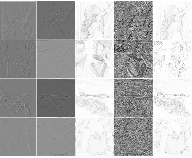
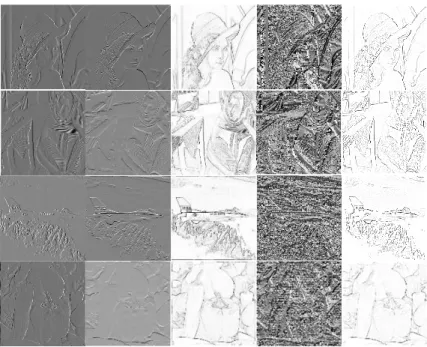
Figure 12 WTMM examples of 1st Level DWT for (a) Lena, (b) Barbara, (c) Airplane, and (d) Pepper images. From left to right: LH1 wavelet sub-band, HL1 wavelet sub-sub-band, WTMM magnitude (Mf), WTMM angle (Af), and WTMM coefficients. ... 60
Figure 13 WTMM examples of 2nd Level DWT for (a) Lena, (b) Barbara, (c) Airplane, and (d) Pepper images. From left to right: LH2 wavelet sub-band, HL2 wavelet sub-sub-band, WTMM magnitude (Mf), WTMM angle (Af), and WTMM coefficients. ... 61
Figure 14 WTMM examples of 3rd Level DWT for (a) Lena, (b) Barbara, (c)
sub-8 | P a g e
band, HL3 wavelet sub-band, WTMM magnitude (Mf), WTMM angle
(Af), and WTMM coefficients. ... 61
Figure 15 (a) WTMM of the original Lena image; (b) Lena watermarked image rotated by (15o); (c) Lena watermarked image scaled by (0.7); (d) Lena image watermarked translated by (80, 80). ... 62
Figure 16 (a) WTMM of the original Airplane image; (b) Airplane watermarked image rotated by (90o); (c) Airplane watermarked image scaled by (0.7); (d) Airplane watermarked image translated by (96, 96). ... 62
Figure 17 The overall proposed watermark embedding process... 64
Figure 18 The proposed 1-bit watermark embedding process. ... 66
Figure 19 The proposed multi-bit watermark embedding process. ... 67
Figure 20 The proposed watermark recovery process. ... 67
Figure 21 Stage 2 of the proposed watermark recovery scheme. ... 69
Figure 22 Stage 1.5 of the proposed watermark recovery process. ... 70
Figure 23 Normalized Cross-Correlation operation applied on the original watermark and the recovered watermark. ... 73
Figure 24 Cover images of resolution 512x512. ... 76
Figure 25 Cover images of resolution 256x256. ... 76
Figure 26 The ‘TEST’ logo image ... 77
Figure 27 The ‘ME’ logo image ... 77
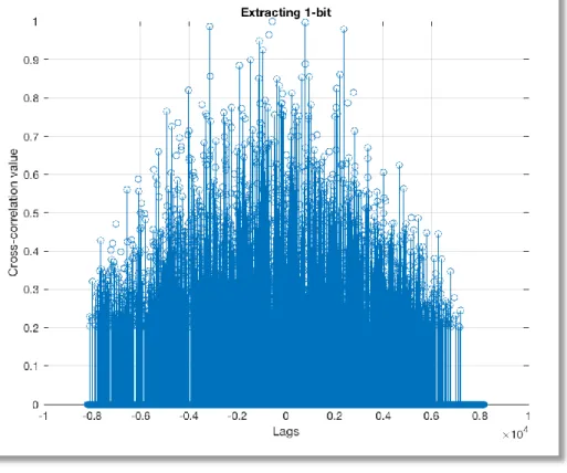
Figure 28 The detection of 1-bit watermark. ... 80
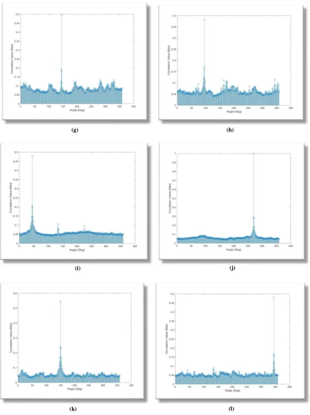
Figure 29 In case of an attack, the NCC profile shows many peaks. ... 81
Figure 30 Watermarked Lena images using the following wavelets: (a) Cardbal2; (b) GHM; (c) BAT02; (d) Daubechies (d4); and (e) Antonini 7.9. ... 83
Figure 31 Normalized Cross-correlation (NCC) results between the recovered and the original logos after a rotation attack for image Lena using: (a) Cardbal2; (b) GHM; (c) BAT02; (d) Daubechies (d4); and (e) Antonini 7.9. ... 84
Figure 32 Comparison of the results obtained using different types of wavelets/multiwavelets. The results are shown for 512x512 resolution images and the ‘TEST’ logo watermark. ... 85
9 | P a g e Figure 33 Comparison of the results obtained using different types of
wavelets/multiwavelets. The results are shown for 512x512 resolution images and the smaller ‘ME’ logo watermark. ... 86
Figure 34 Comparison of PSNR results for different types of
wavelets/multiwavelets. The results are shown for 512x512 resolution images and the ‘TEST’ logo watermark. ... 87
Figure 35 Comparison of PSNR results for different types of
wavelets/multiwavelets. The results are shown for 512x512 resolution images and the smaller ‘ME’ logo watermark. ... 87
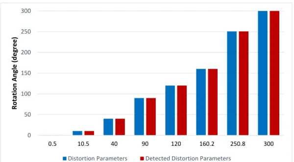
Figure 36 Original distortion parameters and the detected distortion parameters for rotation attacks. ... 91
Figure 37 Original distortion parameters and the detected distortion parameters for scaling attacks. ... 91
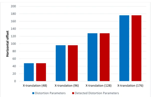
Figure 38 Original distortion parameters and the detected distortion parameters for translation attacks (horizontal shifts). ... 92
Figure 39 Original distortion parameters and the detected distortion parameters for translation attacks (vertical shifts). ... 92
Figure 40 Rotation attack examples for different images: Lena (15o), Airplane
(10o), Pepper (130o), Barbara (100o), Sailboat (90o), Parrots (170o),
Fruits (145o), Parrot (95o), Flower (45o), Natural (270o), Pepper3
(150o), Colors (345o). ... 95 Figure 41 Normalized Cross-Correlation peaks: (a) Lena (15o), (b) Airplane (10o),
(c) Pepper (130o), (d) Barbara (100o), (e) Sailboat (90o), (f) Parrots
(170o), (g) Fruits (145o), (h) Parrot (95o), (i) Flower (45o), (j) Natural
(270o), (k) Pepper3 (150o), (l) Colors (345o). ... 97 Figure 42 Restored watermarked images after undergoing a Rotation attack:
Lena (-15o), Airplane (-10o), Pepper (-130o), Barbara (-100o), Sailboat
(-90o), Parrots (-170o), Fruits (-145o), Parrot (-95o), Flower (-45o),
Natural (-270o), Pepper3 (-150o), Colors (-345o). ... 98 Figure 43 Normalized Cross-correlation (NCC) results between the recovered
and the original logos after a rotation attack: (a) Lena (15o), (b)
10 | P a g e
(90o), (f) Parrots (170o), (g) Fruits (14o), (h) Parrot (95o), (i) Flower
(45o), (j) Natural (270o), (k) Pepper3 (150o), (l) Colors (345o). ... 101 Figure 44 Watermarked images of size 256x256 after rotation attacks: Lena
(90o), Pepper2 (350o), Foods (10o). ... 102 Figure 45 Normalized Cross-Correlation peaks: (a) Lena (90o), (b) Pepper2
(350o), (c) Foods (10o). ... 102 Figure 46 Restored watermarked images after undoing the rotation attacks:
Lena (-90o), Pepper2 (-350o), Foods (-10o). ... 103 Figure 47 Normalized Cross-Correlation (NCC) results between the recovered
and the original logos after rotation attack: (a) Lena (90o), (b) Pepper2
(350o), (c) Foods (10o). ... 104 Figure 48 Watermarked images after scaling attacks: Lena (0.5), Fruits (0.5),
Flower (0.5), Pepper3 (0.6), Parrots (0.7), Parrot2 (0.7), Airplane (0.8), Natural (0.8), Colors (0.8), Barbara (0.9), Sailboat (0.85), Pepper (1.25). ... 105
Figure 49 Normalized Cross-Correlation peaks: (a) Lena (0.5), (b) Fruits (0.5), (c) Flower (0.5), (d) Pepper3 (0.6), (e) Parrots (0.7), (f) Parrot2 (0.7), (g) Airplane (0.8), (h) Natural (0.8), (i) Colors (0.8), (j) Barbara (0.9), (k) Sailboat (0.85), (l) Pepper (1.25). ... 108
Figure 50 Restored watermarked images after undoing the scaling attacks: Lena, Fruits, Flower, Pepper3, Parrots, Parrot2, Airplane, Natural, Colors, Barbara, Sailboat, Pepper. ... 109
Figure 51 (a) Lena (0.5), (b) Fruits (0.5), (c) Flower (0.5), (d) Pepper3 (0.6), (e) Parrots (0.7), (f) Parrot2 (0.7), (g) Airplane (0.8), (h) Natural (0.8), (i) Colors (0.8), (j) Barbara (0.9), (k) Sailboat (0.85), (l) Pepper (1.25). ... 112
Figure 52 Watermarked images of size 256x256 after scaling attacks: Pepper2 (0.6), Lena (0.85), Foods (1.35). ... 113
Figure 53 Normalized Cross-Correlation peaks: (a) Pepper2 (0.6), (b) Lena (0.85), (c) Foods (1.35). ... 113
Figure 54 Restored watermarked images after undergoing a scaling attack: Pepper2, Lena, Foods. ... 114
11 | P a g e Figure 55 The recovered ‘TEST’ logo watermark: (a) The original logo
watermark, and (b) the recovered logo watermark for the ‘Pepper2’ image after undergoing a scaling attack (Scaling: 0.6; NCC: 0.42). ... 114
Figure 56 Normalized Cross-Correlation (NCC) results between the recovered and the original logos after recovering the logo from a scaling attack for 256x265 images: (a) Pepper2 (0.6), (b) Lena (0.85), (c) Foods 1.35). ... 115
Figure 57 Watermarked images subjected to translation attacks: Lena (+80, -80), Airplane (+96, -96), Pepper (+64, -64), Barbara (+48, -48), Sailboat (+128, -128), Parrots (+80, -80), Fruits (+112, -112), Parrot2 (+40, 40), Flower (+160, 160), Natural (+160, 160), Pepper3 (+72, -72), Colors (+80, -80). ... 117
Figure 58 Detection of translation parameters through cross correlation: (a) Lena (+80, -80), (b) Airplane (+96, -96), (c) Pepper (+64, -64), (d) Barbara (+48, -48), (e) Sailboat (+128, -128), (f) Parrots (+80, -80), (g) Fruits (+112, -112), (h) Parrot2 (+40, -40), (i) Flower (+160, -160), (j) Natural (+160, -160), (k) Pepper3 (+72, -72), (l) Colors (+80, -80). ... 120
Figure 59 Restored watermarked images after undoing the translation attacks: Lena (-80, +80), Airplane (-96, +96), Pepper (-64, +64), Barbara (-48, +48), Sailboat (-128, +128), Parrots (-80, +80), Fruits (-112, +112), Parrot2 (-40, +40), Flower (-160, +160), Natural (-160, +160), Pepper3 (-72, +72), Colors (-80, +80). ... 121
Figure 60 Normalized Cross-Correlation (NCC) results between the recovered and the original logos after recovering the logo from a translation attack: (a) Lena (-80, +80), (b) Airplane (-96, +96), (c) Pepper (-64, +64), (d) Barbara 48, +48), (e) Sailboat 128, +128), (f) Parrots 80, +80), (g) Fruits 112, +112), (h) Parrot2 40, +40), (i) Flower (-160, +160), (j) Natural (-(-160, +160), (k) Pepper3 (-72, +72), (l) Colors (-80, +80). ... 124
Figure 61 The recovered ‘TEST’ logo watermark: (a) The original logo
watermark, and (b) the recovered logo watermark for the ‘Flower’ image after undergoing a translation attack (Translation: 160, 160; NCC: 0.97). ... 124
12 | P a g e Figure 62 Watermarked images of size 256x256 subjected to translation
attacks: Lena (+40, -40), Pepper2 (+32, -32), Foods (+60, -60). ... 125
Figure 63 Detection of translation parameters through cross-correlation: (a) Lena (+40, -40), (b) Pepper2 (+32, -32), (c) Foods (+60, -60). The exact translation attack parameters are found by subtracting the height and width of the WTMM image from the values ‘X’ and ‘Y’ respectively. ... 125
Figure 64 Restored watermarked images of size 256x256 after undoing the translation attacks: Lena (-40, +40), Pepper2 (-32 +32), Foods (-60, +60). ... 126
Figure 65 Normalized Cross-Correlation (NCC) results between the recovered and the original logos after recovering the logo from a translation attack: (a) Lena (-40, +40), (b) Pepper2 (-32, +32), (c) Foods (-60, +60). ... 127
Figure 66 The recovered ‘TEST’ logo watermarks for the Antonini 7.9 wavelet:
(a) The original logo watermark (b) Airplane (Scaling: 0.2; NCC: 0.55), (c) Barbara (Rotated: 150o; NCC: 0.98). ... 130 Figure 67 The recovered ‘TEST’ logo watermarks for the Daubechies (d4)
wavelet: (a) The original logo watermark (b) Pepper (Scaling: 0.2; NCC: 0.43), (c) Barbara (Rotated: 15o; NCC: 0.0.97). ... 130 Figure 68 Comparison of the results obtained using different types of
wavelet/multiwavelet filters. The results are obtained using the ‘TEST’ logo watermark and represent the averages figure of the four images used for this comparison. ... 133
Figure 69 Comparison of the results obtained using different types of wavelet/multiwavelet filters. The results are obtained using the ‘TEST’ logo watermark and represent the averages figure of the four images used for this comparison. ... 133
Figure 70 Comparison of the results obtained using different types of wavelet/multiwavelet filters. The results are obtained using the ‘TEST’ logo watermark and represent the averages figure of the four images used for this comparison. ... 134
13 | P a g e Figure 71 Robustness against rotation attacks of the proposed method
compared to [55], for the ‘Lena’ image. ... 135
Figure 72 Robustness against rotation attacks of the proposed method compared to [55], for the ‘Pepper’ image. ... 136
Figure 73 Robustness against scaling attacks of the proposed method compared to [55], for the ‘Lena’ image. ... 137
Figure 74 Robustness against scaling attacks of the proposed method compared to [55], for the ‘Pepper’ image. ... 137
Figure 75 Robustness translation scaling attacks of the proposed method compared to [55], for the ‘Lena’ image. ... 138
Figure 76 Robustness against translation attacks of the proposed method compared to [55], for the ‘Pepper’ image. ... 139
Figure 77 Robustness against rotation attacks of the proposed method compared to [77], for the ‘Lena’ image. ... 140
Figure 78 Robustness against scaling attacks of the proposed method compared to [77], for the ‘Lena’ image. ... 140
Figure 79 Robustness against translation attacks of the proposed method compared to [77], for the ‘Lena’ image. ... 141
Figure 80 The recovered ‘TEST’ logo watermarks: (a) The original logo
watermark (b) Lena (Rotation: 40o; NCC: 0.98), (c) Barbara
(Translation: 144, 144; NCC: 0.97) (d) Lena (Scaling: 0.4; NCC: 0.66), (e) Pepper3 (Scaling: 0.4; NCC: 0.75)... 145
Figure 81 The recovered ‘ME’ logo watermarks: (a) The original logo watermark
(b) Sailboat (Rotation: 140o; NCC: 0.98), (c) Sailboat (Scaling: 0.4;
NCC: 0.81). ... 146
Figure 82 The recovered ‘TEST’ logo watermarks in case of 256x256 size cover
images: (a) The original logo watermark (b) Lena (Scaling: 0.7; NCC: 0.56), (c) Pepper2 (Scaling: 0.7; NCC: 0.66), (d) Foods (Scaling: 0.7; NCC: 0.43) and (e) Foods (Rotation: 110o; NCC: 0.99). ... 146 Figure 83 The recovered ‘ME’ logo watermarks for 256x256 resolution images:
(a) The original logo watermark (b) Lena (Scaling: 0.5; NCC: 0.29), (c) Foods (Scaling: 0.8; NCC: 0.98). ... 147
14 | P a g e
List of Acronyms
ABC Artificial Bee Colony
AC Alternating Current
AEAD Average Edges Angles Difference
AT Arnold Transform
AWGN Additive While Gaussian Noise
BER Bit Error Rate
BPP Bits Per Pixel
CAGR Compound Annual Growth Rate
CQ Correlation Quality
CSF Contrast Sensitivity Function dB Decibel
DCT Discrete Cosine Transform DFT Discrete Fourier Transform
DMWT Discrete Multi-Wavelet Transform DWT Discrete Wavelet Transform ESDR Edges Standard Deviation Ratio
FFT Fast Fourier Transform
FMT Fourier-Mellin Transform
FNR False Negative Rate
FPR False Positive Rate
GA Genetic Algorithms
HH High-High Sub-Band HL High-Low Sub-Band HVS Human Visual System
15 | P a g e
IDWT Inverse Discrete Wavelet Transform JPEG Joint Photographic Experts Group LH Low-High Sub-Band
LL Low-Low Sub-Band LSB Least-Significant-Bit
MLM Maxima Location Mean
MOS Mean Opinion Score
MPEG Motion Picture Experts Group
MRA Multi-Resolution Analysis
MSE Mean Square Error
NCC Normalized Cross-Correlation NSST Non-Subsampled Shearlet Transform
PHT Polar Harmonic Transform
PRN Pseudo-Random Number PSNR Peak Signal to Noise Ratio
QR Quick Response Code
RGB Red, Green, Blue ROI Region of Interest
RST Rotation, Scaling, Translation SIFT Scale Invariant Feature Transform
SNR Signal-to-Noise Ratio
SSIM Structural Similarity Index SVD Singular Value Decomposition
WNR Watermark-to-Noise Ratio
16 | P a g e
CHAPTER 1: INTRODUCTION
1.1 Background
Nowadays, digital multimedia content (and in particular, image data) is widely available and is frequently distributed over the Internet. Copyright protection of such content is important to ensure its rightful ownership and legal distribution. Thus, storing the ownership information within the digital data itself has emerged as an active area of research.
Digital Watermarking is a valuable tool which enables the hiding or embedding of a signal (usually containing ownership information) into another signal (usually image or video content). It can be used to protect digital data against copyright infringement [1]. Important applications of watermarking include broadcast monitoring, owner identification, proof of ownership, authentication, fingerprinting, copy control and covert communications [2]. In particular, watermarking can be successfully used in the following areas:
• Broadcasting: where broadcasters can use watermarking to track and
verify TV programs and advertisements,
• Entertainment: where movie studios can detect and deter piracy of
movies. Similarly, watermarks can also be used to secure the distribution of digital cinema content,
• Banking: where central banks can use watermarks to prevent digital
counterfeiting of currency notes,
• Photography: where photographers can identify and manage the copyright
of their photographs, and can embed additional metadata,
• Government Organizations: where watermarking can be used to
authenticate employee IDs, to prevent theft, fraud and counterfeiting of important documents.
The global digital watermarking market has seen a continuous growth over the past few years and the growth is expected to also continue in future. For example, in 2015, the
17 | P a g e
global watermarking market was worth USD 1.0663 Billion while by 2020, it is forecasted to grow by approximately 300% i.e. to around USD 2.8989 Billion [3].
This translates to a compound annual growth rate (CAGR) of 22.1% from 2015 to 2020. The healthy and sustained growth of digital watermarking market shows a continued interest of stakeholders in watermarking technology.
An important problem related to watermarking is that it is not sufficient just to store the ownership information, but also to hide it and separate it from the real data and to protect it against tampering. It is to be noted that watermarking is very much different from encryption. While, they both provide protection of the data, encryption only provides protection during transmission. The data is not protected once it is decrypted. On the other hand, a watermark is always present in the data [4].
A watermark exhibits several characteristics. Among others, these include: robustness and tamper resistance, transparency, capacity, fidelity, computational cost, and false positive rate [2]. Robustness is the characteristic of a watermark that indicates how well the watermark can survive common signal processing operations such as lossy compression. Tamper resistance can be further classified into four types: resistance against active, passive, collusion or forgery attacks. The various types of attacks are discussed further in Chapter 2. Fidelity refers to the ability of a watermark to embed into another signal without visibly changing that signal. Computational cost usually determines the computational resources, speed, or time required to embed the watermark or to recover and determine the authenticity of the watermark. Lastly, the false positive rate is the rate at which the watermark is detected in a signal even when the signal does not contain the watermark. An ideal watermark should be robust, tamper resistant, have high fidelity, small computational cost and a zero false positive rate. However, due to the various constraints in the real world, this is not always possible and usually compromise is made on one or more of these characteristics when watermarking is used in real world applications. To address the above issues, different methods have been proposed in the literature. These methods can be broadly classified into two categories: spatial domain methods and transform domain methods.
18 | P a g e
Spatial domain methods are easy to implement but are typically less robust against attacks. On the other hand, transform domain methods are more complex compared to the spatial domain methods, but they are relatively more robust [1]. A detailed discussion of these methods is presented in Chapter 2.
1.2 Scope
The main goal of robust logo watermarking and of this research is to protect intellectual property of copyrighted materials distributed by third parties, by hiding a perceptually invisible logo in the host content. The watermarking technique should be robust to intentional and unintentional attacks such as image compression, image manipulation, noise addition, loss during transmission, etc. The aim is to maximize the capacity and robustness of the watermark while at the same time preserving its invisibility.
The watermarking technique should be designed in such a way that third parties cannot change or remove the watermark. The watermark should be very difficult to remove without destroying the watermarked host image in the process.
A literature survey is carried out to establish previous relevant research into robust (logo) watermarking algorithms. Various algorithms and techniques are investigated in order to achieve the above requirements and improve on the existing techniques.
1.3 Aims and Objectives
The main aim of this work is to propose a novel blind logo watermarking technique for RGB images, which is robust to geometrical transforms. This aim is achieved with the help of the following objectives:
a. Investigate spread spectrum based techniques for robust (logo) image watermarking.
b. Investigate the effect of spatial and transform domain methods for robust (logo) image watermarking.
c. Investigate the use of Discrete Wavelet Transforms (DWT) and Discrete Multi-Wavelet Transforms (DMWT) for (logo) image watermarking of colour (RGB) images.
19 | P a g e
d. Investigate the use of Wavelet Transform Modulus Maxima (WTMM) to achieve robustness against geometrical attacks, and in particular robustness against RST attacks.
e. Investigate robustness to different types of attacks and evaluate the performance of the proposed technique.
1.4 Thesis Outline
The remaining part of the thesis includes six chapters.
In Chapter 2, fundamental concepts of watermarking are presented. These include the components of a watermarking model, classification of watermarking schemes, properties of a watermark, applications of watermarking, types of attacks, and classification of watermarking techniques. In Chapter 3, a literature survey of the different robust watermarking methods is presented. These include both spatial and transform domain techniques. Moreover, frequently used spread spectrum techniques have also been reviewed and the differences between the existing spread spectrum techniques and the proposed technique have been highlighted. Wavelet transform modulus maxima and related concepts are introduced in Chapter 4. This is followed by a description of the proposed novel watermarking scheme in Chapter 5. A discussion of the experimental results of the proposed method are presented in Chapter 6. Finally, conclusions drawn from this work are presented in Chapter 7.
20 | P a g e
CHAPTER 2: FUNDAMENTALS
There are several ways to perform watermarking of multimedia content. Usually multi-bit information is invisibly embedded, in host content such a song, text, a movie or a picture. Watermarking can be carried out in the spatial domain as well as in the transform domain, and various transforms have been proposed and used over time. The watermark should be imperceptible, in order to preserve the quality of the watermarked content, and various human visual models have been proposed to address this. Robustness and imperceptibility are the key concerns when watermarking quality is judged. Depending on the application, watermarking capacity is also a key factor. A general solution for increasing robustness is to embed the watermark with higher power. However, this impacts on invisibility, so any watermarking scheme needs to achieve a trade-off between robustness, capacity and the invisibility of the watermark. Various techniques have been proposed to achieve this (e.g., [4], [5], [6], and [7]). Generally, spread-spectrum modulation based techniques (e.g., [8], [9]) are frequently used due to their inherent noise-like nature and their ability to securely spread the watermark in the entire image content. Another frequently used technique is quantization watermarking [10], [11], and [12].
2.1 Components of a Basic Watermarking Model
The fundamental components of a digital watermarking process include [13]:
- Watermark generation: It refers to the process of generating a suitable watermark for an application. Watermark generation and the very size and type of the watermark are usually constrained by the properties required in a given application. For example, in a copyright protection application, a watermark may need to be able to withstand common signal and image processing operations. Hence, the watermark’s robustness needs to be considered while selecting a watermark which would be suitable for such applications.
21 | P a g e
- Watermark embedding: It refers to the process of finding a suitable method and location for the embedding or insertion of the watermark in the host multimedia content (e.g., a digital image).
- Watermark detection: It refers to the process of detecting the watermark that has been embedded in the host multimedia content. This will allow one to establish the authenticity and/or the ownership of the content.
2.2 Classification of Watermarking Schemes
Watermarkingschemes can be classified in many ways. Some of these are as follows: - Symmetric vs Asymmetric Watermarking:
Symmetric watermarking schemes use the same key for the embedding and the detection of the watermark. A requirement of these schemes is that they require the key that is used for watermark embedding to be available at the watermark detector. This can potentially lead to a security problem such as the removal of the watermark. On the other hand, Asymmetric watermarking schemes use different keys for the embedding and the detection of the watermark. In these schemes, a private key is used for embedding the watermark while the detector is only aware of a public key. This arrangement makes it impossible or extremely difficult to rely on compromising a key in order to remove the watermark.
- Robust, Semi-fragile, and Fragile Watermarking:
Watermarks can be classified into three categories based on their robustness property. These are: robust, semi-fragile, and fragile [17]. Robust watermarks are designed to be resilient to attacks and very difficult to remove. On the other hand, semi-fragile watermarks are capable of partially tolerating changes to the watermarked image (e.g., the addition of quantization noise from lossy compression). Lastly, fragile watermarks are meant to be easily destroyed if the watermarked image is manipulated even slightly.
- Spatial Domain vs Transform Domain:
Spatial domain methods are simple techniques that involve direct modification of pixel intensities. They commonly involve additive watermarking techniques as
22 | P a g e
well as Least Significant Bit (LSB) modification techniques in which the least significant bit of each bit-plane is modified [20]. The main advantages of spatial domain watermarking techniques lie in their simpler implementation and lower computational time complexities while the main drawback of these techniques is that they tend to offer lower watermark capacity and be less robust to attacks [21]. On the other hand, transform domain techniques insert information into transform coefficients. These methods are discussed in detail in Section 2.6.
2.3 Watermarking Properties
- Perceptual similarity (Imperceptibility): Achieving visual imperceptibility means that even though the content of an image will change as a result of embedding the watermark, visually, the difference is unnoticeable.
Several metrics can be employed to evaluate the perceptual similarity. These can be broadly classified into methods based on objective and subjective criteria. While methods based on objective criteria use mathematical formula to quantify the perceptual similarity, subjective methods mainly rely on the opinion of the users. Correlation quality (CQ), peak signal to noise ratio (PSNR), mean square error (MSE) and structural similarity index (SSIM) are some of the examples of objective methods while Mean Opinion Score (MOS) is one of the most commonly used subjective methods for the evaluation of image quality/similarity. - Visibility: A visible watermarking scheme is a scheme that allows the watermark
to be visible on the object in which it is embedded. Its use can be in displaying a company logo, etc.
Hence, watermarking schemes can be classified as either ‘visible’ or ‘invisible’ based on the appearance of the watermark on the image.
It is important to differentiate between ‘perceptual similarity’ and ‘visibility’. They can be easily confused with each other because of their similarities.
However, while ‘perceptual similarity’ aims to reduce the perceptual difference between images before and after watermarking, ‘visibility’ aims to make the watermark appear on the image with a strength that can normally be controlled. Thus ‘visibility’ results in a perceptual difference between images before and
23 | P a g e
after watermarking. By in large, the main focus of research has been on invisible watermarking schemes.
- Blind embedding/retrieval: Blind embedding/retrieval is a property that defines the computational independence on the original information or its derivatives to retrieve the required watermark information. A watermarking scheme can be categorized as a blind, semi-blind, or non-blind.
A blind watermarking scheme requires no original input image or any information derived from it in order to recover the embedded watermark. On the other hand, a semi-blind watermarking scheme often refers to the schemes that can operate objectively without the original image and its derived information, but still require the original image. Lastly, non-blind watermarking schemes require the original image in order to be able to recover the watermark [13].
- Invertibility: Invertibility is the property that defines whether a watermarked image can be restored to its original version without leaving any embedding distortion behind.
- Robustness: Robustness has been defined differently by different authors. For example, according to Piper and Safavi-Naini [14], a robust watermarking scheme is the one that can detect watermark in a ‘processed’ image. On the other hand, Cox et al. [15] define it as the ability to detect the watermark after common signal processing operations. Hence, keeping in view both these definitions, robustness can be defined as the degree to which a watermarking scheme can resist modifications to the watermarked image.
These modifications can be either intentional in the form of attacks designed to render the watermark undetectable, or unintentional, such as the side effect of performing various common signal processing operations such as compression. - Embedding capacity: It refers to the amount of watermarking data that can be
(robustly) embedded without compromising on the perceptual similarity of the watermarked and the non-watermarked image.
Capacity estimation of watermarking is an active area of research. It is usually expressed in terms of the number of bits or the number of bits per pixel (bpp).
24 | P a g e
- Error probability: Error probability defines the reliability of a watermarking scheme. Commonly used metrics for determining the error probability of a watermarking scheme are bit error rate (BER), false positive rate (FPR), and false negative rate (FNR). BER may be improved by using suitable error correction codes to protect the watermark.
o Bit error rate: It is defined as the number of bits in error divided by the total number of bits.
o False positive rate: It can be defined as the rate at which an algorithm falsely detects a watermark though in reality the watermark is not present.
o False negative rate: It can be defined as the rate at which an algorithm fails to detect the watermark even though the watermark is present.
A zero FPR and FNR represents an ideal or very reliable detection. However, this may not be achievable in practice due to attacks. Hence, the aim in watermarking applications is usually to achieve a low FPR and FNR as well as achieving a very low BER (e.g., of the order of 10-6).
- Normalized Cross-correlation coefficient: The normalized cross-correlation (NCC) coefficient of two images is a measure of similarity between the two images. It is generally used to evaluate the quality of a recovered watermark. The NCC 𝛾 (𝑢, 𝑣) of an image ‘𝑓’ with coordinates ‘𝑥’ and ‘𝑦’ and its template ‘𝑡’ with its coordinates ‘𝑢’ and ‘𝑣’ can be computed as in Eq. (1) [16].
𝜸(𝒖, 𝒗, ) = ∑𝒙,𝒚[𝒇(𝒙,𝒚)−𝒇̅𝒖,𝒗][𝒕(𝒙−𝒖,𝒚−𝒗)−𝒕̅] {∑ [𝒇(𝒙,𝒚)−𝒇̅𝒖,𝒗] 𝟐 ∑ [𝒕(𝒙−𝒖,𝒚−𝒖)−𝒕̅]𝟐 𝒙,𝒚 𝒙,𝒚 } 𝟎.𝟓 (1)
In Eq. (1), 𝑡̅ is the mean of the template and 𝑓̅𝑢,𝑣 is the mean of 𝑓 (𝑥, 𝑦) in the region
under the template.
Among these properties, imperceptibility, robustness, and capacity are generally the more important properties of a watermarking scheme. Ideally, a watermark should achieve all
25 | P a g e
three properties at the same time, but practically, this is often not possible. A trade-off has to be made among these constraints as they are generally conflicting requirements. The trade-off is generally made on the basis of the requirements of each specific watermarking application. A possible trade-off is shown in Figure 1.
Figure 1 Possible trade-off between constraints
Generally, among the above properties, imperceptibility is of very high importance. That is because the artefacts produced during the process of watermark embedding are both annoying and undesirable.
Moreover, they may also compromise the commercial value of the image. Robustness is another important property of a watermark. Unfortunately, increasing robustness often implies some perceptual degradation. On the other hand, improving imperceptibility imposes limitations on robustness. Similarly, increasing capacity (i.e. the ability to hide a larger amount of information) limits the robustness of the watermark while increasing robustness limits the capacity of the watermark. As a result, imperceptibility, robustness and capacity are opposing constraints which cannot be all achieved at the same time. Hence, usually, a trade-off is made based on the importance of each of these factors with respect to the target application.
26 | P a g e
2.4 Applications of Watermarking Techniques
Watermarking can be useful in a number of applications. Each target application has its own set of constraints and requirements. It is not possible to address all watermarking properties for every algorithm. Rather, it is more sensible to identify a target application first, identify its constraints, and then design a practical watermarking scheme which works under those constraints.
Watermarking applications can be classified into five broad categories [18]: protection of intellectual property rights, content verification, information hiding, and annotation. A brief description of each application category is presented below:
- Protection of Intellectual Property Rights: The purpose of watermarking schemes aimed at this class of applications is to convey information about content ownership and intellectual property rights.
Application scenarios in this class include copyright protection, copy protection and fingerprinting, and rely on robust watermarks.
- Content Verification: The purpose of watermarking schemes aimed at this class of applications is to ensure that the original multimedia content has not been altered by a third party. Moreover, they can also aim to determine the type and location of alteration. Application scenarios in this class include authentication and integrity checking. Such applications rely on fragile watermarks.
- Information Hiding: The purpose of the embedded watermark in a watermarking scheme aimed at this class of applications is to offer a side channel used to carry additional information. Application scenarios include, system enhancement and secret communications.
- Annotation: The purpose of watermarking schemes aimed at this class of applications is to convey the object-specific information to users of the media. For example, augmented contents, multimedia indexing, content based retrieval, patient record identification for medical images, etc.
- Broadcast Monitoring: Advertisers are generally interested in making sure that they receive the airtime that they have paid for. Similarly, artists and musicians
27 | P a g e
are also interested in making sure that they receive royalty amounts corresponding to the actual air time. Watermarks can be used for broadcast monitoring by embedding a watermark in each advertisement or other media content. Monitoring stations can then be used to receive the broadcast content and identify the time and location of the broadcast of the relevant content [19].
2.5 Watermarking Attacks
Any malicious attempt to perform unauthorized embedding, removal, or detection of a watermark can be termed as a watermarking attack [13]. Watermarking attacks are often dictated by the capabilities and the needs of the adversary.
Attacks on watermarking can be broadly classified into two types: active and passive.
2.5.1 Active attacks
An active attack involves unauthorized embedding and/or unauthorized removal of the watermark. These attacks usually attempt to alter the watermarked image in one way or another.
Active attacks can be categorized in the following types:
- Elimination: In an elimination attack, an adversary tries to generate an output image, which is perceptually similar to the watermarked image but for which the watermark is no longer detected. These methods aim to completely remove the watermark from the watermarked image.
- Collusion: In a collusion attack, an adversary has access to multiple copies of the same host data each watermarked with a different watermark. This information can be used to compromise the embedded watermarks by averaging all copies together to obtain a close approximation of the original image.
- Masking: Masking attacks do not actually remove the watermark but make it undetectable to the detectors.
- Distortion: The attacks aim to distort the watermark to make it undetectable. De-noising and desynchronization attacks are two subclasses of distortion attacks. Rotation, scaling, and translation (RST) and affine transforms are common geometric attacks that can be used to distort watermarks.
28 | P a g e
- Forgery: In a forgery attack, an adversary or unauthorized person attempts to embed a valid watermark of their own in an attempt to claim false ownership of the watermarked multimedia content.
- Copy: This attack is similar to a forgery attack but in this case the attacker copies a watermark from one valid watermarked image to another in order to falsely authenticate an invalid watermarked image.
- Ambiguity: An ambiguity attack is aimed at making the detection process ambiguous and thus allowing even an invalid watermark to pass as a valid one. - Scrambling: These attacks aim to scramble the samples of the watermark before
passing it through a detector, in order to avoid detection. The samples of the watermark are later on descrambled before using the host content. A typical example of a scrambling attack is the mosaic attack.
2.5.2 Passive attacks
A passive attack involves unauthorized detection of the watermark. These attacks are aimed at knowing the presence or absence of the watermark.
- Detection only: In these attacks, an attacker only detects the presence of a valid watermark in a watermarked image.
- Incision detection: In these attacks, apart from detection of the watermark in a watermarked image, the attacker can distinguish the watermark from that of other watermarked images.
- Comprehensive detection: In these attacks, the attacker not only knows the presence of the watermark and can distinguish it from other watermarked images, but also obtains information, at least partially, about the content carried by the watermark, without modifying the watermarked image.
29 | P a g e
2.6 Transform Domain Watermarking Schemes
As discussed in Section 2.2, transform domain techniques insert information into transform coefficients. Many types of transforms have been used for this purpose such as: Fourier transforms [22] and fractional Fourier transforms [23], Cosine transforms [24], Wavelet transforms [25], fractional Wavelet transforms [26], fractional dual tree complex Wavelet transforms, Hadamard transforms, Curvelet transforms, and Singular Value Decomposition (SVD) transforms [27]. Amongst these, Cosine transforms and Wavelet transforms tend to be more frequently used. Generally, transform domain techniques provide higher imperceptibility and robustness to attacks but are more complex to implement and have higher computational complexity. Some of these transforms benefit from established Human Visual System (HVS) models that can be very useful in a watermarking scheme.
2.6.1 Discrete Cosine Transform
The Discrete Cosine Transform (DCT) transforms an image from spatial or pixel domain to frequency domain. It is an important transform mainly because of its energy compaction property which allows it to store most of the information in very few (low-frequency) coefficients. Because of its good energy compaction performance, it has been adopted in image compression standards such as Joint Photographic Experts Group (JPEG) as well as in many Motion Picture Experts Group (MPEG) video compression standards.
Forward DCT is used to transform the image into DCT coefficients, while inverse DCT is used to reconstruct the image back from the transform coefficients. Mathematically, the DCT is defined as:
𝐷(𝑖, 𝑗) = 1 √2𝑁𝐶(𝑖)𝐶(𝑗) ∑ ∑ 𝑝(𝑥, 𝑦) cos [ (2𝑥+1)𝑖𝜋 2𝑁 ] cos [ (2𝑦+1)𝑗𝜋 2𝑁 ] 𝑁−1 𝑦=0 𝑁−1 𝑥=0 (2) where 𝐶(𝑢) = { 1 √2 𝑖𝑓 𝑢 = 0 1 𝑖𝑓 𝑢 > 0 (3)
30 | P a g e
Here 𝑝 (𝑥, 𝑦) is the pixel at position (𝑥, 𝑦) of the image. 𝑁 is the size of the block on which the DCT is applied.
Commonly, the DCT is applied on small 8x8 size blocks, as shown in Figure 2. Here,
𝑁 = 8, so Equation (1) reduces to: 𝐷(𝑖, 𝑗) =1 4𝐶(𝑖)𝐶(𝑗) ∑ ∑ 𝑝(𝑥, 𝑦) cos [ (2𝑥+1)𝑖𝜋 16 ] cos [ (2𝑦+1)𝑗𝜋 16 ] 7 𝑦=0 7 𝑥=0 (4)
Similarly, the inverse DCT can be obtained using the following relationship: 𝑝(𝑖, 𝑗) = 1 4[∑ ∑ 𝐶(𝑖)𝐶(𝑗)𝐷(𝑖, 𝑗) cos [ (2𝑥+1)𝑖𝜋 16 ] cos [ (2𝑦+1)𝑗𝜋 16 ] 7 𝑦=0 7 𝑥=0 ] (5)
It can be seen from Figure 2 that after applying DCT, the Low Frequency (LF) content is represented by transform coefficients in the top-left corner of the DCT matrix, the High Frequency (HF) content is represented by transform coefficients in the bottom-right corner of the DCT matrix while the Medium Frequency (MF) content is represented by the remaining transform coefficients.
It is also important to note that due to the block based structure of DCT, blocking artefacts are commonly associated with it. However, in the context of watermarking, DCT is associated with good perceptual invisibility and acceptable robustness against JPEG compression [20].
31 | P a g e
2.6.2 Discrete Wavelet Transform
The Discrete Wavelet Transform (DWT) is another important tool for signal analysis. It shares some similarities with the Discrete Fourier Transform (DFT). For example, both DWT and DFT represent a signal through a linear combination of their basis functions. But, for DFT, the basis functions are dilations of sinusoidal signals (sines and cosines, or just cosines for the DCT transforms) with each of the sinusoids spanning the entire time interval. On the other hand, for the DWT, the basis functions are different translations and dilations of a ‘Mother’ wavelet along with a scaling function. Unlike DFT, for DWT, each basis function spans a reduced sub-interval. Both DFT and DWT provide frequency localization through the dilations of their basis functions. Hence, both DFT and DWT can be used to analyse frequency information about a signal. However, the basis functions of DFT are not finite and hence the DFT does not provide time localization. On the other hand, the basis functions of DWT are compact and finite and as such the DWT can provide time localization (or localization in space for the 2D case) as well. Hence, the DWT can be used to obtain both time (or space) and frequency information about a signal while DFT is limited to only providing frequency information about a signal. In DWT, a signal is decomposed into a set of basis functions called ‘wavelets’. These wavelets can be obtained from the ‘mother wavelet’ using techniques known as dilation and shifting. Mathematically, this process can be represented using the following relationship:
𝜓𝑎,𝑏(𝑡) = 1 √𝑎𝜓(
𝑡−𝑏
𝑎 ) (6)
Here 𝑎 is the dilation (scaling) parameter and 𝑏 is the shifting parameter.
Theoretically, the number of types of mother wavelets can be infinite [28] but in practice the number of mother wavelets is relatively limited. It is important that the selected type and order of the filter closely matches the characteristics of the target signal. The order of a wavelet determines the smoothness and compactness of the wavelet. For example, the higher order wavelets are smoother but less compact in time. Generally, the dominant
32 | P a g e
features of the signal under analysis determine the type and order of the filter to be used for analysis. Some of the commonly used wavelets are as follows:
- Haar: It is one of the simplest types of wavelets. It is discontinuous and appears similar to a step function. It is the only orthogonal wavelet with a linear phase. - Daubechies: The Daubechies wavelet family is named after its inventer, Ingrid
Daubechies. It comprises a family of wavelets. Each wavelet in the family is represented using the notation dbN where ‘N’ represents the order of the wavelet. It is to be noted that the db1 wavelet is the same as the Haar wavelet.
- Biorthogonal: Biorthogonal wavelets have linear phase. Generally, these wavelets feature a pair of scaling functions and filters. One of the scaling functions in the pair is used for analysis and the other for synthesis. Different Biorthogonal wavelets are used for wavelet decomposition and reconstruction. - Coiflets: Coiflets were, introduced by Daubechies at the request of R. Coifman.
The Coiflet wavelet and scaling functions, have 2𝑁 and respectively 2𝑁 − 1
moments equal to zero.
- Symlets: These wavelets are very similar to the Daubechies wavelets and were indeed introduced as a modification of the Daubechies wavelets by Daubechies herself. Hence, both the Daubechies and Symlets wavelet families have very similar properties. Symlets are known for their nearly symmetrical functions. - Mexican Hat: The Mexican Hat wavelet (or the Ricker wavelet) is derived from
a function which is proportional to the second derivative of the Gaussian Probability Density Function (PDF). It does not have any scaling function.
- Morlet: Like the Mexican Hat wavelet, a Morlet wavelet also does not have a scaling function. But unlike the Mexican Hat wavelet, which is implicit, the Morlet wavelet is explicit.
- Meyer: Both the scaling and wavelet functions associated with the Meyer wavelet are represented in the frequency domain.
33 | P a g e
Figure 3 shows examples of the different types of wavelets.
Figure 3 Different types of wavelets: (a) Haar, (b) Daubechies, db2, (c, d) Biorthogonal 1.3 pair, (e) Coiflet, coif2, (f)
Symlet, sym2, (g) Mexigan hat, (h) Morlet, (i) Meyer scaling function, and (j) Meyer wavelet function. From the point of view of signal processing, a wavelet is similar to a bandpass filter [29]. In particular, a wavelet transform can be considered as filtering using a set of octave band filters. When higher octave bands are added, more detail or resolution is added to the signal. Mallat [30], [31], and Meyer [32] introduced the concept of Multi-Resolution Analysis (MRA). They used MRA for constructing orthonormal bases of wavelets. 2.6.2.1 Implementation of Wavelet Transform using Filter Banks
The DWT is commonly implemented using filter banks. For example, a signal x[n] is simultaneously passed through a high pass filter with an impulse response h[n] and a low pass filter with an impulse response g[n]. The output of both the filters is subsampled by
(a) (b) (c) (d)
(e) (f) (g) (h)
34 | P a g e
a factor of 2. The output of the low pass filter g[n] after subsampling are called the approximation coefficients. On the other hand, the output of the high pass filter h[n] after subsampling, are called the detail coefficients (See Figure 4).
Figure 4 Block diagram of one level of discrete wavelet transform.
In order to further increase the frequency resolution, the sub-sampled output of the low pass filter is again passed through low and high pass filters. The new outputs are again sub-sampled i.e., 𝑦𝑙𝑜𝑤[𝑛] = ∑ 𝑥[𝑘]𝑔[2𝑛 − 𝑘] ∞ 𝑘=−∞ 𝑦ℎ𝑖𝑔ℎ[𝑛] = ∑ 𝑥[𝑘]ℎ[2𝑛 − 𝑘] ∞ 𝑘=−∞ Or more precisely, 𝑦𝑙𝑜𝑤 = (𝑥 ∗ 𝑔) ↓ 2 𝑦ℎ𝑖𝑔ℎ = (𝑥 ∗ ℎ) ↓ 2
where 𝑦𝑙𝑜𝑤 and 𝑦ℎ𝑖𝑔ℎare the outputs of the low pass and high pass filters respectively and
↓ represents a subsampling operation. This process can be represented with the help of a binary tree also known as a filter bank.
The process can be repeated several times, each time resulting in an increased frequency resolution. An example of a three-level filter bank is shown in Figure 5.
Detail coefficients Approximation coefficients
35 | P a g e
Figure 5 Example of a three-level filter bank.
At each level of the three-level filter bank shown in Figure 5, the signal is decomposed into low and high frequencies. The decomposition process requires the input signal to be a multiple of 2n (n being the number of levels). An example of the frequency domain representation of the DWT is shown in Figure 6. Here, 𝑓𝑛 represents the maximum frequency.
Figure 6Frequency domain representation of 3-level DWT decomposition.
2.6.2.2 2D-Discrete Wavelet Transform
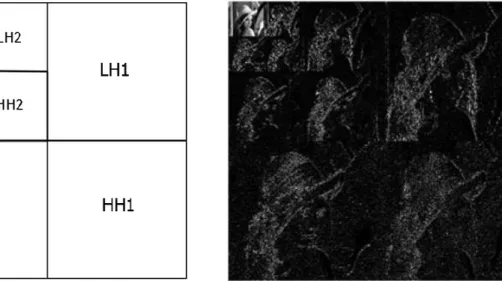
Since digital images are 2D signals, a two-dimensional DWT (2D-DWT) is required to analyse them. When a 2D-DWT is applied on an image, it splits the image into sub-bands of different frequencies as shown in Figure 7, where HH, HL, LH, and LL denote the High-High, High-Low, Low-High, and Low-Low sub-bands of the image, while the number following each pair denotes the decomposition level. At each level, the LL sub-band corresponds to (low frequency) approximation coefficients while the HL, LH, and
36 | P a g e
HH sub-bands correspond to (high frequency) detailed coefficients in vertical, horizontal, and diagonal directions respectively.
Figure 7 Level 3 image decomposition using 2-D wavelet transform: (a) sub-band representation and (b)
decomposition of Lena test image.
It is to be noted that the wavelet transform uses less coefficients to analyse low frequency content which has little variation (and as such there is no need to use too many coefficients to accurately describe it), while using more coefficients for the high frequency areas of an image, where the signal changes more often and therefore where more coefficients are required in order to accurately describe the signal (e.g., in Figure 7, the LL3 sub-band (which represents low frequency content) is much smaller than the HH1 sub-band (which represents the high frequency content).)
2.6.2.3 Advantages and Disadvantages of DCT and DWT
Some of the advantages and disadvantages of DCT and DWT are summarized below:
- Flexibility: DWT is more flexible compared to DCT. It is applied over the whole
image unlike DCT which is applied over 8x8 pixel size blocks. While the DCT function is fixed, the DWT function is flexible and due to its multiresolution nature, it adapts better to the nature of the source data compared to the DCT.
- Compression Performance: DWT provides better energy compaction compared
to DCT, leading to better compression performance. Typically, DCT provides
37 | P a g e
compression ratios of around 64:1 while DWT provides compression ratios of around 500:1 [33].
- Compression Artefacts: Since DCT is applied on small blocks, it introduces
blocking artefacts in the compressed image. This is not the case with the DWT which is applied over the whole image. On the other hand, at higher compression ratios blurring and ringing artefacts are associated with DWT, although in general these tend to be better tolerated by the HVS than DCT blocking artefacts.
- Availability of HVS Models: Typically, better and/or more detailed HVS models
exist for the DCT than for the DWT, not least because the DWT is a newer transform. On the other hand, the DWT structure and approach resembles a lot more how the HVS works, which in the longer term provides opportunities that the DCT cannot match.
- Adoption by Image Compression Standards: DCT is used in JPEG image
compression standard while DWT is used in the more recent JPEG2000 image compression standard.
2.6.3 Discrete Multi-Wavelet Transform
The multiwavelet is a generalization of the idea of scalar wavelets. Unlike the conventional wavelets which use a single scaling function (∅(𝑡)) and a single wavelet
(𝜓(𝑡)) function, multiwavelets use multiple scaling functions and wavelets. Generally, multiwavelet transforms can have 𝑟 different scaling and wavelet functions. Multiwavelets with 𝑟 = 2 have been used more commonly [101]. Mathematically, for the case of 𝑟 = 2, the scaling and wavelet functions can be represented as:
𝜱(𝑡) = [∅1(𝑡) ∅2(𝑡)]𝑇 (7)
𝜳(𝑡) = [𝜓1(𝑡) 𝜓2(𝑡)]𝑇
where 𝜱(𝑡) and 𝜳(𝑡) are the multiscaling and multiwavelet functions respectively. For scalar wavelets, the following conditions have to be met:
38 | P a g e
𝜳(𝑡) = √2 ∑ 𝐺𝑘𝜳(2𝑡 − 𝑘)
∞
𝑘=−∞
where, for multiwavelets, both 𝐻𝑘 and 𝐺𝑘 are 2𝑥2 size matrices of filters.
Mathematically, these quantities can be described as:
𝐻𝑘 = [
ℎ0(2𝑘) ℎ0(2𝑘 + 1)
ℎ1(2𝑘) ℎ1(2𝑘 + 1)] (9)
𝐺𝑘 = [𝑔0(2𝑘) 𝑔0(2𝑘 + 1) 𝑔1(2𝑘) 𝑔1(2𝑘 + 1)]
where, the matrices ℎ𝑘(𝑛) and 𝑔𝑘(𝑛) represent the scaling and wavelet filter sequences and, for 𝑘 = 1, 2, they meet the following conditions:
∑ ℎ𝑘2(𝑛) = 1 𝑛
,
∑ 𝑔𝑘2(𝑛) = 1 𝑛
The availability of more than one scaling and wavelet functions, allow multiwavelets to provide a higher degree of freedom in constructing the wavelets [96] and to overcome some of the scalar wavelet limitations. For example, unlike conventional wavelets, multiwavelets can simultaneously possess several desirable properties at the same time (e.g., orthogonality, symmetry, vanishing moments and compact support) [98] [99] [102]. Multiwavelets can be either balanced or unbalanced. The balancing of a multiwavelet is indicative of its energy compaction property. Unbalanced multiwavelets require ‘pre-filtering’ of the inputs while balanced multiwavelets do not require a pre-filter. This is because balanced multiwavelets possess preservation property [97] while unbalanced multiwavelets do not. Hence, balanced multiwavelets are generally more computationally efficient compared to unbalanced multiwavelets [97]. Figure 8 shows a visual comparison of the resulting sub-bands for the Antonini 9/7 scalar wavelet, the BAT01
39 | P a g e
balanced multiwavelet, and the GHM unbalanced multiwavelet applied to the Lena image.
It can be seen from Figure 8 that for each sub-band that the scalar wavelet creates, multiwavelets create four sub-bands. Moreover, the spectral content of the balanced multiwavelet is similar to that of the original image while that of the unbalanced multiwavelet is different [100].
Figure 8One level decomposition of the Lena image using: (a) Antonini 9/7 wavelet transform, (b) balanced BAT01
multiwavelet transform, and (c) unbalanced GHM multiwavelet transform [100].
(a) (b)
40 | P a g e
Similar to the wavelet transform, multiwavelet transform can also be implemented using filter banks. An example of a perfect reconstruction orthogonal multiwavelet filter bank (𝑟 = 2) is shown in Figure 9.
Figure 9 Perfect reconstruction orthogonal multiwavelet filter bank for (𝒓 = 𝟐) [101].
The filter bank in Equation (9) can also be transformed into a multi-channel, time-varying filter bank using the following equations:
[𝐻0(𝑧) 𝐻1(𝑧)] = 𝐻(𝑧 2) [ 1 𝑧−1] (10) [𝐺0(𝑧) 𝐺1(𝑧)] = 𝐺(𝑧2) [ 1 𝑧−1]
where 𝐻0(𝑧) and 𝐻1(𝑧) are the transfer functions of two low-pass filters ℎ0 and ℎ1
respectively and 𝐺0(𝑧) and 𝐺1(𝑧) are the transfer functions of the two high-pass filters 𝑔0
and 𝑔1 respectively. This case is shown in Figure 10.
41 | P a g e
CHAPTER 3: LITERATURE REVIEW
This chapter presents a review of the frequently used watermarking schemes from the literature. In order to better understand the schemes, they have been divided into two broad categories of spatial domain and transform domain techniques. Since the watermarking method proposed in this thesis is spread-spectrum based, a review of the frequently used spread spectrum based watermarking techniques is provided in Section 3.1. This is followed by a review of the spatial domain techniques in Section 3.2 and of the transform domain techniques in Section 3.3. Finally, the key differences between existing spread spectrum techniques and the proposed technique presented in this thesis and the novelty of the proposed technique are highlighted in sections 3.3 and respectively 3.4 of this chapter.
3.1 Spread-spectrum Watermarking Techniques
Spread spectrum techniques are frequently used in watermarking. The motivation behind spread spectrum communications is to deal with the conflicting fidelity and robustness requirements [34], [35], [36]. In spread spectrum communications a narrowband signal is spread over a much wider range of frequencies in such a way that the Signal-to-Noise Ratio (SNR) corresponding to any single frequency is very low. If the receiver has knowledge of the spreading function, it can use it to extract the transmitted signal to add up the signals in each of the frequencies such that the detector SNR is strong.
This characteristic of the spread spectrum techniques makes it possible to embed and detect weak watermark signals. Another advantage of the spread spectrum techniques is that it is difficult for an adversary to detect or jam a spread spectrum signal.
A drawback of the spread spectrum techniques is that they are very sensitive to desynchronization attacks, so countermeasures need to be employed to overcome this. In the literature, spread spectrum techniques have been employed in both spatial and transform domains. These techniques are reviewed below.