c
BUILDING INTERACTIVE DISTRIBUTED PROCESSING APPLICATIONS AT A GLOBAL SCALE
BY
SHADI ABDOLLAHIAN NOGHABI
DISSERTATION
Submitted in partial fulfillment of the requirements for the degree of Doctor of Philosophy in Computer Science
in the Graduate College of the
University of Illinois at Urbana-Champaign, 2018
Urbana, Illinois Doctoral Committee:
Professor Roy H. Campbell, Chair Professor Indranil Gupta, Chair Professor Klara Nahrstedt
ABSTRACT
Along with the continuous engagement with technology, many latency-sensitive
inter-active applications have emerged, e.g., global content sharing in social networks, adaptive
lights/temperatures in smart buildings, and online multi-user games. These applications typically process a massive amount of data at a global scale. In this cases, distributing stor-age and processing is key to handling the large scale. Distribution necessitates handling two main aspects: a) the placement of data/processing and b) the data motion across the dis-tributed locations. However, handling the distribution while meeting latency guarantees at large scale comes with many challenges around hiding heterogeneity and diversity of devices and workload, handling dynamism in the environment, providing continuous availability despite failures, and supporting persistent large state.
In this thesis, we show how latency-driven designs for placement and data-motion can be used to build production infrastructures for interactive applications at a global scale, while also being able to address myriad challenges on heterogeneity, dynamism, state, and availability. We demonstrate a latency-driven approach is general and applicableat all layers
of the stack: from storage, to processing, down to networking.
We designed and built four distinct systems across the spectrum. We have developed Ambry (collaboration with LinkedIn), a geo-distributed storage system for interactive data sharing across the globe. Ambry is LinkedIn’s mainstream production system for all its me-dia content running across 4 datacenters and over 500 million users. Ambry minimizes user perceived latency via smart data placement and propagation. Second, we have built two processing systems, a traditional model, Samza, and the avant-garde model, Steel. Samza (collaboration with LinkedIn) is a production stream processing framework used at 15 com-panies (including LinkedIn, Uber, Netflix, and TripAdvisor), powering >200 pipelines at LinkedIn alone. Samza minimizes the impact of data motion on the end-to-end latency,
thus, enabling large persistent state (100s of TB) along with processing. Steel (collaboration with Microsoft) extends processing to the emerging edge. Integrated with Azure, Steel dy-namically optimizes placement and data-motion across the entire edge-cloud environment. Finally, we have designed FreeFlow, a high performance networking mechanisms for contain-ers. Using the container placement, FreeFlow opportunistically bypasses networking layers, minimizing data motion and reducing latency (up to 3 orders of magnitude).
ACKNOWLEDGMENTS
First and foremost, I would like to express my deepest gratitude to my advisors, Prof. Indranil Gupta (Indy) and Prof. Roy Campbell, for their invaluable guidance and continuous support throughout my Ph.D. studies. Indy always pushed me to shoot for the stars and be the best version of myself, and Roy’s deep belief in me and the freedom he gave me, shaped me into a confident and independent person. I cannot believe the tremendous transformation I have gone through in my Ph.D. journey, and simply put, I could not have done it without the guidance and help of these two amazing advisors.
I would like to sincerely thank the rest of my committee members, Dr. Victor Bahl and Prof. Klara Nahrstedt. Their invaluable feedback has played a big part in taking my work from good to great. However, they were not just committee members for me. Klara has always been a big inspiration for me, encouraging me that I can also become a successful female researcher. Meeting Victor has been a big turning point in my life. Having a good mentor is a treasured gift, and I have been extremely lucky to not only have good but, an outstanding mentor.
I would like to thank all the collaborators throughout my journey. I was fortunate to work with amazing people at LinkedIn for a big part of my Ph.D. Many thanks to my managers Sri-ram SubSri-ramanian and Kartik PaSri-ramasivam who have also been amazing mentors for me and thought me to think deeply about my life goals. Also thanks to the many other collaborators, Yi Pan, Navina Ramesh, Jon Bringhurst, Wei Song, Xinyu Liu, Jagadish Venkatraman, Ja-cob Maes, Chris Riccomini, Priyesh Narayanan, Sivabalan Narayanan, Gopalakrishna Holla, Mammad Zadeh, Tianwei Li, Tofig Suleymanov, Arjun Shenoy and Dmitry Nikiforov and Jay Wylie for their invaluable contributions and feedback towards my projects. Many thanks also to outstanding collaborators during my time at Microsoft Research, especially, John Kolb, Peter Bodik, Eduardo Cuervo, Tianlong Yu, Shachar Raindel, Hongqiang Liu, Jitu
Padhye, and Vyas Sekar, for their tremendous help and input.
I would also like to express my sincere gratitude to my colleagues in the Computer Sci-ence Department. I was fortunate to be part of both the System Research Group (SRG) and Distributed Protocols Research Group (DPRG). Many thanks to the members of both these groups including Sayed Hadi Hashemi, Faraz Faghri, Read Sprabery, Imani Palmer, Chris Cai, Mohammad Ahmad, Shayan Saeed, Faria Kalim, Le Xu, Shegufta Bakht Ah-san, Mainak Ghosh, Mayank Bhatt, Luke Leslie, Jayasi Mehar, Mayank Pundir, Muntasir Raihan Rahman, Shiv Verma, and Srujun Gupta. I am forever indebted to them for their help, guidance, and support. Also, thanks to my many friends who made the small city of Champaign seem like the most fun place on earth!
Many thanks to the staff of the Computer Science department, including but not limited to: Kathy Runck, Kara MacGregor, Mary Beth Kelley, Viveka Perera Kudaligama, and Maggie Metzger Chappell for their prompt help and support at multiple junctures of my Ph.D. studies.
Finally, I could not have completed this difficult journey without the unconditional love and support of my family. My husband, Hassan Eslami, has not only been a partner, but also a friend and an anchor. He has always been there for me, putting me above all, and a tower of strength helping me overcome any small or large challenge I faced. My family had to endure the pain of being separated from me for several years. My dad is the reason I am where I am and my mom is the reason I am who I am. I am forever grateful for the inspiration my dad has been–as he is why I pursued a Ph.D.–and the endless effort my mom has put to shape me as a fearless young woman that can reach anything she wishes. My sister, Shana, and brother, Ali, are the most wonderful siblings one can ask for. I am extremely proud of them, and even though I was not there for them as the older sister, they have turned into outstanding individuals.
TABLE OF CONTENTS
CHAPTER 1 INTRODUCTION . . . 1
1.1 Thesis Contributions . . . 3
1.2 Related Work . . . 7
1.3 Thesis Organization . . . 9
CHAPTER 2 AMBRY: LINKEDIN’S SCALABLE GEO-DISTRIBUTED OB-JECT STORE . . . 10 2.1 Introduction . . . 10 2.2 System Overview . . . 14 2.3 Load Balancing . . . 19 2.4 Components in Detail . . . 22 2.5 Replication . . . 31 2.6 Experimental Results . . . 33 2.7 Related Work . . . 50 2.8 Conclusion . . . 52
CHAPTER 3 SAMZA: STATEFUL STREAM PROCESSING AT SCALE . . . 54
3.1 Introduction . . . 54 3.2 Motivation . . . 58 3.3 System Overview . . . 63 3.4 System Design . . . 70 3.5 Checkpointing VS. ChangeLog . . . 79 3.6 Evaluation . . . 81 3.7 Related Work . . . 93 3.8 Conclusion . . . 95
CHAPTER 4 STEEL: UNIFIED AND OPTIMIZED EDGE-CLOUD ENVIRON-MENT . . . 96
4.1 Introduction . . . 96
4.2 Motivation and Background . . . 100
4.3 Design of Steel . . . 105
4.4 Experimental Evaluation . . . 123
4.5 Related Work . . . 129
4.6 Conclusion . . . 130
CHAPTER 5 FREEFLOW: HIGH PERFORMANCE CONTAINER NETWORKING132 5.1 Introduction . . . 132
5.2 Background . . . 136
5.3 Overview . . . 137
5.5 Preliminary Implementation . . . 145
5.6 Related Work . . . 145
5.7 Conclusion and Discussion . . . 147
CHAPTER 6 CONCLUSION AND FUTURE WORK . . . 149
6.1 Summary . . . 149
6.2 Future Work . . . 150
CHAPTER 1: INTRODUCTION
In this era of increased engagement with technology, many latency-sensitive applications, or so called interactive applications have emerged. For example, we expect social networks to show our uploaded photos and videos immediately to all our friends (within seconds); ad campaigns to orient and update ads based on the current (at most the past few minutes of) user activity; Internet of Things (IoT) environments, like smart cities, to process and react to sensor data within seconds; and multi-user online games to support delays of a couple milliseconds. The sensitivity to latency is diverse across the applications, from milliseconds to even minutes. However, in all cases, being reactive with low latency is a governing factor with impacts on safety, engagement, or revenue [1–6].
In addition, a major portion of these interactive applications, are operating at a massive scale from a large region (e.g., smart city) to even the entire globe (e.g., social networks). When building an interactive application at a global scale, distributing the computation and data becomes key. Distribution originates two main questions to be solved. First, where to
place the distributed processing or data (placement)? Second, how to move and propagate
data across the distributed locations (data-motion)?
At large scale, providing low latency and interactivity becomes increasingly challenging with many complexities in placement and data-motion. Along with scale comes diversity and heterogeneity across the environment including in: the data objects, the processing op-erations, the physical machines/devices, and the network links. This diversity significantly complicates optimizations [7–10]. Similarly, the environment becomes increasingly more dynamic, with a combination of spiky, long-term, and periodic changes in the workloads, necessitating adaptive approaches to hide this dynamism. To support certain latencies, proximity to data/processing becomes extremely crucial, requiring geo-distribution across multiple locations around the globe (or an area). Additionally, a majority of the com-putations generates state (persistent data) alongside computation. When operating at a
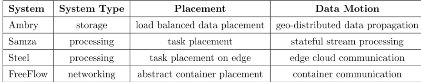
Table 1.1: Systems developed/analyzed in the thesis and the placement and data-motion notion in each.
System System Type Placement Data Motion
Ambry storage load balanced data placement geo-distributed data propagation
Samza processing task placement stateful stream processing
Steel processing task placement on edge edge cloud communication FreeFlow networking abstract container placement container communication
large scale, the state also becomes large, and a main limiting factor for both placement and movement.
In this thesis we have focused on the placement and data motion in a variety of
pro-duction systems used across multiple companies. The work spans a wide range of systems,
from a storage system, two processing systems–the traditional stream processing and the avant-garde edge processing–and a networking mechanism. We worked on transparently mitigating the challenges and requirements of a global (or sub-global) environment, includ-ing the heterogeneity, dynamism, stateful processinclud-ing and geo-distribution. This leads to our thesis:
We show how latency-driven designs for placement and data-motion can be used to buildproduction infrastructures for interactive applications at a global scale, while addressing myriad challenges on heterogeneity, dynamism, state, and availability.
A latency-driven design is an approach where achieving latency has the highest priority–
as latency is the main factor for interactivity. As suggested by the CAP theorem and its PACELC extension [11,12], there is a fundamental trade-off between consistency, availability and partition-tolerance, and in case of no failures, between latency, availability and consis-tency. In a latency-driven design, when faced with such trade-offs, the priority is given to latency. The decision of what to compromise instead, is use-case dependent, e.g., a photo sharing network would probably care for having availability of service over strong consistency. This latency-driven approach is applicable across all layers of storage, processing and
networking. Table 1.1, outlines the various systems we have developed and analyzed in this thesis, which layer they belong to, and the definition of placement and data-motion in that context. Our works spans across all layers, including:
• Storage: we have developed Ambry, a geo-distributed storage system where data placement is designed with the goal of achieving load balance, and data is constantly moved across multiple datacenters.
• Processing: we have built two processing systems, a traditional model, Samza, and the avant garde model, Steel. Samza is a stream processing system, where we place processing and support state at large scale, with the goal of minimizing data movement. Steel extends processing to the emerging edge environment with smart placement and data-motion across the entire edge-cloud environment.
• Networking: we have designedFreeFlow, a high performance networking mechanisms for containerized environments, abstracting container placements and minimizing data movement in container communications.
Figure 1.1 shows the big picture and how these various layers build the overall global system.
In the remaining of this chapter, we briefly discuss the projects, the broad impact of each system, and the intellectual merit of each.
1.1 THESIS CONTRIBUTIONS
Solving real-world problems faced by costumers has been a first class citizen in my work. Most of my work is deployed at large-scale and in mainstream production systems (e.g., Ambry and Samza) with hundreds of millions of users. In this section, we highlight the main contributions and impact of our proposed solutions.
Processing Networking DC 1 DC 2 DC n Storage Ambry Samza Steel FreeFlow Edge Edge Edge
…
Edge…
Figure 1.1: Systems studied in the thesis and their interaction. 1.1.1 Ambry: Geo-distributed Low Latency Object Storage
In today’s high-tech connected world, an immense amount of data is generated every second from all around the world. Social networks alone generated billions of variable-sized media objects per day. This excessive amount of diverse data needs to be served with low latency from all across the globe, while transparently scaling to match the ever-growing amount of data. In collaboration with LinkedIn, we developed Ambry, a geo-distributed, scalable, and low-latency object store for a broad range of objects (a few KBs to a few GBs) [13]. For over 36 months, Ambry has been themainstreamstorage for all LinkedIn’s media objects, across all of its four datacenters, serving more than 500 million users.
1.1.2 Samza: Stateful Stream Processing at Scale
When it comes to large state, relying on an external storage is not a viable solution (orders of magnitude degradation in latency and throughput). Therefore, we developed a state handling mechanism leveraging the local storage of the computing nodes [14]. Samza utilizes a partitioned local state along with a low-overhead background changelog mechanism, allowing it to scale to massive state sizes (hundreds of TB) per application. Samza is
currently in use at LinkedIn by hundreds of production applications with more than 10,000 containers while processing trillions of events per day. Samza is an open-source Apache project adopted by more than 15 companies (Uber, Netflix, TripAdvisor, etc.)
1.1.3 Steel: Optimizing and Simplifying Edge-Cloud Applications
Edge Computing is becoming a leading technology, opening the venue for a wide range of interesting applications ranging from self-driving cars, smart cities/homes, to wireless Virtual and Augmented Reality. Edges are heterogeneous, fast (near the data source), and with limited resources and bandwidth. On the other hand, the cloud is a homogeneous high(er)-latency resource. The cloud already provides a wide diversity of cloud service, e.g., streaming as a service. In this work we developed Steel that integrates the cloud and the edge into one unified geo-distributed environment [15, 16] . We support end-to-end development, deployment, and monitoring, extending cloud services to the edge. In addition, we provide optimizations for placement and communication in order to adapt to this more dynamic and heterogeneous environment. Steel is developed on top of the Azure and Windows IoT stack, and is in progress to be integrated with the production Azure code base.
1.1.4 FreeFlow: High Performance Container Networking
Containerization has piqued a strong interest in Big Data Analytics particularly because of its high portability (easily moving around), and low overhead (as they are a process on a common guest OS)[17]. However, the current cross-container networking mechanisms do not take into account the hardware capabilities (e.g. RDMA-enabled) or the locations of containers, thus, resulting in poor performance. Manual efforts to optimize networking impacts the portability to new environments. To fill this gap, we designed and developed FreeFlow, a high performance and portable container networking solution [18]. FreeFlow acts as a middle layer between the applications and underlying network, transparently choosing the optimal network option based on location (e.g., shared memory on the same host),
and hardware capabilities (e.g., use RDAM if available). FreeFlow is a general container networking technology and can be applied to any of the containerization frameworks such as Docker, Kubernetes, Mesos, YARN, CoreOS, etc. [19–23]. The team I worked with at Microsoft are analyzing adding this contribution to their production container technology.
1.1.5 Overview of Techniques
In this thesis we have focused on placement and data-motion across a wide range of system. Each system was developed with its own set of requirements fit for that system and unique set of challenges around heterogeneity and dynamism. Towards reaching interactivity while mitigating the challenges, we have employed a number of latency-driven techniques including:
1. Leveraginglocalityby preferring local data, local storage, sticky processing and location awareness. The term locality is used in the broad sense where it incorporates resource locality (e.g., stickiness to a machine or using local storage), data locality (e.g., re-access of data), and location awareness.
2. Background processing by pushing computation/data propagation to the background
out of the critical path of processing, along with optimization such as batching, com-pression and compaction.
3. Prioritizing latency over consistency and availability
4. Tiered data access along with caching, indexing, and bloom filters
5. Opportunistic processing
6. Partitioning and parallelism
Table 1.2 summarizes the main requirements and challenges in each system, and gov-erning placement and data-motion technique used to reach the goal of the system. In the following chapters we describe each system and techniques used in more detail.
1.2 RELATED WORK
This thesis argues for a latency-driven approach when building frameworks for interactive applications. We have shown this is a practical principal, employing it across a wide range of systems. As PACELC theorem proves [12], latency comes in a trade-off with availability and consistency. Others have used a similar latency-driven approach across many frameworks. The whole trend of NoSQL systems, such as Cassandra, Amazon’s DynamoDB, Pileus and others [24–27], prefer latency (in a static or dynamic manner) over consistency.
Despite the suitable fit of a latency-driven approach for interactivity, in many cases la-tency is not the only or main requirement. Sometimes, guaranteeing consisla-tency comes at higher priority, e.g., a banking system, user profile settings, and an inventory system. Many distributed storage systems, such as BigTable, Spanner, Yahoo’s PNUTS, and LinkedIn’s Espresso [28–31] support strong consistency. These consistency-driven designs typically come at cost on latency [27, 32] with techniques such as synchronous replications in multiple lo-cations (vs. lazy background), master-slave and multi-phase approaches creating extra hops in processing a request, or bottleneck-prone locking schemas with high idle times waiting for locks. Similar trends are existent in processing systems. Many stream processing frame-works, including Flink, Millwheel, Spark Streaming, and Trident [33–37], aim for “exactly-once” processing (i.e., each incoming message is processed exactly once) using complex tracking mechanism and by relying on external consistent storages.
Another approach is a resource/throughput oriented design. In cases with limited re-sources or excessive amount of data, reaching high rere-sources utilization and throughput becomes the main priority. Many batch systems (e.g., Hadoop, Spark, Tez, Pig and Hive
T able 1.2: Requiremen ts, chall enges, and solutions used in systems of this thesis with fo cus on placem en t and data-motion. System Requiremen t Challenge: Heterogeneit y Challenge: Dynamism Latency-driv en T ec h niques Am bry -geo-distributed: across m ultiple d atac en ters -state: p ersisten t and reli-able data store -la ten c y: in teractiv e shar-ing exp erience -ob ject sizes and typ es -mac hines across DCs -ob ject access pattern -links b et w een DCs and users -w orkload (diurnal, spik es) -cluster expansion -dropping p opularit y o v er time -lo calit y (lo cal data & lo cation-a w are) -bac kground pro cessing (w/ batc h ing & compaction) -prioritizing latency o v er consistency -tiered storage (w/ cac hing, indexing, & blo om filters) -partitioning a n d parallelism -load balancing Samza -state: stateful stream pro-cessing -latency: near real-time pro cessing at scale -inpu t source (batc h/stream/db) -storage option (mem, disk, remote) -op eration typ e -in put stream load changes -failures and restarts -lo calit y (lo cal storage & stic ky p ro cess-ing) -bac kground pro cessing (w/ batc h ing & compaction) -prioritizing latency o v er a v ailabilit y -tiered storage (w/ cac hing) -partitioning a n d parallelism -sc ali ng Steel -geo-distributed: across man y lo cations close to users -latency: in teractiv e pro-cessing e x p erience -edge devices -edge-c lou d net w ork -cloud services -cost/p erf mo del -p ermanen t load changes -failures and migration -short spik es -lo calit y (lo cal data & lo cation-a w are) -bac kground pro cessing (w/ batc h ing & compression) -prioritizing latency o v er a v ailabilit y -partitioning a n d parallelism F reeFlo w -latency: F ast high p erfor-mance con tainer net w orking -net w orking h ardw are’s capabilities -net w orking tec hnologies -con tainer failures or mo v e to new lo cation -lo calit y (lo cation-a w are) -prioritizing latency o v er isolation -opp ortunistic b yp as sin g
[38–42]), throughput oriented stream processing systems (e.g., Spark Streaming [36]), and high throughput storage systems (e.g., HDFS, NFS, and GFS [43–45]) have been built with this promise. Typically, throughput and resource utilization come in trade-off with latency, for example when employing approaches such as large batching, compaction, compression, and the use of slow but cheaper storage.
1.3 THESIS ORGANIZATION
The rest of the thesis is structured as follows. In the subsequent chapter we dive into each system in more detail, along with experimental evaluations for each. Chapter 2 describes the details of Ambry, a geo-distributed storage system. Chapters 3 and 4 respectively describe Samza and Steel, a stateful stream processing system and extending processing to the edge. Chapter 5 outlines FreeFlow, a high performance container technology. Finally, we conclude by presenting our future directions Chapter 6.
CHAPTER 2: AMBRY: LINKEDIN’S SCALABLE GEO-DISTRIBUTED OBJECT STORE
In this chapter we present Ambry, a geo-distributed storage system designed for managing large objects with low latency, high throughput, and in a balanced manner. The infrastruc-ture beneath a worldwide social network has to continually serve billions of variable-sized media objects such as photos, videos, and audio clips. These objects must be stored and served with low latency and high throughput by a system that is geo-distributed, highly scalable, and load-balanced. Existing file systems and object stores face several challenges when serving such large objects. We present Ambry, a production-quality system for storing large immutable data (called blobs). Ambry is designed in a decentralized way and leverages techniques such as logical object grouping abstractions, asynchronous replication, rebalanc-ing mechanisms, zero-cost failure detection, and OS cachrebalanc-ing, towards smart placement and data-motion. Ambry has been running in LinkedIn’s production environment for the past 3 years, serving up to 10K requests per second across more than 500 million users. Our experimental evaluation reveals that Ambry offers high efficiency (utilizing up to 88% of the network bandwidth), low latency (less than 50 ms latency for a 1 MB object), and load balancing (improving imbalance of request rate among disks by 8x-10x).
2.1 INTRODUCTION
During the past decade, social networks have become popular communication channels worldwide. Hundreds of millions of users continually upload and view billions of diverse massive media objects, from photos and videos to documents. These large media objects, called blobs, are uploaded once, frequently accessed from all around the world, never modi-fied, and rarely deleted. LinkedIn, as a global large-scale social network company, has faced the need for a geographically distributed system that stores and retrieves these read-heavy blobs in an efficient and scalable manner.
Handling blobs poses a number of unique challenges. First, due to diversity in media types, blob sizes vary significantly from tens of KBs (e.g., profile pictures) to a few GBs (e.g., videos). The system needs to store both massive blobs and a large number of small blobs efficiently. Second, there is an ever-growing number of blobs that need to be stored and served. Currently, LinkedIn serves more than 800 million put and get operations per day (over 120 TB in size). In the past 12 months, the request rate has almost doubled, from 5k requests/s to 9.5k requests/s. This rapid growth in requests magnifies the necessity for a linearly scalable system (with low overhead). Third, the variability in workload and cluster expansions can create unbalanced load, degrading the latency and throughput of the system. This creates a need for load-balancing. Finally, users expect the uploading process to be fast, durable, and highly available. When a user uploads a blob, all his/her friends from all around the globe should be able to see the blob with very low latency, even if parts of the internal infrastructure fail. To provide these properties, data has to be reliably replicated across the globe in multiple datacenters, while maintaining low latency for each request.
LinkedIn had its own home-grown solution called Media Server, built using network attached storage filers (for file storage), Oracle database (for metadata), and Solaris boxes. Media Server had multiple drawbacks. It faced CPU and IO spikes caused by numerous metadata operations for small objects, was not horizontally scalable, and was very expensive. Given that LinkedIn was scaling rapidly and the future web content will be largely dominated by media, it needed to find a replacement.
Several systems have been designed for handling a large amount of data, but none of them satisfactorily meet the requirements and scale LinkedIn needs. There has been extensive re-search into distributed file systems [43–47]. These systems have a number of limitations when used for storing blobs, as pointed out by [48, 49]. For instance, the hierarchical direc-tory structure and rich metadata are an overkill for a blob store and impose unnecessary additional overhead.
of objects. Although these systems can handle many small objects, they are not optimized for storing large objects (tens of MBs to GBs). Further, they impose extra overhead for providing consistency guarantees while these are typically not needed for immutable data. Some examples of these overheads include using vector clocks, conflict resolution mechanism, logging, and central coordinators.
A few systems have been designed specifically for large immutable objects including Facebook’s Haystack [48] along with f4 [51] and Twitter’s Blob Store [52]. However, these systems do not resolve load imbalance, especially when cluster expansions occur.
In this work we present Ambry1, a production-quality system designed specifically for
diverse large and small immutable data with read-heavy traffic, where data is written once, and read many times (>95% read traffic). Ambry is designed with four main goals in mind: 1. Low Latency and High Throughput: The system needs to serve a large number of requests per second in a timely fashion, while working on cheap commodity hardware (e.g., HDDs). In order to reach this goal, Ambry utilizes a number of techniques including exploiting the OS cache, using zero copy when reading data from disk to network, chunking data along with retrieving/storing chunks in parallel from multiple nodes, providing configurable polices for the number of replicas to write and read, and zero-cost failure detection mechanisms (Sections 2.2.3, 2.4.2, and 2.4.4).
2. Geo-Distributed Operation: Blobs have to be replicated in other geographically distributed datacenters for high durability and availability, even in the presence of failures. To achieve low latency and high throughput in this geo-distributed setting, Ambry is designed as a decentralized multi-master system where data can be written to or read from any of the replicas. Additionally, it uses asynchronous writes that write data to the closest datacenter and asynchronously replicate to other datacenter(s). Also, for higher availability, it uses proxy requests that forward requests to other 1Ambry is open-source and can be found at
datacenters when the data is not replicated in the current datacenter yet (Sections 2.2.3 and 2.4.2).
3. Scalability: With the ever-growing amount of data, the system has to scale out efficiently with low overhead. To achieve this goal, Ambry makes three main design choices. First, Ambry separates the logical placement of blobs from their physical placement, allowing it to change the physical placement transparently from the logical placement. Second, Ambry is designed as a completely decentralized system, with no manager/master. Third, Ambry uses on-disk segmented indexing along with Bloom filters and an in-memory cache of the latest segment, allowing for scalable and efficient indexing of blobs. (Section 2.4.4).
4. Load Balancing: The system has to stay balanced in spite of growth. Ambry uses chunking of large blobs along with a random selection approach to remain balanced in a static cluster, and a re-balancing mechanism to return to a balanced state whenever cluster expansion occurs (Section 2.3).
Ambry has successfully been in production for the last 36 months, across four datacenters, serving more than 500 million users. Our experimental results show that Ambry reaches high throughput (reaching up to 88% of the network bandwidth) and low latency (serving 1 MB blobs in less than 50 ms), works efficiently across multiple geo-distributed datacenters, and improves the imbalance among disks by a factor of 8x-10x while moving minimal data.
This chapter discusses the design and implementation of Ambry. The main contributions of this work are:
• Design and implementation of a scalable load-balanced blob Store working across dat-acenters, while maintaining low latency and high throughput.
• Evaluating various aspects of the system including latency, throughput, load-imbalance and scalability in real-world clusters.
Clu ster Manag er Replication Clu ster Manag er frontend node frontend node CDN Data Center 1 frontend node Frontend Layer
frontend nodeFrontend Node Client Clu ster Manag er http Data Layer ... Disk 1 Disk k Datanode
...
Router Library Clu ster M anag er Clu ster Manag er frontend node frontend node CDN Data Center n frontend node Frontend Layerfrontend nodeFrontend Node Client Clu ster Manag er http Data Layer ... Disk 1 Disk k Datanode Router Library
Figure 2.1: Architecture of Ambry.
• Analyzing the system over long period of time and varying workload using a simulator based on real-world data.
The rest of the chapter is organized as follows. In Section 2.2, we discuss the design and architecture of Ambry. Section 2.6 evaluates the system with a number of experimental results. Finally, we analyze the state-of-art related work in this are in Section 2.7 and conclude in Section 2.8.
2.2 SYSTEM OVERVIEW
In this section we discuss the overall design of Ambry including the high-level architec-ture of the system (Section 2.2.1), the notion of partition (Section 2.2.2), and supported operations (Section 2.2.3).
2.2.1 Architecture
Ambry is designed as a completely decentralized multi-tenant system across geographi-cally distributed data centers. The overall architecture of Ambry is shown in Figure 2.1. The
system is composed of three main components: Frontends that receive and route requests,
Datanodes that store the actual data, and Cluster Managers that maintain the state of the
cluster. Each datacenter owns and runs its own set of these components in a decentralized fashion. The Frontends and Datanodes are completely independent of one another, and the Cluster Managers are synchronized using Zookeeper [53]. We provide an overview of each component below (details in Section 2.4):
• Cluster Manager: Ambry organizes its data in virtual units calledpartitions(Section 2.2.2). A partition is a logical grouping of a number of blobs, implemented as a large replicated file. On creation, partitions are read-write, i.e., immutable blobs are read and new blobs can be added. When a logical partition reaches its capacity, it turns read-only. The Cluster Manager keeps track of the state (read-write/read-only) and location of each partition replica, along with the physical layout of the cluster (nodes and disk placement).
• Frontend: The Frontends are in charge of receiving and routing requests in a multi-tenant environment. The system serves three request types: put, get, and delete. Popular data is handled by a Content Delivery Network (CDN) layer above Ambry. Frontends receive requests directly from clients or through the CDN (if the data is cached). The Frontends forward a request to the corresponding Datanode(s) and return the response to the client/CDN originating the request.
• Datanode: Datanodes store and retrieve the actual data. Each Datanode manages a number of disks. Datanodes receive operations from Frontends and apply the opera-tions on the disks they are in charge of. For better performance, Datanodes maintain a number of additional data structures including: indexing of blobs, journals and Bloom filters (Section 2.4.4).
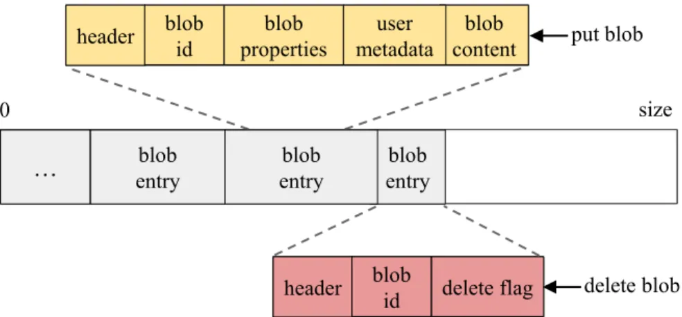
… entryblob entryblob 0 size blob content header blob properties user metadata blob id put blob
header blob id delete flag delete blob blob
entry
Figure 2.2: Partition and Blob layout. 2.2.2 Partition
Instead of directly mapping blobs to physical machines, e.g., Chord [54] and CRUSH [55], Ambry randomly groups blobs together into virtual units called partitions. The physical placement of partitions on machines is done in a separate procedure. This decoupling of the logical and physical placement enables transparent data movement (necessary for re-balancing) and avoids immediate rehashing of data during cluster expansion.
A partition is implemented as an append-only log in a pre-allocated large file. Currently, partitions are fixed-size during the life-time of the system 2. The partition size should be
large enough that the overhead of partitions, i.e., the additional data structures maintained per partition such as indexing, journals, and Bloom filters (Section 2.4.4), are negligible. On the other hand, the failure recovery and rebuild time should be small. We use 100 GB partitions in our clusters. Since rebuilding is done in parallel from multiple replicas, we found that even 100 GB partitions can be rebuilt in a few minutes.
Blobs are sequentially written to partitions as put and delete entries (Figure 2.2). Both entries contain a header (storing the offsets of fields in the entry) and a blob id. The blob id is a unique identifier, generated by the Frontend during a put operation, and used during get/delete operations for locating the blob. This id consists of the partition id in which 2As part of future work we plan to investigate potential improvements by using variable-size partitions.
the blob is placed (8 Bytes), followed by a 32 Byte universally unique id (UUID) for the blob. Collisions in blob ids are possible, but very unlikely (the probability is <2−320). For a collision to occur, two put operations have to generate equal UUIDs and chose similar partitions for the blob. Collisions are handled at the Datanodes by failing the late put request.
Put entries also include predefined properties including: blob size, time-to-live, creation time, and content type. Also, there is an optional map of user defined properties followed by the blob. Delete entries include a delete flag as an indicator of a delete entry.
In order to offer high availability and fault-tolerance, each partition is replicated on multiple Datanodes. For replica placement, Ambry uses a greedy approach based on disk spaces. This algorithm chooses the disk with the most unallocated space while ensuring constraints such as: 1) not having more than one replica per Datanode and 2) having replicas in multiple data centers. Currently, the number of replicas per partition is configurable by the system administrator. As part of future work, we plan to adaptively change the number of replicas based on the popularity of the partition, and use erasure coding for cold data to even further reduce the replication factor.
On creation, partitions are read-write, serving all operations (put, get and delete). When the partition hits its upper threshold on size (capacity threshold) it becomes read-only, thereafter serving only get and delete operations.
The capacity threshold should be slightly less than the max capacity (80-90%) of the partition for two reasons. First, after becoming read-only, replicas might not be completely in-sync and need free space to catch-up later (because of asynchronous writes). Second, delete requests still append delete entries.
Deletes are similar to put operations, but on an existing blob. By default, deletes result in appending a delete entry (with the delete flag set) for the blob (soft delete). However, Am-bry also supports hard deletes where data is overwritten with random values. Deleted blobs are periodically cleaned up using an in-place compaction mechanism. After compaction,
… Frontend Router Library Client … Data node i Disk ... Disk Data node k Disk ... Disk 3 3 1 3 p Data node j Disk ... Disk 4 4 5 2: Choose 4
Figure 2.3: Steps in processing an operation.
read-only partitions can become read-write if enough space is freed-up. In the rest of the chapter we mainly focus on puts, due to the similarity of delete and put operations.
2.2.3 Operations
Ambry has a lightweight API supporting only 3 operations: put, get, and delete. The request handling procedure is shown in Figure 2.3. On receiving a request, the Frontend optionally conducts some security checks on the request. Then, using the Router Library (that contains the core logic of operation handling) it chooses a partition, communicates with the Datanode(s) in charge, and serves the request. In the put operation, the partition is chosen randomly (for data balancing purposes), and in the get/delete operation the partition is extracted from the blob id.
Operations are handled in a multi-master design where operations can be served by any of the replicas. The decision of how many replicas to contact is based on user-defined poli-cies. These policies are similar to consistency levels in Cassandra [24], where they control how many (one, k, majority, all) replicas to involve in an operation. For puts (or deletes), the request is forwarded to all replicas, and policies define the number of acknowledgments
needed for a success (trade-off between durability and latency). For gets, policies deter-mine how many randomly selected replicas to contact for the operation (trade-off between resources usage and latency). In practice, we found that for all operations thek = 2 replica policy gives us the balance we desire. Stricter polices (involving more replicas) can be used to provide stronger consistency guarantees.
Additionally, performing write operations to all replicas placed in multiple geo-distributed datacenters in a synchronous fashion can affect the latency and throughput. In order to alleviate this issue, Ambry uses asynchronous writes where puts are performed synchronously only in the local datacenter, i.e., the datacenter in which the Frontend receiving the request is located. The request is counted as successfully finished at this point. Later on, the blob is replicated to other datacenters using a lightweight replication algorithm (Section 2.5).
In order to provide read-after-write consistency in a datacenter which a blob has not been replicated yet (e.g., writing to one datacenter and reading from another), Ambry uses proxy requests. If the Frontend cannot retrieve a blob from its local datacenter, it proxies the request to another datacenter and returns the result from there. Although a proxy request is expensive, in practice we found that proxy requests happen infrequently (less than 0.001 % of the time).
2.3 LOAD BALANCING
Skewed workloads, massively large blobs, and cluster expansions create load imbalance and impact the throughput and latency of the system. Ambrytries to achieve balance in terms of two factor a) disk usage and b) request rates. We study load balancing in two cases: astatic cluster where nodes and disks are not added or deleted and adynamic cluster
2.3.1 Load Balancing a Static Cluster
In a static cluster Ambry uses a combination of three simple techniques: random place-ment, chunking, and caching. By routing put operations to random partitions, it is expected to have a balanced number of puts per partition. By splitting large blobs into multiple small chunks, it is expected to have an balance size across blobs, thus, overall reaching a balance in terms of the overall data stored at each partition and the disk usage. However, this does not mean balanced request rates across disks. Ambry relies on caching, in a CDN layer above it, to serve the extremely hot and outlier blobs. Since partitions are fairly large, with millions of blobs per partition, partitions have a similar distribution of data, especially since the hot outliers are served outside of Ambry. Using these techniques the load imbalance of request rates and partition sizes in production gets to as low as 5% amongst Datanodes.
2.3.2 Load Balancing a Dynamic Cluster
In practice, read-write partitions receive all the write traffic and also the majority of the read traffic (due to popularity). Since partitions grow in a semi-balanced manner, the number of read-write partitions becomes the main factor of load imbalance. After cluster expansion, new Datanodes contain only read-write partitions, while older Datanodes contain mostly read-only partitions. This skewed distribution of read-write partitions creates a large imbalance in the system. In our initial version, the average request rates of new Datanodes were up to 100x higher than old Datanodes and 10x higher than the average-aged ones.
To alleviate this issue, Ambry employs a rebalancing mechanism that returns the cluster to a semi-balanced state (in terms of disk usage and request rate) with minimal data move-ment. The rebalancing approach reduces request rate and disk usage imbalance by 6-10x and 9-10x respectively.
Ambry defines the ideal (load balanced) state as a triplet (idealRW, idealRO, idealUsed) representing the ideal number of read-write partitions, ideal number of read-only partitions
and ideal disk usage each disk should have. This ideal state (idealRW, idealRO, idealUsed) is computed by dividing the total number of read-write/read-only partitions and total used disk space by the number of disks in the cluster, respectively. A disk is considered above (or below) ideal if it has more (or less) read-write/read-only partitions or disk usage than the ideal state.
The rebalancing algorithm attempts to reach this ideal state. This is done by moving partitions from disks above ideal to disks below ideal using a two-phase approach, as shown in the pseudo-code below.
Algorithm 2.1 Rebalancing Algorithm
1: // Compute ideal state.
2: idealRW=totalNumRW / numDisks
3: idealRO=totalNumRO / numDisks
4: idealUsed=totalUsed / numDisks
5: // Phase1: move extra partitions into a partition pool.
6: partitionP ool ={} 7: foreach diskddo
8: // Move extra read-write partitions.
9: while d.N umRW > idealRWdo
10: partitionP ool += chooseM inimumU sedRW(d)
11: // Move extra read-only partitions.
12: while d.N umRO > idealRO & d.used> idealUseddo
13: partitionP ool += chooseRandomRO(d)
14: // Phase2: Move partitions to disks needing partitions.
15: placePartitions(read-write)
16: placePartitions(read-only)
17: function placePartitions(Type t)
18: while partitionP ool contains partitions typet do
19: D=shuffleDisksBelowIdeal()
20: fordiskdin Dand partitionp in pool do
21: d.addPartition(p)
22: partitionP ool.remove(p)
Phase1 - Move to Partition Pool: In this phase, Ambry moves partitions from disks above ideal into a pool, called partitionPool (Lines 6-13). At the end of this phase no disk
should remain above ideal, unless removing any partition would cause it to fall below ideal. Ambry starts from read-write partitions (which are the main factor), and moves extra ones solely based on idealRW threshold. The same process is repeated for read-only par-titions, but with considering both idealRO and idealUsed when moving partitions. The strategy of choosing which partition to move is based on minimizing data movement. For read-write partitions, the one with the minimum used capacity is chosen, while for read-only partitions, a random one is chosen since all such partitions are full.
Phase2 - Place Partitions on Disks: In this phase, Ambry places partitions from the partition pool on disks below ideal (Lines 14-16), starting from read-write partitions and then read-only ones. Partitions are placed using a random round-robin approach (Line 17-22). Ambry finds all disks below ideal, shuffles them, and assigns partitions to them in a round-robin fashion. This procedure is repeated until the pool becomes empty.
After finding the the new placement, replicas are seamlessly moved by: 1) creating a new replica in the destination, 2) syncing the new replica with old ones using the replication protocol while serving new writes in all replicas, and 3) deleting the old replica after syncing. Although the rebalancing algorithm has low complexity, moving data around can impact the performance of the system. Thus, we are working on performing rebalancing in the background when the load of the system is low, e.g., overnight.
2.4 COMPONENTS IN DETAIL
In this section we further discuss the main components of Ambry. We describe the detailed state stored by the Cluster Manager (Section 2.4.1), extra responsibilities of Fron-tends including chunking and failure detection (Section 2.4.2), and additional structures maintained by the Datanodes (Section 2.4.4).
Table 2.1: Hardware layout in Cluster Manager.
Datacenter Datanode Disk Size Status
DC 1 Datanode 1 disk 1 4 TB UP ... ... ... diskk 4 TB UP DC 1 Datanode 2 disk 1 4 TB DOWN ... ... ... diskk0 4 TB UP ... ... ... ... DC n Datanode j disk 1 1 TB DOWN ... ... ... diskk00 1 TB UP 2.4.1 Cluster Manager
The Cluster Manager is in charge of maintaining the state of the cluster. Each datacenter has its local Cluster Manager instance(s) kept in-sync with others using Zookeeper. The state stored by the Cluster Manager is very small (less than a few MBs in total), consisting of a hardware and logical layout.
Hardware Layout
The hardware layout includes information about the physical structure of the cluster, i.e., the arrangement of datacenters, Datanodes, and disks. It also maintains the raw capacity and status, i.e., healthy (UP) or failed (DOWN), for each disk. An example hardware layout is shown in Table 2.1. As shown, Ambry works in a heterogeneous environment with different hardware and configuration used inside and across different datacenters.
Logical Layout
Partitions act as logical placeholders for blobs such that blobs are mapped to partitions completely unaware of the physical placement. Each partition has number of replicas, where
Table 2.2: Logical Layout in Cluster Manager.
Partition id State Placement
partition 1 read-write DC 1: Datanode 1: disk 1 DC 1: Datanode 4: disk 5 ... DC 3: Datanode 7: disk 2 partition 2 read-only DC 1: node 1: disk 1 ... DC 3: node 5: disk 1 ... ... ... partitionp read-only DC 1: Datanode 1: disk 1 ... DC 4: Datanode 5: disk 2
each replica is placed on a disk. The logical layout maintains the physical location of partition replicas, and the state (read-only/read-write) of each partition. In order to find the state of a partition, the Cluster Manager periodically contacts the Datanodes, and requests the state of their partitions. This layout is used for choosing a partition to write a new blob to (put operation), and locating the Datanode in charge of a given replica (all operations). An example of this layout is shown in Table 2.2. As shown, replicas of a partition can be placed on multiple Datanodes in one datacenter, and/or in different datacenters. Additionally, one disk (e.g., DC 1: Datanode 1: disk 1) can contain replicas of distinct partitions, where some are read-only and some are read-write. Partitions are added by updating the logical layout stored in the Cluster Manager instances3.
2.4.2 Frontend Layer
The Frontend is the entry point to Ambry for external requests. Each datacenter has its own set of Frontends. Frontends are decentralized involving no master or coordination, 3Currently, the system administrator manually adds partitions in order to prevent unwanted and rapid
identically performing the same task, and stateless with all state stored in the Cluster Man-ager (which is periodically pulled). This design enhances scalability (new Frontends can be added without much performance penalty), fault-tolerance (requests can be forwarded to any Frontend), and failure recovery (failed Frontends can quickly be replaced) for Frontends. Frontends have three main responsibilities:
1. Request Handling: This involves receiving requests, routing them to the corresponding Datanode(s) using the Router Library and sending back the response.
2. Security Checks: Optionally performing security checks, such as virus scanning and authentication on requests.
3. Capturing Operations: Pushing events to a change capture system out of Ambry for further offline analysis, such as finding request patterns of the system. We use Kafka [56] as our change-capture system due to the high durability, high throughput, and low overhead it provides.
At the core of the Frontend is the Router Library which actually performs the routing. Upon receiving a request, the Frontend performs security checks, logs the operation, uses the Router Library to route the request, and returns the response from the Router Library back to the user. The following section discusses the details of the Router Library, and the functionalities it supports.
2.4.3 Router Library
The Router Library contains all the core logic of handling requests and communicating with Datanodes. Frontends simply embed and use this library. Clients can bypass Frontends by embedding this library and directly serving requests. This library includes four main procedures: A) policy-based routing, B) chunking large blobs, C) failure detection, and D) proxy requests.
# Chunks
ChunkId1
partitionId UUID
ChunkIdk
partitionId UUID
...
Figure 2.4: Content of the metadata blob used for chunked blobs.
A. Policy Based Routing: On receiving a request, the library decides which partition to involve (randomly chosen for puts and extracted from blob id for gets/deletes). Then, based on the policy used it communicates with the corresponding replica(s) until the request is served/failed. It supports a variety of policies including{one, k, majority, all}, as discussed in Section 2.2.3.
B. Chunking: Extremely large blobs (e.g., videos) create load imbalance, block smaller blobs, and inherently have high latency. To mitigate these issues, Ambry splits large blobs into smaller equal-size units called chunks. A large chunk size does not fully resolve the large blob challenges and a small chunk size adds too much overhead. Based on our current large blob size distribution, we found the sweet spot for the chunk size to be in the range of 4 to 8 MB4.
During a put operation, a blob b is split intok chunks {c1, c2, ..., ck}, each treated as an independent blob. Each chunk goes through the same steps as a normal put blob operation (Section 2.2.3), most likely being placed on a different partition. It is also assigned a unique chunk id with the same format as a blob id. In order to be able to retrieveb Ambry creates a metadata blobbmetadata forb. bmetadata stores the number of chunks and chunk ids in order, as shown in Figure 2.4. This metadata blob is then put into Ambry as a normal blob and the blob id of bmetadata is returned to the user as the blob id of b. If the put fails before writing all chunks, the system will issue deletes for written chunks and the operation has to 4Chunk size is not fixed and can be adapted to follow the growth in blob sizes, improvements in network,
available
wait period
temp down
temp
available
wait period
temp down
temp
available
available
Figure 2.5: Failure detection algorithm with maximum tolerance of 2 consecutive failed responses.
be redone.
During a get, the metadata blob is retrieved and chunk ids are extracted from it. Then, Ambry uses a sliding buffer of size s to retrieve the blob. Ambry queries the first s chunks of the blob independently and in parallel (since they are most likely written on unique partitions placed on separate Datanodes). When the first chunk in the buffer is retrieved, Ambry slides the buffer to the next chunk, and so on. The whole blob starts being returned to the user the moment the first chunk of the blob is retrieved.
Although an extra put/get is needed in this chunking mechanism (for the metadata blob), overall, our approach improves latency since multiple chunks are written and retrieved in parallel.
C. Zero-cost Failure Detection: Failures happen frequently in a large system. They range from unresponsiveness and connection timeouts, to disk I/O problems. Thus, Ambry needs a failure detection mechanism to discover unavailable Datanodes/disks and avoid forwarding requests to them.
Ambry employs a zero-cost failure detection mechanism involving no extra messages, such as heartbeats and pings, by leveraging request messages. In practice, we found our failure detection mechanism is effective, simple, and consumes very little bandwidth. This mechanism is shown in Figure 2.5. In this approach, Ambry keeps track of the number of
consecutive failed requests for a particular Datanode (or disk) in the last check period of time. If this number exceeds a MAX FAIL threshold (in our example set to 2) the Datanode is marked as temporarily down for a wait period of time. In this state all queued requests for this Datanode will eventually time out and need to be reattempted by the user. After the wait period has passed, the Datanode becomes temporarily available. When a Datanode is in the temporarily available phase, if the next request sent to that Datanode fails, it will move to the temporarily down phase again. Otherwise, it will be marked as available, working as normal again.
D. Proxy Requests: As described in Section 2.2.3, Ambry uses proxy requests to reach higher availability and read-after-write consistency in remote datacenters. When a blob has not been replicated in the local datacenter yet, requests for that blob are forwarded to other datacenters and served there (proxy requests). However, datacenter partitions can cause unavailability of unreplicated data until the partition is healed and replicas converge.
Proxy requests are handled by the Router Library, transparently from the user issuing the request. In practice, we found proxy requests occur less than 0.001% of the time, thus minimally affecting the user experience.
2.4.4 Datanode Layer
Datanodes are in charge of maintaining the actual data. Each Datanode manages a number of disks, and responds to requests for partition replicas placed on its disks. Puts are handled by writing to the end of the partition file. Gets can be more time-consuming, especially since the location of the blob in the partition is not known. To minimize both read and write latencies, Datanodes employ a few techniques:
• Indexing blobs: Ambry stores an index of blob offsets per partition replica to prevent
• Exploiting OS cache: Ambry utilizes OS caching to serve most reads from the RAM, by limiting the RAM usage of other components.
• Batched writes, with a single disk seek: Ambry batches writes for a particular partition
together and periodically flushes the writes to disk. Thus, it incurs at most one disk seek for a batch of sequential writes. The flush period is configurable and trades off latency for durability. Although, batching can introduce overheads of flushing, dirty buffers, and tuning, the benefits outweigh these overheads.
• Keeping all file handles open: Since partitions are typically very large (100 GB in
our setting), the number of partition replicas placed on a Datanode is small (a few hundred). Thus, Ambry keeps all file handles open at all times.
• Zero copy gets: When reading a blob, Ambry utilizes a zero copy [57] mechanism, i.e.,
the kernel directly copies data from disk to the network buffer without going through the application. This is feasible since the Datanodes do not perform any computation on the data at get operations. Note that data read from disk is usually old and less popular. A significant advantage of zero copy is that it also helps toward better utilizing the OS cache by not copying less popular data into it.
These few simple techniques have significantly improved the latency and throughput in Ambry. As we show in 2.6.1, we are able to reach 75%-88% of the maximum network bandwidth by using these techniques. Below, we discuss two of these techniques (indexing and OS Caches) in more detail.
Indexing
To find the location of a blob in a partition replica with low latency, the Datanode maintains a light-weight in-memory indexing per replica, as shown in Figure 2.6. The indexing is sorted by blob id, mapping the blob id to the start offset of the blob entry. The indexing is updated in an online fashion whenever blobs are put (e.g., blob 60) or deleted (e.g., blob 20).
blob id 40 … 850 900 0 100 GB
Partition
blob id 20 200 blob id 60 980 … end offset blob id 20 1040 blob id 70 Index segment 1 Index segment 2 Index segment 3 Start offset: 700 End offset: 1020blob id offset flags TTL
20 980 del -40 850 - ∞ 60 900 - ∞ 70 700 - 1/2/2017 700
Index
start offset of currentindex segment
Figure 2.6: Indexing of blob offsets in a partition replica. When blobs are put (blob 60) or deleted (blob 20) the indexing stucture is updated.
Similar to SSTables [28], Ambry limits the size of the index by splitting it into segments, storing old segments on disk, and maintaining a Bloom filter for each on-disk segment.
The indexing also stores a flag indicating if a blob has been deleted and optionally a time-to-live (TTL). During get operations, if the blob has expired or been deleted, an error will be returned before reading the actual data.
Note that the indexing does not contain any additional information affecting the correct-ness of the system, and just improves performance. If a Datanode fails, the whole indexing can be reconstructed from the partition.
Exploiting The OS Cache
Recently written data, which is the popular data as well, is automatically cached without any extra overhead (by the operating system). By exploiting this feature, many reads can be served from memory, which significantly improves performance. Thus, Ambry limits
the memory usage of other data structures in the Datanode. Ambry bounds the indexing by splitting it into segments, with only the latest segment remaining in-memory (Figure 2.6). New entries are added to the memory segment of the indexing. When the in-memory segment exceeds a maximum size it is flushed to disk as a read-only segment. This design also helps toward failure recovery since only the in-memory segment needs to be reconstructed. Looking up blob offsets is done in reverse chronological order, starting with the latest segment (in-memory segment). Thus, a delete entry will be found before a put entry when reading a blob. This ensures deleted blobs are not retrievable.
Bloom Filters: To reduce lookup latency for on-disk segments, Ambry maintains an in-memory Bloom filter for each segment, containing the blob ids in that index segment. Using Bloom filters, Ambry quickly filters out which on-disk segment to load. Thus, with high probability, it incurs only one disk seek. However, due to our skewed workload a majority of reads just hit the in-memory segment, without any disk seeks.
2.5 REPLICATION
Replicas belonging to the same partition can become out of sync due to either failures, or asynchronous writes that write to only one datacenter. In order to fix inconsistent replicas, Ambry uses an asynchronous replication algorithm that periodically synchronizes replicas. This algorithm is completely decentralized. In this procedure each replica individually acts as a master and syncs-up with other replicas, in an all-to-all fashion. Synchronization is done using an asynchronous two-phase replication protocol as follows. This protocol is a pull-based approach where each replica independently requests for missing blobs from other replicas.
• First Phase: This phase finds missing blobs since the last synchronization point. This is done by requesting blob ids of all blobs written since the latest syncing offset and then filtering the ones missing locally.
offset blob id 700 70 850 40 900 60 980 20 offset blob id 600 30 670 55 750 40 800 70 950 90 Journal of partition p, replica r1 Journal of partition p, replica r2 latestOffset r2= 600
1. get blob ids after 600 2. ids ={55, 40, 70, 90} 3. filter out missing blobs
4. get blobs {55, 90} 5. blob 55 and blob 90
6. write blobs and set latestOffset r2= 950
Figure 2.7: Journals for two replicas of the same partition and an example of the replication algorithm.
• Second Phase: This phase replicates missing blobs. A request for only the missing blobs is sent. Then, the missing blobs are transferred and appended to the replica. In order to find the recently written blobs quickly, the replication algorithm maintains an additional data structure per replica, called ajournal. The journal is an in-memory cache of recent blobs ordered by their offset. The journal is the inverse of the Indexing table. It can promptly return which new blobs have been added since a given offset.
Figure 2.7 shows example journals of two replicas (r1andr2) and the two phase replication
procedure for r1 syncing with r2 from latestOffset 600. In the first phase, r1 requests all
recently added blobs in r2 after latestOffset; using the journal r2 returns a list B ={55, 40,
70, 90}of blob ids; andr1 filters out the missing blobs (blob 55 and 90). In the second phase,
r1 receives the missing blobs, appends the blobs to the end of the replica, and updates the
journal, indexing and latestOffset.
This replication protocol is periodically used in an all-to-all fashion between each pair of replicas. The overall replication procedure is shown in the algorithm below. Since it is desirable to minimize cross-datacenter traffic, replication algorithm is used separately for
so that, with high probability, only one replica receives data from another datacenter and replicates the data inside the datacenter, instead of multiple cross datacenter replications. Algorithm 2.2 Replication Algorithm
1: for each partition p replicar1 do
2: for each remote replicar2 of p do
3: BlobIds = get blob IDs (latestOffset[r2])
4: M issingIds = find missing blobs(BlobIds)
5: Blobs=get blobs(M issingIds)
6: writeBlobs(Blobs)
7: update indexing()
8: update journal()
9: update last offset(r2)
To provide improved efficiency and scalability of the system, the replication algorithm employs a number of further optimizations:
• Using separate thread pools for inter- and intra-datacenter replication with different periods.
• Batching requests between common partition replicas of two Datanodes, and batching blobs transferred across datacenters.
• Batching blobs transfered across datacenters
• Prioritizing lagging replicas to catch up at a faster rate (by using dedicated threads for lagging replicas).
2.6 EXPERIMENTAL RESULTS
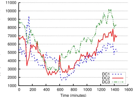
We perform three kinds of experiments: small cluster (Section 2.6.1), production cluster (Section 2.6.2), and simulations (Section 2.6.3). We divide our evaluation into three parts, each focusing on one of the main goals in Ambry. First we evaluate the latency and through-put of the system. Second, we show the effectiveness of our multi-colo optimizations and last we analyze the load-balancing mechanism over time.
2.6.1 Throughput and Latency
In this section we measure the latency and throughput of the system using a micro-benchmark that stress-tests the system, under read-only, write-only and read-write work-loads.
Micro-Benchmark: We first measure the peak throughput. We designed a micro-benchmark that linearly adds load to the system (by adding more clients), until the satura-tion point where no more requests can be handled. Each client sends requests one at a time with the next request sent right after a response.
This benchmark has three modes: Write, Read, and ReadWrite. In Write mode, random byte array blobs are being put by varying number of clients. In Read mode, first blobs are written at saturation rate for a write-period of time. Then, randomly chosen blobs are read from the written blobs5. In most experiments we set the write-period long enough that
most read requests (> 80%) are served by disk, rather than RAM. Read-Write is a similar to Read, but serving 50% reads and 50% writes after the write-period. Since latency and throughput are highly correlated with blob size, we use fixed-size blobs in each run, but vary the blob size.
Experimental Setup: We deployed Ambry with a single Datanode. The Datanode was running on a 24 core CPU with 64 GB of RAM, 14 1TB HDD disks, and a full-duplex 1 Gb/s Ethernet network. 4 GB of the RAM was set aside for the Datanode’s internal use and the rest was left to be used as Linux Cache. We created 8 single-replica 100 GB partitions on each disk, with a total of 122 partitions. Using 14 disks with a 1 Gb/s network might look like an overkill. However, disk seeks are the dominant latency factor for small blobs. Since a large portion of blobs are small (<50 KB), we need the parallelism created by using multiple disks. Note that Ambry is designed as a cost-effective system using cheap HDD disks.
5The random strategy gives a lower bound on the system’s performance since real-world access patterns
Clients send requests from a few machines located in the same datacenter as the Datan-ode. These clients, that are acting as Frontends, directly send requests to the DatanDatan-ode. The micro-benchmark discussed above was used with varying blob sizes{25 KB, 50 KB, 100 KB, 250 KB, 500 KB, 1 MB, 5 MB}. We did not go above 5 MB since blobs are chunked beyond that point.
Effect of Number of Clients
We ran the micro-benchmark with varying blob sizes, while linearly increasing the number of clients. For Read mode, the write-period was set such that 6 times the RAM size, was first written. Figure 2.8a shows the throughput in terms of MB/s served by the system. Adding clients proportionally increases the throughput until the saturation point. Saturation occurs at 75%-88% of the network bandwidth. The only exception is reading small blobs due to frequent disk seeks (more details in following sections). Saturation is reached quickly (usually ≤ 6 clients) since clients send requests as fast as possible in the benchmark.
Figure 2.8b shows the latency normalized by blob size (i.e., average latency divided by blob size). Latency stays almost constant before reaching saturation point, and then in-creases linearly beyond the throughput saturation point. The linear increase in latency after saturation indicates the system does not add additional overhead beyond request serving.
Effect of Blob Size
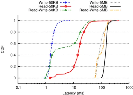
In Figures 2.9a and 2.9b we analyzed the maximum throughput (with 20 clients) under different blob sizes and workloads. For large objects (>200 KB), the maximum throughput (in MB/s) stays constant and close to maximum network bandwidth across all blob sizes. Similarly, throughput in terms of requests/s scales proportionally.
However, for Read and Read-Write, the read throughput in terms of MB/s drops linearly for smaller sizes. This drop is because our micro-benchmark reads blobs randomly, incurring frequent disk seeks. The effect of disk seeks is amplified for smaller blobs. By further
0 20 40 60 80 100 120 140 0 5 10 15 20 Throughput (MB/s) Number of Clients 5MB-Write 500KB-Write 50KB-Write 5MB-Read 500KB-Read 50KB-Read Network BW (a) Throughput 0 0.1 0.2 0.3 0.4 0.5 0.6 0.7 0.8 0 2 4 6 8 10 12 14 16 18 20 Normalized Latency (ms) Number of Clients Write 5MB
Write 500KB Write 50KBRead 5MB Read 500KBRead 50KB
(b) Latency normalized by blob size
Figure 2.8: Throughput and latency of read and write requests with varying number of clients on different blob sizes. These results were gathered on a single Datanode
10 100 1000 10 100 1000 10000 Max Throughput (MB/s) Blob Size (KB) Write Read Read-Write Network (a) Throughput (MB/s) 10 100 1000 10000 10 100 1000 10000
Requests Per Second
Blob Size (KB) Write Read Read-Write Network (b) Throughput (requests/s) 1 10 100 10 100 1000 10000 Average Latency (ms) Blob Size (KB) Write Read Read-Write (c) Latency
Figure 2.9: Effect of blob size on maximum throughput, both in terms of MB/s and requests/s, and latency. Results were gathered on a write-only, read-only, and mixed (50%-50%) workload. Reads for small blob sizes (<200 KB) are slowed down by frequent disk seeks, while other requests saturate the network link.