Int. J. Electrochem. Sci., 11 (2016) 8571 – 8580, doi: 10.20964/2016.10.21
International Journal of
ELECTROCHEMICAL
SCIENCE
www.electrochemsci.org
Effect of Electrolyte Composition on Zn Electrode in Weak
Acidic Aqueous Electrolyte
Zhuan Hu, Yongli Li, Jingyu Gu, Jinqing Kan*
School of Chemistry and Chemical Engineering, Yangzhou University, Yangzhou, 225002, China *
E-mail: [email protected]
Received: 8 July 2016 / Accepted: 16 August 2016 / Published: 6 September 2016
The electrochemical behavior of zinc and polyaniline (PANI) obtained by the oxidative polymerization of aniline in 1.0 M aqueous HC1 by (NH4)2S2O8 were investigated in ZnCl2 + NH4Cl (chloride electrolyte), (NH4)2SO4 + ZnSO4 (sulfuric acid electrolyte), and (NH4)2SO4 + ZnSO4 + (CH3COO)2Pb ( acetic acid electrolyte) with the addition of Na-citrate and Na-malonate. Compared with sulfuric acid electrolyte and acetic acid electrolyte, zinc electrode shows the minimum of charge transfer resistance (Rct) and lower corrosion current densities, and polyaniline (PANI) keep high electrochemical activity in the chloride electrolyte at pH 4.0. The formation of zinc dendrite and the hydrogen evolution of the zinc electrode were suppressed in chloride electrolyte. The potentials were limited to 1.5 V for charge and to 0.7 V for discharge at 50 mA g-1, obtained the initial discharge specific capacity of 109.5 mAh g-1, the columbic efficiency remained at around 100% after 1000 times charge-discharge cycles.
Keywords: zinc,polyaniline, dendrites, aqueous electrolyte, rechargeable batteries
1. INTRODUCTION
Zinc is the most widely used metal as the anodes of the primary batteries for its good electrochemical performances, abundant resource and low sensitivity to moisture [6, 7]. Zinc-based batteries are very attractive in both primary and secondary battery systems, such as Zn-MnO2, Zn-air and Zn-PANI batteries [8]. PANI is a conventional conductive polymer, which has attracted considerable attention because of its good redox reversibility, high conductivity and environmental stability [9-11]. These excellent features make it as an interesting candidate for electrode materials in electrical energy storage devices, including supercapacitors [12] and rechargeable batteries [13]. Zn/PANI rechargeable batteries showed many excellent characteristics compared with the conventional batteries, high reversible energy density (50–100Wh kg−1), good columbic efficiency (70–100%), low self-discharge rate and long cycle life [14-16]. However, the life-time of the Zn-PANI battery is highly dependent on the pH of the electrolyte [17]. For zinc electrode easily provoke corrosion in the pH <4.0 while the activity of the conducting polymers (PANI) is limited at higher pH. Therefore, the interval of pH 4.0 - 5.5 is generally chosen as a trade-off between a decreased electrochemical activity of PANI at higher pHs and increased Zn corrosion in acidic electrolytes [18, 19]. On the other hand, the cycle-life of the Zn–PANI rechargeable battery is limited by the anode (zinc), the polarization resistance (Rp) of the Zn electrode increases with cycling [20]. In electrolytes containing only chloride, Zn electrodes usually easily formed dendrites during charge–discharge. Zinc dendrites can penetrate the separator and reach the counter electrode, which results in short-circuiting and decreased cycle life [21, 22]. At the same time, Zn electrode surface hydrogen evolution when using aqueous electrolytes (generally, pH<4) during cyclization [23]. If the corrosion on the Zn anode can be prevented, crucial improvements in the Zn/PANI rechargeable batteries will be achieved.
Many organic anions can form complexes with the metal ions. Lee et al. [24] reported that the order of increase in hydrogen overpotential is tartaric acid > succinic acid > phosphoric acid > citric acid, and the prevention of dendrite formation follows the order of citric acid > succinic acid > tartaric acid > phosphoric acid in 8.5M KOH electrolyte. Jugović et al. [25] reported that the decrease of exchange current density and the increase of deposition overpotential, which result in lower rate dendrite formation and zinc corrosion, in chloride/citrate-contained electrolyte.
In the present study, we further investigated the behavior of the zinc and PANI electrodes in chloride electrolyte, sulfuric acid electrolyte and acetic acid electrolyte containing the Na-citrate and Na-malonate at pH 4.0. The characteristic of Zn and PANI electrodes will be given.
2. EXPERIMENTAL
2.1 Materials
2.2 The Preparation of electrode
PANI was prepared by chemical polymerization from a solution of 1.0 M hydrochloric acid, 0.2 M aniline and the mole ratio of ammonium persulfate to aniline was 1. The mixtures were stirred by a magnetic stirrer and cooled to 0 - 5 0C, then (NH4)2S2O8 was slowly dropped into the aqueous solution at 0 - 5 0C. After stirring at 5 0C for 1 h, the temperature of the reaction system was gradually raised to room temperature. After 5 h of polymerization, the resulting precipitate was repeatedly filtered and washed to remove monomers by doubly distilled water, and the oligomers were removed by ethanol. The synthesized PANI was dried under vacuum at 80 0C for 48 h. Finally, the polyaniline was sieved through an 80 mesh stainless-steel sieve after grinding.
The work of zinc electrode: First, cutting zinc sheet with 10 mm × 100 mm. Then, zinc sheets were mechanically polished with fine emery papers to remove oxides on its surface. Next, polished by alumina on the polishing cloths. Finally, the traces of polishing alumina were removed from the electrode surface in an ultrasonic bath in ethanol for 5 min.
2.3 The Preparation of electrolyte
All experiments were performed at ambient temperature in electrolytes composed of 0.5M (NH4) 2SO4 + 0.2M ZnSO4, or 0.5M NH4Cl + 0.2M ZnCl2 or 0.5M (NH4) 2SO4 + 0.2M (ZnSO4) + 510-4M (CH3COO)2Pb) with the addition of the same concentration sodium citrate and sodium malonate, respectively. All used electrolytes prepared using doubly distilled water at pH 4.0.
2.4 Preparation of the battery
The negative electrode in the Zn-PANI rechargeable battery was consisted of a zinc sheet with a working area of 10 cm2. The positive electrode consisted of quantitative acetylene black, carboxymethyl cellulose (CMC) and PANI powder mixtures was pressed on the 50 mesh stainless steel (0.5 mm in thickness) at 10 MPa by using a flat vulcanizing machine. The electrodes were separated by the polypropylene non-woven fabrics and mounted in a transparent vessel containing electrolyte as a battery. The electrolyte in batteries was an aqueous electrolyte of 0.2 M ZnCl2 and 0.5M NH4Cl (pH 4.0) with the addition of Na-citrate and Na-malonate.
2.5 Apparatus
reference, working and counter electrodes, respectively. All potentials are referred to the SCE. The cyclic voltammograms of the zinc electrode were recorded at 50 mV s-1 in the different electrolytes. The superimposed sinusoidal voltage signal was set up to 10 mV amplitude. Data were collected within the frequency range from 105 to 10-1 Hz. Tafel curves were carried out at 50 mV s-1 in the different electrolytes within the potential range from -1.5 V to -0.4 V. The surfaces of the zinc sheet were observed by three-dimensional surface contourgraph scanning ( NanoMap - 500LS, AEP - Technology Inc) and the surface morphologies of the zinc sheet were confirmed using a scanning electron microscope (SEM, SUPRA 55-4828, Germany).
3. RESULTS AND DISCUSSION
3.1 Zinc electrode
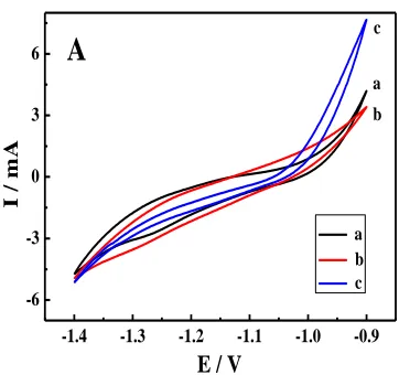
Figure1 shows the cyclic voltammograms (CVs) of the Zn electrodes in chloride electrolyte, sulfuric acid electrolyte, and acetic acid electrolyte, respectively. The potential range was from -1.4V to -0.9V at pH 4.0. It can be seen that three curves are somewhat similar in a shape and almost the same redox potentials in different electrolytes. Curve (a) and curve (b) has a similar enclosed area while the curve (c) was one well defined enclosed area with the maximum current peak, and better symmetry compared with other curves. Although, Grgur [26] thought that the improvement of zinc properties was due to zinc ions complexation with citrate in the electrolyte containing citrate. In fact, further research is needed for the real reason of improving zinc properties, which is not immediately clear exactly. It is advantageous for the secondary battery with large current response and good dissolving and deposition reversibility in chloride electrolyte. It is also beneficial to improve the performance of the Zn-PANI rechargeable batteries.
-1.4 -1.3 -1.2 -1.1 -1.0 -0.9
-6 -3 0 3
6
A
b c
a
a b c
E / V
I
/
m
A
Figure 1. CV of Zn electrode in electrolyte: (a) (NH4)2SO4 + ZnSO4, (b) (NH4)2SO4+ ZnSO4 + (CH3COO)2Pb, (c) NH4Cl + ZnCl2. Scan rate: 50mV s-1.
[image:4.596.203.384.507.677.2]
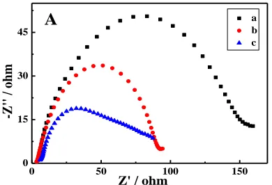
Zn electrode in chloride electrolyte, sulfuric acid electrolyte, or acetic acid electrolyte at pH 4.0. Each curve corresponds to a semicircle in the high frequency region. These semicircles could be used to evaluate the value of the electrochemical charge transfer resistance (Rct). The curve (a) with (NH4)2SO4 + ZnSO4 and curve (b) with (NH4)2SO4+ ZnSO4 + (CH3COO)2Pb electrolytes have the larger Rct, while the Rct value of the curve (c) with NH4Cl + ZnCl2 is much lower than others. The smaller Rct shows that the electrode surface reaction process is faster, which is more beneficial to the charge - discharge of the large current [28]. So it is more suitable as the zinc-polyaniline battery electrolyte.
0 50 100 150
0 15 30
45 A
Z' / ohm
a b c -Z '' / o h m
Figure 2. EIS of Zn electrodes in electrolytes: (a) (NH4)2SO4 + ZnSO4, (b) (NH4)2SO4+ ZnSO4 + (CH3COO)2Pb, (c) NH4Cl + ZnCl2.
Figure 3 shows the Tafel plots of Zn electrode in three electrolytes. Tafel plot plays an important role to characterize the anticorrosion of metal material, the higher the Ecorr (corrosion potential) and the lower Icorr (corrosion current) is, the anticorrosion of electrode material is the better [29]. According to Figure 3, corrosion potential, corrosion current and Tafel slopes were listed in the Table 1. From Table 1 and Figure 3, the Zn electrode has obviously higher Ecorr and lower Icorr in the electrolyte (NH4Cl + ZnCl2) than what in the other two kinds of electrolytes. So the Zn electrode in the electrolyte (NH4Cl + ZnCl2) is more stable than that in the other two kinds of electrolytes.
-1.6 -1.4 -1.2 -1.0 -0.8 -0.6 -0.4
[image:5.596.196.391.223.356.2]-6 -5 -4 -3 -2 -1 0
B
c lg (c u r r e n t( A )) Potential(V vs.SCE) a b c a [image:5.596.184.402.548.710.2]
Table 1. Corrosion potential (Ecorr) , corrosion current (Icorr), Tafel slope of Zn electrode in different electrolytes
Names ba
(dec·V -1)
bc (dec·V -1)
Icorr×104 (A)
Ecorr (V vs. SCE)
Curve a 28.5 13 3.21 -1.087
Curve b 18.5 11 2.60 -1.061
Curve c 17 14.5 1.32 -1.060
ba (dec·V-1): anodic Tafel slope; bc (dec·V-1): cathodic Tafel slope; Ecorr (V vs.SCE): corrosion potential; I corr (A ): corrosion current
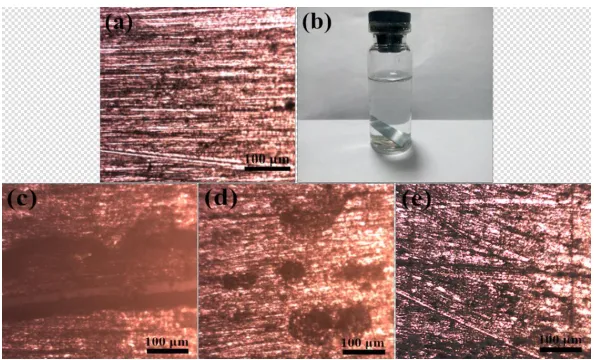
The micrographs of the Zn electrodes soaked in chloride electrolyte, sulfuric acid electrolyte, and acetic acid electrolyte were shown in Figure 4. The new polished the scratches on Zn surface is clearly observed (Figure 4 (a)). Figure 4 (b) is the sketches of Zn sheet soaked in three different electrolytes. Under the same conditions, the polished Zn sheets were soaked in different electrolyte for 30days. The scratches of the Zn electrode soaked in electrolyte (ZnSO4 + (NH4)2SO4) can not be seen clearly (Figure 4 (c)); the scratches of the Zn electrode soaked in electrolyte (NH4)2SO4+ ZnSO4 + (CH3COO)2Pb is rather vague (Figure 4 (d)); However, the scratches of the Zn electrode soaked in electrolyte ZnCl2 + NH4Cl can be clearly seen (Figure 4 (e)). It is suggested that the Zn electrode soaked in electrolyte ZnCl2 + NH4Cl has the best corrosion resistance performance.
Figure 4. Micrographs of new polished the Zn electrode (a) the polished of Zn electrode in the electrolyte (b) Zn electrode for 30d in the three different electrolyte: (c) ZnSO4 + (NH4)2SO4, (d) (NH4)2SO4+ ZnSO4 + (CH3COO)2Pb, (e) ZnCl2 + NH4Cl.
3.2 PANI electrode
[image:6.596.150.447.427.607.2]
that polyaniline has a relatively high charge-discharge specific capacity in the electrolyte (0.5 M NH4Cl + 0.2M ZnCl2) with pH 4.0. High specific capacity is very important for an aqueous Zn-PANI rechargeable battery.
-0.2 0.0 0.2 0.4 0.6 0.8
-8 -4 0 4
8 c
b
a b c
I
/
m
A
E / V
a
A
Figure 5. CV of PANI electrode in electrolyte: (a) (NH4)2SO4 + ZnSO4, (b) (NH4)2SO4+ ZnSO4 + (CH3COO) 2Pb, (c) NH4Cl + ZnCl2.Scan rate: 50mV s-1.
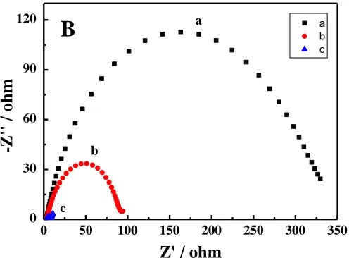
Figure 6 shows the Nyquist plots of the PANI electrode in three different electrolytes. All the Nyquist plots consist of a semicircle and a line. The semicircle in the high frequency region was mainly related to charge transfer resistance (Rct) and double-layer capacitance [30]. The straight line in the low frequency region is on behalf of the Warburg impedance of PANI, which indicates the reaction is controlled by interface diffusion between the electrolyte and the electrode [31]. As it can be seen that the charge transfer resistance of PANI in the electrolyte (NH4Cl + ZnCl2) is minimal. The smaller Rct shows that the faster electrode process, hence, the electrolyte (NH4Cl + ZnCl2) is more suitable used for aqueous Zn -PANI rechargeable battery.
0 50 100 150 200 250 300 350
0 30 60 90 120
B
-Z
''
/
o
h
m
c b
a a
b c
[image:7.596.184.409.140.288.2]Z' / ohm
[image:7.596.169.417.515.698.2][image:8.596.112.472.228.381.2]
3.3 Charge and discharge of Zn/PANI rechargeable battery
Figure 7 is the charge and discharge plots of the Zn-PANI battery in the 0.5 M NH4Cl + 0.2M ZnCl2 with the addition of Na-citrate and Na-malonate electrolytes. The PANI initial discharge specific capacity was 109.5 mAh g-1, which is higher than that of the polyaniline (89.9 mAh g−1, reported by Zhaoling Ma) [32] and the coulombic efficiency still kept about 100 % between 0.7 V and 1.5 V for over 1000 cycles (Figure 7(A)), which shown that the battery possess good reversible in the electrolyte.
Figure 7. The charge and discharge cycles on the performance of the Zn/PANI battery, (A) coulomb efficiency charge and discharge curve (B) 15th cycle, at a constant current of 50 mA g-1, pH 4.0.
The surface micrographs of the zinc sheet was shown in Figure 8 over 1000 times charge and discharge cycles. It is seen from the Figure 8 that the zinc dendrite was obviously suppressed. It indicates that the chloride electrolyte containing Na-citrate and Na-malonate is more suitable as aqueous zinc-polyaniline rechargeable battery electrolyte.
[image:8.596.180.416.536.709.2]
4. CONCLUSIONS
Studies on the Zn and polyaniline electrodes clearly demonstrated that NH4Cl + ZnCl2 electrolyte with addition Na-citrate and Na-malonate have potential advantages as Zn-PANI rechargeable battery electrolyte. The dendrite formation and the hydrogen evolution of the zinc electrode were suppressed in the chloride electrolyte containing Na-citrate and Na-malonate. Meanwhile, PANI electrode shows satisfactory electrochemical activity. The discharge specific capacity of the polyaniline is as high as 109.5 mAh g-1in the aqueous NH4Cl + ZnCl2 electrolyte. It means that the aqueous chloride electrolyte containing Na-citrate and Na-malonate is more suitable as zinc-polyaniline rechargeable battery electrolyte.
ACKNOWLEDGEMENTS
This project was supported by the National Science Foundation of China (No.20873119), and by the Priority Academic Program Development of Jiangsu Higher Education Institutions. Part of the data was from the Testing Center of Yangzhou University.
References
1. Z. Chang, Y.Q. Yang, M.X. Li, X.W. Wang, Y.P. Wu, J. Mater. Chem. A 2 (2014) 10739 2. Y. Li, H. Dai, Chem. Soc. Rev. 43 (2014) 5257
3. S. Li, K. Shu, C. Zhao, C. Wang, Z. Guo, G. Wallace, H. K. Liu, Acs. Appl. Mater. Inter. 6 (2014) 16679
4. Y. G. Huang, J. Chen, X. H. Zhang, Y. H. Zan, X. M. Wu, Z. Q. He, Q. Y. Li, Chem. Eng. J. 296 (2016) 28
5. W. Si, X.Wu, J. Zhou, F. Guo, S. Zhuo, H. Cui, Nanoscale Res. Lett. 8 (2013) 1
6. C. Chen, X. Hong, A. Chen, T. Xu, L. Lu, S. Lin, Y. Gao, Electrochim. Acta 190 (2016) 240 7. A. Guerfi, J. Trottier, I. Boyano, I. De Meatza, J. A. Blazquez, S. Brewer, K. Zaghib, J. Power
Sources 248 (2014) 1099
8. S. Wu, Y. Zhao, D. Li, Y. Xia, S. Si, J. Power Sources 275 (2015) 305 9. Z. Jing, S. Dan, S.Mu, Polymer 48 (2007) 1269
10. Y. Zhao, S. Si, C. Liao, J. Power Sources 241 (2013) 449 11. J. Han, L. Wang, R. Guo, J. Mater. Chem. 22 (2012 ) 5932 12. A. A. Kalam, J. E. Yoo, J. Bae Polym. Test. 44 (2015) 49
13. Y. Tao, K. Rui, Z. Wen, Q. Wang, J. Jin, T. Zhang, T. Wu, Solid State Ionics 290 (2016) 47 14. M. Sima, T. Visan, M. Buda, J. Power Sources 56 (1995) 133
15. E. M. Genies, P. Hany, C. Santier, J. Appl. Electrochem. 18 (1988) 751 16. Z. Mandić, M. K. Roković, T. Pokupčić, Electrochim. Acta 54 (2009) 2941
17. M. S. Rahmanifar, M. F. Mousavi, M. Shamsipur, M. Ghaemi, J. Power Sources 132 (2004) 296 18. U. S. Waware, M. Rashid, J. Adv. Phys 3 (2014) 29.
19. S. Mu, Synthetic Met. 143 (2004) 259.
20. B. C. Dalui, I. N. Basumallick, S. Ghosh, Indian J. Chem. Techn. 15 (2008) 576
21. J. Huang, Z. Yang, R. Wang, Z. Zhang, Z. Feng, X. Xie, J. Mater. Chem. A 3 (2015) 7429 22. M. Xu, D. G. Ivey, W. Qu, Z. Xie, J. Power Sources 274 (2015) 1249
23. T. K. Hoang, K. E. K. Sun, P. Chen, RSC Adv. 5 (2015) 41677
25. B. Z. Jugović, T. L. Trišović, J. S. Stevanović, M. D. Maksimović, B. N. Grgur, Electrochim. Acta 51 (2006) 6268
26. B. N. Grgur, J. Adv. Eng. Sci 1 (2007) 21
27. K. Ghanbari, M. F. Mousavi, M. Shamsipur, H. Karami, J. Power Sources 170 (2007) 513 28. Z. Jugović, T. Lj. Trišović, J. S. Stevanović, M. M. Gvozdenović, B. N. Grgur. J. Appl.
Electrochem. 39 (2009) 2521.
29. H. Xu, J. Zhang, Y. Chen, H. Lu, J. Zhuang, J. Solid State Electr. 18(2014) 813
30. H. Tang, Y. Ding, C. Zang, J. Gu, Q. Shen, J. Kan, Int. J. Electrochem. Sci. 9 (2014) 7239 31. Y. Li, Z. Hu, Y. Ding, J. Kan, Int. J. Electrochem. Sci. 11 (2016) 1898
32. Z. Ma, J. Kan, Synthetic Met. 174 (2013) 58
![Figure 7 is the charge and discharge plots of the Zn-PANI battery in the 0.5 M NH4ZnClspecific capacity was 109.5 mAh greported by Zhaoling Ma) [32] and the coulombic efficiency still kept about 100 % between 0.7 V and 1.5 V for over 1000 cycles (Figure 7(](https://thumb-us.123doks.com/thumbv2/123dok_us/1848080.141294/8.596.112.472.228.381/figure-discharge-znclspecific-capacity-greported-zhaoling-coulombic-efficiency.webp)
![Synthesis of Li[Li0.2Mn0.54Ni0.13Co0.13]O2 Cathode Material in Acetate System for Lithium-Ion Battery](data:image/gif;base64,R0lGODlhAQABAIAAAP///wAAACH5BAEAAAAALAAAAAABAAEAAAICRAEAOw==)