Abstract: A modified version of fuel injector with higher injection capacity has been developed. To achieve this, the injector plunger diameter is increased to 11mm from current 9.5mm. A new test rig is developed to understand the functioning of the injector due to the changes incorporated. The new test rig is designed to test injector operation without burning the fuel. Since internal combustion is not present an external arrangement is required to run the engine. This is achieved through a 3-phase induction motor, which is coupled with the crankshaft of the engine. The injected fuel is collected form the cylinders and it is then recirculated. A fuel cooling circuit is also incorporated along with the fuel recirculation system to maintain the temperature of fuel at inlet of fuel pump. An oil heating system is installed in the test rig to maintain the viscosity of the oil by heating it. The required systems for driving the engine, fuel cooling and oil heating are implemented as per the design. The test is conducted on a 19 L diesel engine. Parts which are not required for this test like piston, piston rings, intake and exhaust manifold etc are removed from the engine. And the cylinder liner is blocked from below using a plate to facilitate the collection of injected fuel. Engine is made to run using the motoring rig at the rated speed of 1500 rpm for a duration of 250 hours. Instrumented push tubes are used to measure the push tube load. Push tube load is observed to be in the range of 2700 to 3100 lbf, which is high as compared to the earlier model of the injector. Fuel injection rate is obtained from the fuel collected from the cylinders. And the average fuel injection rate is observed as 0.116 to 2.35 kg/min. Thus, the increase in plunger diameter has led to an increase in fuel injection rate.
Index Terms: Fuel injector testing, motoring rig, oil heating system, fuel cooling circuit.
I. INTRODUCTION
The performance of diesel engines is highly influenced by the design of the injection system. Most of the advances achieved in diesel engines resulted directly from superior fuel injection system designs. Hence automotive industries have always focused on modifying the fuel injector design and testing them to evaluate their impact on engine performance, emissions, and noise characteristics. Fuel injector testing devices having in-built high-pressure pump and removable cam have been developed, so that injectors of different sizes can be tested in the same apparatus [1,2]. Testing methods are developed to observe fuel leakage from injector, fuel flow condition, fuel spray pattern etc [3,4]. To test the spray pattern, rather than fuel other test fluids under selected
Revised Manuscript Received on July 9, 2019.
Sreejyothi R, Department of Mechanical Engineering, Amrita School of Engineering, Amrita Vishwa Vidyapeetham, Coimbatore, India
D Senthilkumar, Department of Mechanical Engineering, Amrita School of Engineering, Amrita Vishwa Vidyapeetham, Coimbatore, India
pressure can be used [5]. Devices which performs number of tests to check the ability of the fuel delivery system to maintain pressure, to determine the static and dynamic flow rates through each of the fuel injectors in the fuel system are developed. It also determines the ability of the fuel system to deliver sufficient fuel during wide-open throttle operation [6]. Researches have been done on on electrical wiring harness for testing the fuel injection system of an internal combustion engine so that each individual fuel injector is then selectively disabled and their functioning can be tested. Operation of the engine before and after disabling individual fuel injectors are compared to detect whether any of the injectors are malfunctioning [7]. Also, to check the malfunctioning of injectors on-board diagnostic system are present, which works based on the transient pressure wave signals from the fuel rail [8]. Studies are made to measure the rate of fuel injection, nature of cavitation which could occur in the near nozzle region. This is done by analyzing the temporal signature of the pressure signals that arise in a typical injection cycle [9].
The test methods have been designed to evaluate injector deposit effects on performance in real world driving conditions. And the effect of different fuel additive levels in maintaining injector cleanliness and therefore power and fuel economy was compared in a light duty vehicle [10]. Injector cavitation detection tests are conducted using compressed gas and sensors to detect the pressure output signals [11]. And injector drift for a diesel engine are detected by reconfiguration of injection patterns from one pattern into a pattern with a different number of pulse points while attempting to hold total fuel injected constant [12].
Injector testing is also done using test oil, which is circulated with a fluid pump mechanically connected to a motor. The fluid pump, the motor, and the rail configured to receive the test oil, are supported elastically in the injector testing device as a common assembly [13]. Researches have been done in developing a fuel injector assembly for an engine system which includes a fuel pressurization mechanism, a fuel injector, and a flow - directing sleeve positioned about the fuel injector. In this assembly fuel is used to cool the fuel pressurization mechanism, and more particularly to a flow - directing sleeve structured to direct a flow of the cooling fuel into and out of the fuel injector [14]. Fuel injectors are developed with headers in which a sensor is implemented to measure one or more parameters of the fuel injector during operation. These measured parameters can be processed and analyzed to provide diagnostics of the operation or condition and other characteristics of the fuel injector [15].
Fuel Injector Testing Through Development of a
New Test Rig
II. BACKGROUNDANDOBJECTIVES A modified version of fuel injector with higher injection capacity has been developed. To achieve this, the injector plunger diameter is increased to 11 mm from current 9.5 mm. Since the fueling rate has increased there is an increase in the load on push tubes. These two parameters are of great importance in determining the failure modes and durability of the fuel injector. Therefore, these parameters need to be measured.
A new test rig is developed to understand the functioning of the injector due to the changes incorporated. The main objective of this project is to develop a new test rig to test fuel injector operation without burning the fuel. The test set up is designed and all the required systems are installed as per the design. The fuel injection rate due to the increased plunger diameter (11mm from current 9.5mm) and the push tube loads due to increased loading are measured using this newly developed rig.
III. DESIGNOFNEWTESTRIG
A. Set Up Requirements in New Test Rig
The test cell requires a base rail and mountings to install the 19L diesel engine. Motor is needed to run the engine and mountings are required to place the motor in line with the crank shaft. In order to connect the shaft of motor to the engine crank shaft coupling must be used. An integrated variable frequency drive system is inevitable to control the speed of the motor. Since fuel is not being burned, it will be circulated during the test. So, fuel circulation system with provision to cool the fuel and maintain its temperature is mandatory. To maintain the viscosity of the lubricating oil, it needs to be heated. Therefore, an oil heating system must be installed in the test cell. Since the fuel injected in each cylinder is measured separately provision for collecting the injected fuel is also needed. And to measure the push tube loads, instrumented push tubes are being used. Hence an Indicom trolley is needed to collect the data from instrumented push tubes.
B. Layout of Test Rig
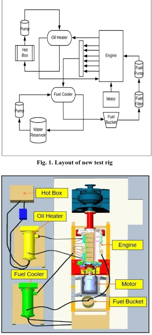
The layout for the test cell is designed in such a way that there are provisions for running the engine using a motor, fuel circulation, fuel cooling and oil heating requirements. A 50 HP motor is coupled with the crankshaft of the engine to run it without burning the fuel. Base rails for installing the engine as well as mountings for placing the motor are designed. Fuel from all cylinders are collected by blocking the cylinder liner with a plate. A threaded hole is provided in the cylinder liner are hoses are connected to it. All six hoses from six cylinders are directed to a common channel from where another hose is connected to allow the flow of collected fuel into the heat exchanger. Once the temperature of the fuel is reduced to required range of 90-120 ⁰Fahrenheit, fuel flows into a fuel bucket having capacity of 100 L. From the bucket fuel is recirculated through the fuel filter and fuel pump into the fuel injection lines. For absorbing the rejected heat from the fuel, water is being circulated through the heat exchanger, from the water reservoir.
Engine oil is mandatory to lubricate the moving parts in the engine. And for maintaining the viscosity of the oil it needs to be heated. Since internal combustion is not present a heat
[image:2.595.308.552.101.373.2]exchanger connected with a hot box is required for doing this process. Thus, the oil heating circuit helps in maintaining the oil pan temperature in the range of 70-200 ⁰ Fahrenheit.
Fig. 1. Layout of new test rig
Fig. 2. Top view of the designed test rig C. Motor and Mountings
[image:2.595.306.551.107.647.2]And to connect the shaft of the motor with the crank shaft coupling is needed. Since flex tyre couplings are highly elastic, lubrication free couplings that can tolerate large amount of misalignment in all planes as well as offering simple installation and inspection without disrupting the drive, it is used to connect the shafts. The misalignment capability of flex tyre coupling is 4° angular, up to 6mm parallel and 8mm axial.
[image:3.595.45.287.161.548.2]Fig. 3. CREO model of motor and mountings
Fig. 4. Motor installed in test rig
D. CREO Model of Total Test Set Up
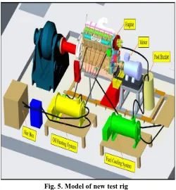
Test cell with fuel circulation and cooling system, oil heating system, motoring rig, provisions to collect the fuel from each cylinder is designed and modelled using CREO software.
Fig. 5. Model of new test rig
IV. IMPLEMENTATIONOFTESTSETUP
A. Modifications Made in the Engine
[image:3.595.46.288.162.348.2]Engine used for testing is an inline 6-cylinder 19L diesel engine. The rated power is 450 – 600 HP at 1500 rpm. The weight of the engine is 2799 kg. This engine is used for railway as well as generator applications. Certain parts like piston sub assembly, intake manifold, exhaust manifold, damper and pulley etc which are not required for execution of this test are removed from the engine. To collect the injected fuel from cylinder, the cylinder liner is blocked from bottom using a plate. And a handle is also incorporated on the plate to facilitate the placement and removal of liner from the cylinder. During the execution of the test fuel dilution is observed due to leakage from the blocking plate in cylinder liner. Hence as a corrective action araldite is used to seal the gap between the liner and the blocking plate.
[image:3.595.307.551.540.716.2]B. Engine Installed in Test Rig
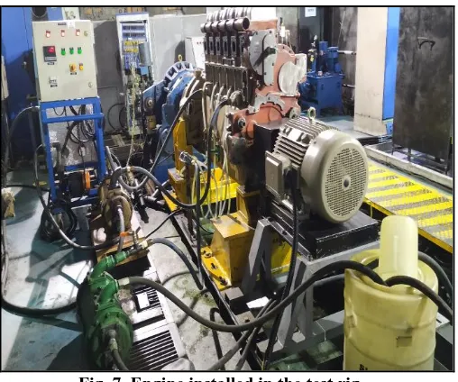
[image:4.595.47.301.349.561.2]As per the design of the new test rig, the motor and the mountings are installed in the test cell. Tyre coupling is used to couple the engine crankshaft with the motor shaft. A variable frequency drive is connected to the motor to control the speed of the motor. Engine is also installed on the engine mounting rails, fuel cooling and re-circulation circuit connections, oil heating circuit connections are implemented. From the instrumented push tubes connection are given to the Indicom trolley to collect the data regarding push tube load
.
Fuel is collected from each cylinder and directed towards a common channel. Braided fuel hoses are used to make these connections. A heat exchanger is added in this circuit to reduce the temperature of the recirculated fuel. And water is used as the cooling fluid. A 100 L bucket is used to collect the fuel coming out from the engine. From the fuel bucket connections are given back to the fuel pump on the engine.
Oil from the engine is collected and circulated through a heat exchanger to heat it to the required oil pan temperature. Oil pan side plate is drill tapped and sensor is installed in it to measure the temperature of the oil in oil pan. The required minimum temperature is 70⁰ F. In this circuit a hot box is added to heat the water and hot water serves as the heating liquid in the heat exchanger.Fig. 7. Engine installed in the test rig
V. TESTDETAILS
Motor is started at lower rpm (100-200 rpm) with crankshaft coupled to it and run the engine for 15 minutes. Gradually speed is increased to 500 rpm. Oil rifle pressure, oil pan temperature and fuel rail pressure are to be checked. Oil pan temperature shall be monitored. Oil pan temperature of at least 70⁰ F need to be achieved before the motor is taken to 1500 rpm. Motor speed is set to 1500 rpm and the oil pan temperature, fuel filter in temperature and fuel rail pressure are observed. Fuel from any one cylinder will be collected for a time-period of 5 mins to calculate the fuel injection rate. Push tube load will be measured using instrumented push tubes assembled on the engine. Test will be conducted for a duration on 250 hours.
VI. RESULTSANDDISCUSSION
A. Rate of Fuel Injection
Fuel is collected from the cylinders which are blocked at the bottom. Fuel from each cylinder is collected separately during the test. The graph shows an average value of fuel injection rate in all 6 cylinders. The value of fuel injection is found to be in the range of 0.116 to 2.35 kg/min
.
Graph 1: Fuel injection rate Vs time for one cycle
Graph 2: Fuel injection rate Vs time for 10 cycles
B. Push Tube Load
Push tube load is measured from the instrumented push tubes assembled in the engine. The average value of 6 push tubes are shown in the graph. Push tube load in LBF and engine speed in rpm is plotted against time in minutes. The graph shows one cycle of the test which is around 2.6 hours. Similar cycles are repeated for 250 hours. The value of push tube load is obtained in the range of 2700 LBF to 3100 LBF.
Graph 3: Push tube load Vs time for one cycle
Graph 4: Push tube load Vs time for 10 cycles
C. Oil Pan Temperature
Graph 5: Oil pan temperature Vs time for one cycle
Graph 6: Oil pan temperature Vs time for 10 cycles
Oil pan temperature is measured by the J type temperature sensor kept on the oil pan side plate. Oil pan temperature is observed in the range of 80 to 230⁰F. Only when the oil pan temperature goes above 70⁰F the engine is taken to rated rpm. And by using a shell and tube heat exchanger the oil pan temperature is maintained in the required range.
D. Fuel Pump Inlet Temperature
Fuel pump inlet temperature is measured using a J type temperature sensor. It is used to ensure that temperature is maintained at the required level during the fuel recirculation. Fuel cooling system helps in maintain this temperature. Its value is in the range of 80 to 105⁰F.
Graph 8: Fuel pump inlet temperature Vs time for 10 cycles
VII. CONCLUSION
Fuel injector testing is done in test cell under simulated conditions using a motoring rig, to obtain parameter like fuel injection rate, push tube loads etc. Push tube load is observed to be in the range of 2700 to 3100 lbf, which is high as compared to the earlier model of the injector. So further trials with actual combustion of fuel is required to measure the push tube loads in actual engine running conditions. During execution of the test higher vibration is observed on push tubes. Hence vibration trials need to be conducted on this engine with this modified injector.
Average fuel injection rate is observed as 0.116 to 2.35 kg/min. The increase in plunger diameter has led to an increase in fuel injection rate. Since the fuel injection rate is high cylinder head temperature measurement and peak cylinder pressure measurement needs to be done. This also leads to a possibility of plunger scuffing and oil dilution. Hence further trials are required to study the effects on plunger surface. Also, oil dilutions trials need to be done at highest power rating
.
REFERENCES
1. Reginald Stanley Emerson (26th July,1977). Fuel injector testing apparatus. US Patent. Patent number 4,037,467.
2. Arthur M. Needham (24th December,1985). Testing device for fuel injectors. US Patent. Patent number 4,559,815.
3. James R. Koslow (4th June,1985). Fuel injection cleaning and testing system and apparatus. US Patent. Patent number 4,520,773.
4. Leonard Lieberman (6th December ,1988). Fuel Injector Testing Device and Method.US Patent, Oldsmobile Chassis Service Manual, vol. II, pp. 6E-130 to 6E-133.
5. Jeffrey H. Young (15th December,1987). Fuel Injector Testing Device. US Patent. Patent number 4,712,421.
6. George R. Hart,Charles J. Nehoda ; (4th June, 1991). Fuel Injection System Tester. US patent; patent number 5,020,362.
7. J. Nicholas Smith; (Apr. 28, 1992). Fuel injector testing harness. US Patent, patent number 5,107,701.
8. John M. Glidewell, Granger K.-C. Chui, Woong-Chul Yang (16th July,1996). On-board detection of fuel injector malfunctioning. US Patent. Patent number 5,535,621.
9. Yannis Hardalupas (9th June 2015). Near Nozzle Field Conditions in Diesel Fuel Injector Testing. SAE Technical Paper 2015-24-2470, 2015, doi:10.4271/2015-24-2470.
10. Christiane Behrendt., Alastair Smith (28th March 2017) A Study of Diesel Fuel Injector Deposit Effects on Power and Fuel Economy Performance. SAE Technical Paper 2017-01-0803, 2017, doi:10.4271/2017-01-0803.
11. Paul Curtis, Raymond Mueller (18th July 2017). Injector Cavitation Detection Test. US Patent, patent number US 9,709,012 B2.
12. Nirav Atul Shah, Mark Brian Michelotti, Sumeet Suresh Yerunkar (28th March 2017). Method for analyzing injector performance. US Patent. Patent number US 9,605,611 B2.
13. Reinhard Hoss Armin Batha,; Daniel Strack .,( 20th Sept 2018). Injector Testing Device. US patent, patent number US 2018 / 0266378 A1.
14. Robert Campion, George Kodikulam Joseph, Satya Naga Deepak Pillarisetti and Zhenyu Li (22nd May 2018). Fuel injector assembly having sleeve for directing fuel flow. US Patent, patent number US 9,976 , 527 B1.
15. David Thomas, Mike Archer, Cornelia Schulz, Florian Langguth (24th May, 2018). Fuel injector including sensor. US Patent. Patent number US 2018 / 0142655 A1.
16. Nikhil Tom Varghese, D.Senthilkumar, M.Vivek, “Studyon Effects of Magnetization of Fuel on Diesel Engine " International Journal of Applied Engineering Research, Volume 10, Number 17 pp 37866-37870(2015)
17. Siddhartha Prabhakar.N, D.Senthil Kumar “Study on Performance and Emission Characteristics of a Diesel Engine by Preheating the Intake Air through Exhaust Heat Recovery” “International Journal of Applied Engineering Research. Vol 10, No. 85 (2015).
18. R.Vishnu Varthan and D.Senthil Kumar, “Emission Characteristics of Turbocharged Single Cylinder Diesel Engine”, Indian Journal of Science and Technology, Vol 9(17), May 2016.( ISSN (Print) : 0974-6846)
AUTHORSPROFILE
Ms.Sreejyothi R,
M.Tech in Engineering Design, Amrita School of Engineering, Coimbatore. B.Tech in Mechanical Engineering from Kerala University. Published a paper in Engine testing work flow analysis.