Strategy for Flawless Transfer of Islanded and Grid
Connected Modes with Modifed Droop Controller
A.Sheela, S.Revathi, S.Ragul,
Abstract: Technical advances in power electronics and generation capabilities have made the possibility of Distributed Generation (DG) systems. A microgrid is an effective division of a distributed generation system which is analysed by its capability of its operation both as a grid connected and isolated condition. All independent sources operate separately when the main grid is capable of supporting voltage. In case of islanded mode, dynamics is greatly influenced by the connected sources and on the power handling ability. Control of power interfaced converters is of major concern in both the modes of operation. In grid connected mode of operation, the current of the voltage developed needs to be controlled whereas, in Isolated condition, building of voltage is required.In the islanded mode of operation, all the resources in a microgrid should be controlled in coordination with each other so that a stable and a balanced three-phase sinusoidal voltage is obtained. Conventional droop controller is modified for accurate sharing among power converters even when the measured voltage and frequency of the inverters are not the same. Droop coefficients are estimated so that power sharing is more accurate for the respective changes in the power values. They also enable the flawless transfer of the operation mode from islanded to grid connected or vice versa.
Key words:Microgrid, grid connected mode, Islanded mode, droop coefficients
I. INTRODUCTION
Normally, grid connected mode is carried by the microgrids, but it is also anticipated that it may need to operate in islanded mode at any time. It is expected from the microgrid that it has to provide the necessary generation ,and control at least to part of the load during islanded mode because load would be disconnected from the main grid. In grid connection, almost all the system behavior depends on the main grid and the microgrid has less significance during this mode because of its lower capacity. During this mode, good quality of active and reactive power is transported by controlling active and reactive components of current. So, the interfaced converter acts as current source in this mode of operation. Main grid balances the power mismatch instantly thereby maintaining system frequency and voltage.
n contrast, during the islanded mode, the interface converter acts as a voltage source since the voltage has to be built by the converters. Change of controller is required when there is transition from one mode to another. It is more important to have a flawless transfer of controller from one mode to another. Another important aspect is the active and reactive power flow control and regulation of voltage and frequency.
Revised Manuscript Received on September 03, 2019
Dr.A.Sheela, Department of EEE,Kongu Engineering College Erode, India,[email protected]
Ms.S.Revathi, Kongu nadu college of Engineeringand
technology, [email protected]
Mr.S.Ragul, Kongu nadu college of Engineeringand
technology, Trichy.
All the coordinated systems work with Active and Reactive power (PQ) control strategy because the reference power is available. DGs supply constant power in this mode of operation. Islanded mode of operation would cause large power mismatches creating problems. So, in islanded mode of operation, microgrid operates in V/f or droop control for compensating power and for controlling voltage and frequency. This mode of microgrid depends highly on the integration of DGs and on the controller of the interface converters. Droop control
shares reactive and active power without proper communication. Total Harmonic Distortion (THD) is a major problem in microgrids. THD values within the grid has to be maintained low as per standards. H∞ repetitive controller is used to design the voltage and current loops for obtaining low THD[1]. Obtaining low THD values in any one mode is not a difficult task. Simultaneous control for obtaining low THD to attain flawless transfer by varying the base values to the controller is proposed.
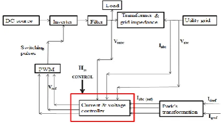
An Estimated Droop Controller (EDC) is proposed, in which the coefficients are estimated depending on the demanded power and output power of the inverter. Improvement in power quality indices like voltage and frequency magnitude maintained within nominal values and reduction in THD are also targeted. H∞ repetitive controller is used for voltage and current loop design. Figure 1 shows the overall block diagram of the proposed method. Based on the operating mode signal, a proper control technique has to be chosen. System is assumed to be in grid mode when the switch is in closed condition and act as a constant source. During this mode it injects required power. The system is in isolated mode when the switch is in open condition. During fault all renewable sources are to be disconnected for supplying reliable power. The major issue is the power control and the voltage control.
Strategy for Flawless Transfer of Islanded and Grid Connected Modes with Modifed Droop Controller
II. CONTROL STRATEGY FOR GRID CONNECTED MODE
[image:2.595.50.265.215.354.2]In grid connected mode, microgrid operates in PQ control strategy wherein the direct axis and quadrature axis currents are proportional to power. Therefore by proper control of these components, power can be controlled. Figure 2 shows the diagram of interface converters in the grid connected mode. DGs can supply poweronly if the electrical parameters at the point of common coupling are within specified limits. Under normal condition, microgrid works in grid mode and the power can be matched simulataneously. System voltage and frequency are supported in this way.
[image:2.595.316.543.319.445.2]Figure 2 Control structure of grid connected mode (Green et al. 2007)
Figure 3 shows the block diagram of the processes involved in the control of the grid connected mode.
Figure 3 Block diagram of grid connected mode For controlling PQ of the inverter, as shown in the above figure, Park’s transformation converts all the voltage and currents at the main grid into rotating frame. The current components are generated from the reference real and reactive power. By controlling those components, powers through an inverter can be controlled. The reference currents for predetermined power settings
P
ref andQ
ref are given byd ref dref
V
P
i
(1)d ref qref
V
Q
i
(2)The reference current is converted into three phase quantity using Clarke’s transformation. The output reference voltage obtained by the voltage and current loop is given to the PWM inverter which provides switching pulses to the inverter.
III. CONTROL STRATEGY FOR ISLANDED
MODE
The objective of islanded mode is to establish the required voltage while that of the grid connected mode is to control the current. When a disturbance occurs in the main grid, sometimes intentionally, the switch opens ,and the microgrid operates in islanding mode. In islanding operation mode, due to the inqdequate supply from the main grid, the power mismatch has to be meet out by the DGs to supply loads, and to maintain power quality. The frequency is changed and it is determined by the droop coefficients of DGs when mode transition occurs. For maintaining frequency within nominal values, determination of droop coefficients should be properly done. DGs are made to operate in V/f control for maintaining voltage and frequency at nominal values. In isolated mode, the sources with PQ strategy the voltage and frequency references are not developed which would be present if it is under grid connected mode. PQ control strategy changes to VF strategy. The power mismatch is compensated through the main grid before islanding.Figure 4 reveals the diagram for the total processes.
Figure 4 Block Diagram of the islanded mode control DGs share power by the droop. Power values are calculated from instantaneous voltage and current.
IV. DROOP CONTROL FOR ACTIVE AND
REACTIVE POWER SHARING
The theory which lies behind droop theory is the speed governor of synchronous generator. Load increase is affected by frequency reduction. Reactive power is proportional to the voltage. Same thing is followed in droop characteristics. Equivalent circuit is shown in Figure 5.
Figure 5 Equivalent circuit of parallel inverters The effect of power sharing between two inverters connected in parallel can be expressed by
[image:2.595.54.273.424.545.2] [image:2.595.306.550.589.721.2]extended for any number of parallel inverters. i Z L i zi i i L i
Z
V
Z
V
V
p
cos(
)
cos(
i)
2
(3)i Z L i zi i i L i
Z
V
Z
V
V
q
sin(
)
sin(
i)
2
(4)where z and θ are the magnitude and phase of line impedance and VL and Vi are the load voltage and inverter voltages with
the phase angle difference between them. Considering impedance is purely inductive and so
90
zi
(5) The real and reactive power equations becomei L i i i L i i i i L i
X
V
X
V
V
q
X
V
V
p
2
(6)The above relations show that the active power is mostly affected by the angle θi while the reactive power is affected by
the difference in voltages. Phase angle vigorously depends on the frequency and thus as per Equation 6, active power depends on the control of frequency. Similarly, reactive power is controlled by controlling voltage magnitudes. Thus, by controlling frequency and voltage, active and reactive power can be controlled. Control incorporating this strategy can be implemented as P-f and Q-V droop control. RMS voltage set points of the inverters are Er1 and Er2. Both the
inverters share the same load voltage.
2 2 2 1 1
1
Z
i
E
Z
i
E
v
L
r
r
(7)From Equation 7, it is obvious that when the load increases, the load voltage drops which is called load effect. To share accurate power, load voltage shared by all the inverters should be the same. Measurement of load voltage at the terminals of the inverter should also be the same. To prevent any erroneous measure of voltage at inverter terminals, an additional effort has to be incorporated. To measure the same load voltage, inverter terminal, which is not connected internally, also has to be provided. This terminal is connected to the load with an additional wire for measuring the voltage. For power sharing among inverters, conventional P-f and Q-V droop control exist as per Equations (8) and (9) and the phenomenon is explained by Soultanis et al. (2007)
i i i
0
m
p
(8)i i i
v
n
q
v
0
(9)In the equations,
m
i andn
i are the droop coefficients of the droop characteristic curves while
0andv
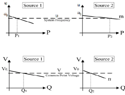
0 are the no load values of angular frequency and voltage respectively as shown in Figure 6. [image:3.595.321.525.56.211.2]Figure 6 Droop characteristic curves
Figure 6 shows the droop characteristic curves for active and reactive power sharing based on the droop coefficients. For sharing the active and reactive power among two inverters, the droop coefficients should be inversely related to their power rating.
2 2 11
S
m
S
m
(10)
2
2 1
1
S
n
S
n
(11)Additionally, droop coefficients should satisfy the following relation. 2 2 1 1
n
m
n
m
(12)Conventionally, droop coefficients are defined as in Equation (13) and (14)
max
P
m
(13)
max
Q
v
n
(14)
where
and
v
are maximum allowable deviations offrequency and voltage while
P
max andQ
max are maximumactive and reactive powers. The reference values are obtained by the droop control. The conventional droop control scheme is shown in Figure 7. From the figure, it is seen that the reference voltage and frequency are generated for an ith inverter. The droop coefficients are calculated using Equation (13) and (14).
Figure 7 Conventional droop control scheme (Qing et al. 2013)
[image:3.595.49.280.84.184.2]Strategy for Flawless Transfer of Islanded and Grid Connected Modes with Modifed Droop Controller
active or reactive power output when the frequency or voltage of the inverters changes from the nominal values. Voltage and frequency reference values are set by the droop controller for the parallel operation of inverter for power sharing and for regulating voltage and frequency.
4.1 Real Power Sharing
In steady state condition, parallel inverters have the same frequency , and so it is obvious that the accuracy of real power sharing with inductive output impedance is maintained accurately as indicated by Li et al. (2009). From Equation (10), the relation is
2
2 1
1
P
m
P
m
(15)Frequency droop coefficients should satisfy Equation (10) & Equation (15) and so real power sharing proportional to its power rating is achieved.
2 2 1 1S
P
S
P
(16)From Equation (6) the relation
2 2 2 2 1 1 1 1
X
V
V
m
X
V
V
m
L
L
(17) If
1
2 andV
1
V
2 exist, then the following relation exists. 2 2 1 1X
m
X
m
(18)If the frequency set points are different for the inverters, then the error in power sharing among parallel unit occurs. Real power deviation due to the deviation of frequency set points
i
by Equation (8) isi i i
m
P
1
(19)When two inverters are connected in parallel with
2 1 2
1
P
P
rP
rP
, the relative power sharing error which may exist due to the measurement of frequency2 1
is 0 0 2 2 1 1 2 2 1 1%
ri i r r r r eP
m
P
P
P
P
P
P
P
P
P
(20) where 0
ri iP
m
is the frequency droop ratio at the rated real
power. If this ratio is smaller, real power sharing error is bigger. For example the frequency boost ratio of 10% and the
frequency set point deviation
0
of 10% which mayoccur for any probable reasons, the real power sharing error is 100%. The accuracy is much reduced.
4.2 Reactive Power Sharing
For real power sharing relation between real power and frequency droop coefficients exist as per Equation (15). Similarly, to achieve reactive power sharing
2
2 1
1
Q
n
Q
n
(21)and
2 2 1 1S
Q
S
Q
(22)the voltage deviation should be zero as of Equation (3.9). Voltage deviation cannot be maintained at zero because of disturbances, errors, system parameter variations and so on. The relation exists for reactive power from Equation (6)
for
V
1
V
2 is,2 2 1 1
X
n
X
n
(23)where n1 and n2 are selected proportional to their output
reactance. The per unit impedance of the inverter is given by
2 L i i i L i i
V
S
X
I
V
X
(24)Equation (24) is equivalent to
2
1
(25)The output impedances of the parallel inverters should be the same for proportional reactive power sharing. Based on this criteria, virtual output impedance method is used for power sharing by Guerrero (2006). If this condition is not satisfied, then the voltage set points are not the same for the inverters and reactive power sharing error occurs.
By Equation (9), reactive power deviation due to variation in voltage set point of the inverter ΔVi is
i i
i
v
n
Q
1
(26)When two inverters are connected in parallel with
2 1 2
1
Q
Q
rQ
rQ
, the relative power sharing error which may exist due to the measurement of voltage2
1
v
v
v
is0 0 2 2 1 1 2 2 1 1
%
v
v
Q
n
v
Q
Q
Q
Q
Q
Q
Q
Q
Q
ri i r r r r e
(27) where 0v
Q
n
i riis the voltage droop ratio at
the rated reactive power. If this ratio is smaller, reactive power sharing error is bigger. For example, frequency boost ratio of 10% and voltage set
point deviation
0
v
v
ofprobable reason, the reactive power sharing error is 100%. The accuracy is much reduced.
If the system is stable for parallel inverters with inductive output, then the following conditions prevail.
2 2 1 1 2 1 1X
m
X
m
C
(28) and
2 2 1 1 2 1 2X
n
X
n
v
v
C
(29)An additional condition of the above equations is that mi and
ni should be proportional to each other. If C1 is satisfied for
real power sharing, the reactive power sharing is also achieved. If C2 is satisfied for reactive power sharing, then
real power sharing is also achieved. However, this is not possible in reality to meet ω1= ω2 or v1=v2 because of
practical difficulties. It is also not possible to maintain ϒ1= ϒ2
due to the difference in the impedances and mismatches in the components. Moreover, the droop coefficients are fixed in conventional droop control. There is a possibility that all the inverters may start operating with a lower value of frequency and magnitude of the voltage which are different from the set point frequency and voltage.
V. LIMITATIONS OF CONVENTIONAL DROOP
CONTROL
There exist a few problems with the existing droop characteristics as listed below.
1.To share the load in proportion, all the parallel connected inverters have to measure the same load voltage and frequency (i.e) line impedances should be the same. 2.Due to fixed droop coefficients, all inverters may start
operating with a new lower frequency and voltage comparatively different from the set point values.
3.The droop coefficients must be smaller for lesser reduction in load voltage. The response is sluggish for smaller droop coefficients which should be chosen bigger for a fast response. So, there is a contradiction in selecting the droop coefficients.
5.1 MODIFIED DROOP CONTROLLER
The conventional droop controller is modified to share the load equally among the inverters when the above mentioned uncertainties occur. The voltage and frequency drop due to droop control as in Equation (8) and (9). From the droop equations, it is clear that
i i i
i
m
p
0 (30)i i i
i
v
v
n
q
v
0 (31) Change in voltage is integrated and is implemented in the loop proposed by Marwali et al. ( 2004), Li et al .(2004) and Marwali et al.(2008)
t ii
v
dt
v
0 (32)
But the controller works only for grid connected mode, and not for islanded mode of operation. Load voltage drops due to
load effect and droops effect. For smaller values of
n
i andi
m
the voltage and frequency drop would be lesser, but the smaller value would slow down the response. For maintainingthe voltage with limited range, the voltage drop
(
v
0
v
L)
has to be fed back through an amplifier gain. Similarly for maintaining frequency within limited range, frequencydifference
(
0
L)
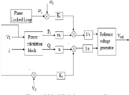
has to be fed back through amplifier gain. Due to this modification load voltage drop and frequency drop are considered along with droop effect, and so the performance gets improved. Proportional load sharing is maintained accurately among inverters even when the voltages and frequencies are not the same. [image:5.595.317.541.213.378.2]The modified droop controller is shown in Figure 8.
Figure 8 Modified droop controller
Under steady state condition, the input of the integrator should be zero. So, the following conditions prevail instead of Equations (8) and (9)
)
(
0 Li i i
P
K
m
(33))
(
01
Q
iK
iv
v
Ln
(34)For constant
K
i value,m
iP
i is always the same which assures equal real power sharing for all the parallel inverters.Similarly,
n
1Q
i is always the same which assures equal reactive power sharing for all the parallel inverters. Real and reactive power is shared accurately without having the samefrequency and voltage i.e
i andv
i . The possibility of deviation in real and reactive power sharing may be due to the measurement of the load voltage and frequency. The possible real and reactive power sharing error is given by the following equations.
i i im
K
P
(35)v
n
K
Q
i i i
(36)From Equation (33) & (34) the following relation exists.
0 0
0
Strategy for Flawless Transfer of Islanded and Grid Connected Modes with Modifed Droop Controller
0 0
0
v
v
K
Q
n
v
v
i i i
L
(38)In the above equation, voltage drop ratio
0
v
K
Q
n
i i
i considers the voltage drop due to load effect
and droop effect. Conventional droop controller by Sao (2005) considers only drop due to droop effect. The strategy in conventional literature compensates drop due to load effect, but not due to droop effect whereas the proposed controller improves voltage regulation by compensating voltage drop due to load effect and droop effect. The droop equation is not decided by the output impedance as given in Equation (7), but by the parameters in voltage drop ratio.
Voltage drop can be reduced if
K
i value is very large because it is proportional to the ratioi i
K
n
, but the sharing
error as per Equation (36) is proportional to the ratio
i i
n
K
.
So, a contradiction exists between voltage drop and power sharing error. Voltage drop and sharing error can be reduced
by properly choosing
K
i value.5.2 Droop Calculation Block
In conventional method, the droop values are fixed and calculated as per Equation (8) and (9). The coefficients depend on the maximum power and do not change if any change in the output power of the inverter exists. If any major variation occurs, these fixed coefficients would make the system unstable. With this proposed method, new droop coefficients are adopted for any major deviation from normal situations that occur. Robustness and reliability increase by using these estimated coefficients. The following equations are used to generate tracking signals for the control loops.
)
(
ˆ
P
iK
i 0 Lm
(39))
(
ˆ
Q
iK
iv
0v
Ln
(40)VI. SIMULATION OF MICROGRID WITH
MODIFIED AND ESTIMATED DROOP CONTROLLER
For verifying the proposed method for sharing active and reactive power among the inverters, a sample microgrid with two sources along with constant and switched loads is considered.
6.1 Simulation of Parallel Inverters
To analyze the performance of the proposed controller two different cases are considered for simulation.
Case 1: Two parallel inverters with the same line
impedance for
K
i value as 2Case 2: Two parallel inverters with the same line
impedance for
K
i value as 26.1 Simulation of Parallel Inverters
To analyze the performance of the proposed controller two different cases are considered for simulation.
Case 1: Two parallel inverters with the same line
impedance for
K
i value as 2Case 2: Two parallel inverters with the same line
impedance for
K
i value as 26.2 Case 1: Two Parallel Inverters with Same Line Impedance
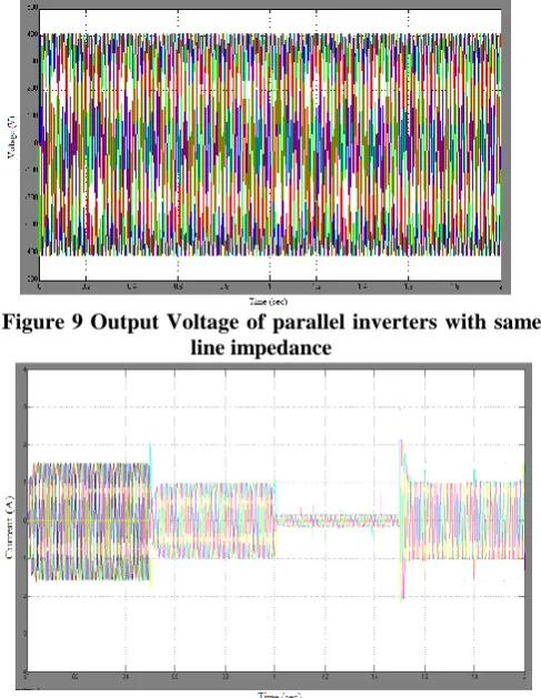
[image:6.595.304.548.312.627.2]The performance of the system is analyzed for the system with same line impedance. Initially, inverter 1 is connected to the load and inverter 2 is connected at 0.5 seconds. The system responds to the change quickly and the inverters get synchronised. Figure 9 shows that the voltage of both the inverter remains the same and the slight deviation is not visible due to the overlapping of two signals. Parallel inverters share equal voltages as well as the equal current which can be seen from Figure 10 . The output current of inverter 2 before 0.5 second is 0A which is then equally shared between two inverters. The load is varied at 1 and then at 1.5 seconds. At all these variations,the response of the system is faster and it stabilises at a quicker rate. Frequency is maintained at nominal value for both the inverters which can be seen from Figure 11.
Figure 9 Output Voltage of parallel inverters with same line impedance
Figure 11 Frequency of parallel inverters with same line impedance
Figure 12 Estimated frequency droop of inverters with same line impedance
Figure 13 Estimated voltage droop of inverters with same line impedance
Figure 14 Real powers of two inverters with same line impedance
Figure 15 Reactive power of two inverters with same line impedance
Curves for estimated frequency droop coefficients of the inverters are shown in Figure 12. The values are automatically estimated after 0.5 seconds for inverter 2 and it remains same for both the inverters. This is the different feature compared with the conventional controller where drrop coefficients are fixed initially. Similarly, plots for voltage droop coefficients for the parallel inverters are shown in Figure 13. The same droop value ensures equal power sharing among parallel inverters . Equal power sharing is shown in Figures 14 and 15.
6.3 Case 2: Two Parallel Inverters with Different Line Impedance
[image:7.595.305.541.52.189.2] [image:7.595.48.290.225.704.2]Strategy for Flawless Transfer of Islanded and Grid Connected Modes with Modifed Droop Controller
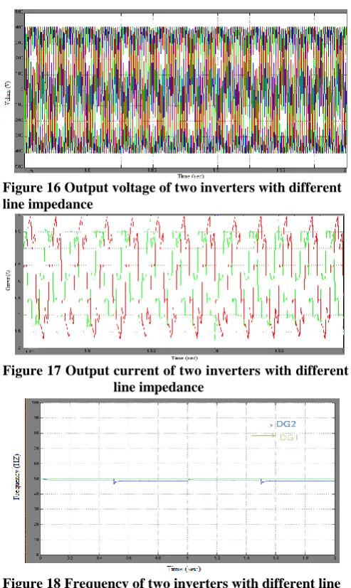
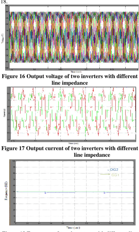
[image:8.595.314.539.52.184.2]Figure 16 Output voltage of two inverters with different line impedance
[image:8.595.308.542.54.363.2]Figure 17 Output current of two inverters with different line impedance
Figure 18 Frequency of two inverters with different line impedance
[image:8.595.308.546.212.372.2]Figure 19 Estimated frequency droop of inverters with different line impedance
Figure 20 Estimated voltage droop of inverters with different line impedance
Figure 21 Real powers of two inverters with different line impedance
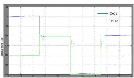
Figure 22 Reactive power of two inverters with different line impedance
Parallel inverters estimate their droop coefficients based on the impedance and power output. This can be seen in Figures 19 and 20. Real and reactive power of the inverters is shown in Figures 21 and 22. Parallel inverters are delivering different values of real and reactive power to the load.
VII. CONCLUSION
In this paper, real and reactive power sharing is improved by incorporating modifications in the conventional droop loop. Droop coefficients are estimated for the operating condition which is different from the conventional method where the coefficients are fixed. Drop due to load effect and droop effect are considered and compensated for improving voltage regulation. The droop equation is not decided by the output impedance, so the power sharing is proper for both same and for different line impedances. Simulation results show that the proposed approach is able to share both real and reactive power among inverters independently according to changes in load demand. The performance of the system is analyzed for the system with same line impedance. Initially, inverter 1 is connected to the load and inverter 2 is connected at 0.5 seconds. The system responds to the change quickly and the inverters get synchronised. Figure 9 shows that the voltage of both the inverter remains the same and the slight deviation is not visible due to the overlapping of two signals. Parallel inverters share equal voltages as well as the equal current which can be seen from Figure 10 . The output current of inverter 2 before 0.5 second is 0A which is then equally shared between two inverters. The load is varied at 1 and then at 1.5 seconds. At all these
[image:8.595.49.286.445.752.2]at a quicker rate. Frequency is maintained at nominal value for both the inverters which can be seen from Figure 11.
[image:9.595.307.543.55.347.2]Figure 9 Output Voltage of parallel inverters with same line impedance
[image:9.595.49.290.67.394.2]Figure 10 Output current of parallel inverters with same line impedance
Figure 11 Frequency of parallel inverters with same line impedance
Figure 12 Estimated frequency droop of inverters with same line impedance
Figure 13 Estimated voltage droop of inverters with same line impedance
[image:9.595.48.291.339.559.2]Figure 14 Real powers of two inverters with same line impedance
Figure 15 Reactive power of two inverters with same line impedance
Curves for estimated frequency droop coefficients of the inverters are shown in Figure 12. The values are automatically estimated after 0.5 seconds for inverter 2 and it remains same for both the inverters. This is the different feature compared with the conventional controller where drrop coefficients are fixed initially. Similarly, plots for voltage droop coefficients for the parallel inverters are shown in Figure 13. The same droop value ensures equal power sharing among parallel inverters . Equal power sharing is shown in Figures 14 and 15.
6.3 Case 2: Two Parallel Inverters with Different Line Impedance
Performance is analyzed for parallel inverters with different line impedances. With conventional droop strategy system will become unstable due to high flow of voltage and current due to the problem of
[image:9.595.307.543.396.533.2] [image:9.595.46.290.596.733.2]Strategy for Flawless Transfer of Islanded and Grid Connected Modes with Modifed Droop Controller
[image:10.595.312.540.46.494.2] [image:10.595.316.536.54.177.2]the same during load variations. Due to the different line impedance output current of the inverters are different. The load shared by the inverters will be different when the impedance is different among the inverters. Both inverters are expected to inject different value of current into the load. Figure 17 shows the injected current values of the inverters. For clear understanding, the current is shown for one phase only. It is visible that the inverter currents are different and the phase angle difference is evident. Even then the inverters are synchronised and system is stable . It is observed that the phase difference is almost 90 degree which does not affect the phase difference between voltages. It is observed from the literature that with conventional droop strategy the phase difference is 180 degree when line impedances are different. If the phase difference is 180 degree, it would create phase difference between voltage which would disturb the synchronisation process. In the proposed droop controller the phase difference between the currents does not exceed 90 degree which assures stability even with different line impedances. Secondly, the frequency of the whole system is maintained at a normal value and it is observed from Figure 18.
Figure 16 Output voltage of two inverters with different line impedance
Figure 17 Output current of two inverters with different line impedance
Figure 18 Frequency of two inverters with different line impedance
Figure 19 Estimated frequency droop of inverters with different line impedance
[image:10.595.46.290.301.708.2]Figure 20 Estimated voltage droop of inverters with different line impedance
Figure 21 Real powers of two inverters with different line impedance
Figure 22 Reactive power of two inverters with different line impedance
[image:10.595.307.545.522.663.2]VIII. CONCLUSION
In this paper, real and reactive power sharing is improved by incorporating modifications in the conventional droop loop. Droop coefficients are estimated for the operating condition which is different from the conventional method where the coefficients are fixed. Drop due to load effect and droop effect are considered and compensated for improving voltage regulation. The droop equation is not decided by the output impedance, so the power sharing is proper for both same and for different line impedances. Simulation results show that the proposed approach is able to share both real and reactive power among inverters independently according to changes in load demand.
REFERENCES
1. Marwali, M, Jung, JW & Keyhani, A 2004, ‘Control of distributed generation systems—Part II: Load sharing control’, IEEE Trans. Power Electron., vol. 19, no. 6, pp. 1551–1561.
2. Soultanis, NL, Papathanasiou, SA and Hatziargyriou ND 2007, ‘A stability algorithm for the dynamic analysis of inverter dominated unbalanced LV microgrids,’ Power Systems, IEEE Transactions on, vol. 22, no. 1, pp. 294-304.
3. Ferre A.J., Green T.C. and Soto-Sanchez (2011) ‘Current control reference calculation issues for the operation of renewable source grid interface VSCs under unbalanced voltage sags’, IEEE Transactions on Power Electronics, Vol. 26, No.12, pp. 3744–3753.
4. Li Y. and Li Y.W. (2011) ‘Power management of inverter interfaced autonomous microgrid based on virtual frequency-voltage frame’, IEEE Transactions on Smart Grid, Vol. 2, No. 1, pp. 30–40
5. Pedro Rodriguez, Alvaro Luna and Remus Teodorescu (2013) ‘A stationary reference frame grid synchronization system for three-phase grid-connected power converters under adverse grid conditions’, IEEE Transactions on Power Electronics, Vol. 27, No. 1.
6. Qing Chang Zhong 2013, ‘Robust droop controller for accurate proportional load sharing among inverters operated in parallel,’ IEEE Transactions on Industrial Electronics, vol. 60, no. 4, pp. 1281-1290. 7. Nayan, N, Pandya, Hemant, I, Joshi, Bhavik, N, Suthar 2014,
‘Identification of Weak Bus and Voltage Stability Enhancement’ International Journal of Innovative Research In Electrical, Electronics, Instrumentation And Control Engineering, vol.2, issue. 4, pp.1374-1377.
8. Indresh G S, Sunil kumar B S, Rajesh M, Prashanth T & Shobha Shankar (2014).Enhancement of Power System Security by TCSC under Single Line Outages., in Proceedings Hawaii International Conference System Science vol. 2.
9. A Sheela, S Vijayachitra, S Revathi, “H-infinity controller for frequency and voltage regulation in grid-connected and islanded microgrid” IEEJ Transactions on Electrical and Electronic Engineering, Vol 10, issue 5, pp 503-511, September. 2015 10. Alepuz, S, Monge, S & Rodriguez, J 2009, ‘Control strategies based on
symmetrical components for grid-connected converters under voltage dips’, IEEE Transactions on power system, vol. 56, no. 6, pp.2162–2173.
11. Ali, HI, Mohd Noor, SB, Marhaban, MH & Bashi, SM 2010, ‘Design of H-inf controller with tuning of weights using particle swarm optimization method’, IAENG International Journal of Computer Science, vol.38, no.2, pp. 1-10.
12. Alvaro Giustol 1996, ‘H∞ and Hz robust design techniques for static prefilters’, Proceedings of the 35th Conference on Decision and Control Kobs, pp. 237-242.
13. Amin Hajizadeh, Masoud Aliakbar Golkar & Ali Feliachi, 2010, ‘Voltage Control and Active Power Management of Hybrid Fuel-Cell/Energy-Storage Power Conversion System Under Unbalanced Voltage Sag Conditions’, IEEE Transactions on Energy Conversion, vol. 25, no. 4, pp.1195-1208.
14. Barklund, E, Nagaraju Pogaku, Milan Prodanovic, C, Hernandez-Aramburo & Tim C Green 2008, ‘IEEE Energy Management in Autonomous Microgrid Using Stability-Constrained Droop Control of Inverters’, IEEE Transactions on Power Electronics, vol. 23, no. 5, pp. 3049–3056.
15. Bellmunt, O, Ferre, A, Sumper, A & Jane, J 2008, ‘Ride-through control of a doubly fed induction generator under unbalanced voltage
sags’, IEEE Transactions on Energy Conversion., vol. 23, no. 4, pp. 1036–1045.
16. Bin Li Xiaohe & Tian Zhiqian Bo 2011, ‘A Grid-Connection Control Scheme Of Pv System With Fluctuant Reactive Load’ 21st International Conference on Electricity Distribution, pp-1-4. 17. Bin Zhang, Danwei Wang, Keliang Zhou & Yigang Wang 2008,
‘Linear Phase Lead Compensation Repetitive Control of a CVCF PWM Inverter’, IEEE Transactions on Industrial Electronics, vol.55, issue. 4, pp 1595-1602.
18. Bobrowska-rafal, M, Rafał, K, Abad, G & Jasiński, M 2009, ‘Control of PWM rectifier under grid voltage dips’, Bulletin of the polish Academy of Sciences Technical Sciences vol. 57, no. 4, pp.337-343. 19. Bollen, MH 1999, ‘Understanding Power Quality Problems’, Voltage
Sags and Interruptions, New York: IEEE Press, pp 950-960. 20. Bragard, M, Martin Bejvl & De Doncker, W 2013, ‘The balance of
renewable sources and user demands in grids Power electronics for modular battery energy storage systems’, IEEE Transactions on Power Electronics, vol. 25, no. 12, pp. 3049–3056.
21. Castilla, M & Vicuna, LG 2010, ‘Grid fault control scheme for three-phase photovoltaic inverters with adjustable power quality characteristics’, IEEE Transactions on Power Electronics, Vol 25, no.12, pp.2930-2940
AUTHORS PROFILE