i
ABSTRACT
ii
ABSTRAK
iii
DEDICATION
iv
ACKNOWLEDGEMENT
In the Name of Allah, the Most Beneficent, the Most Merciful
Assalamu’alaikum and Greetings
First and foremost, I would like to express all my deepest gratitude and thanks to Allah S.W.T, the only God Almighty, the Most Gracious and Most Merciful for all His blessing and His guidance that I, Iqmal Aizad bin Abdullah, to have been able to successfully complete this Final Year Project (FYP) and prepare this final year report.
Moreover, I would like to thank to my supervisor Dr. Muhammad Arfauz bin A. Rahman for spending his time and giving me advices guidance, support, encouragement and knowledge of this research. I would like to thank him for giving me the chance to learn a new field of studies. The ups and down of the search shall be an experience I will cherished my whole life.
v
TABLE OF CONTENTS
ABSTRACT i
ABSTRAK ii
DEDICATION iii
ACKNOWLEDGEMENT iv
TABLE OF CONTENTS v
LIST OF TABLES viii
LIST OF FIGURES ix
ABBREVIATION xiv
CHAPTER 1 1
1.1 Background 1
1.2 Problem Statement 2
1.3 Objectives 3
1.4 Scope 3
1.5 Organization 4
CHAPTER 2 5
2.1 Data acquisition system 5
2.1.1 Analogue DAQ 6
2.1.2 Digital DAQ 7
2.1.3 DAQ Models 8
2.2 Ergonomic Parameter 19 2.2.1 Posture and Movement 20 2.2.2 Environmental Factor 22 2.2.3 Information and Operation 28 2.2.4 Work organization, jobs and task 29 2.3 Instruments for Measurement of Ergonomic Environment
Parameter 30
2.3.1 Temperature sensors 30 2.3.2 Sound Sensors (Microphones) 34
2.3.3 Light Sensor 35
2.3.4 Humidity sensor 38
2.4 GUI software 42
2.4.1 LabVIEW 42
2.4.2 MATLAB® 43
2.4.3 Altia DeepScreen 45
vi
2.5 Concluding remarks 46
CHAPTER 3 48
3.1 Project plan 48
3.1.1 Flow chart 48
3.1.2 Gantt Chart 49
3.2 GUI Software used (LabVIEW) 50
3.2.1 Templates 51
3.2.2 Real-Time Sample Projects (DAQmx) 53 3.2.3 Graphical User Interface (GUI) 54 3.3 Environment ergonomic parameters 54
3.4 DAQ system 55
3.4.1 NI cDAQ-9184 55
3.4.2 Module 58
3.5 Sensors 63
3.5.1 Light sensor module (SN-LIGHT-MOD) 64 3.5.2 Temperature sensor (LM 35) 64
3.6 Conceptual design 65
3.6.1 Humidity conceptual data acquisition system 66 3.6.2 Light conceptual data acquisition system 67 3.6.3 Sound conceptual data acquisition system 67 3.6.4 Temperature conceptual data acquisition system 68
3.7 Development stage 69
3.7.1 GUI Functions 69
3.7.2 GUI Parameters Front Panels 81 3.7.3 GUI Parameters Coding 87 3.8 Manual acquisition device 110 3.8.1 TSI Airflow Instruments Multi-function Anemometer TA465 110 3.8.2 ExTech Foot Candle Lux Light Meter 407026 Heavy Duty 111 3.8 Validation procedure 111
3.8.1 Temperature 112
3.8.2 Light 113
CHAPTER 4 115
4.1 DAQ platform 115
4.2 GUI response. 116
vii
4.2.12Reading exceeds limit 141 4.2.13User placed lower limit higher than upper limit 142
4.3 Validation result 145
4.3.1 Temperature validation result 145 4.3.2 Light validation result 153
4.4 Discussion: 164
4.4.1 Temperature validation analysis 164 4.4.2 Light validation analysis 167
CHAPTER 5 170
Conclusion 170
Future work 170
REFERENCES 171
viii
LIST OF TABLES
2.1 Recommended light level 24
3.1 Gantt chart of project 49
3.2 LabVIEW system requirements 50
4.1 LabTemp1 reading using DAQ platform 146
4.2 LabTemp1 reading using TSI Airflow Instruments 146
4.3 LabTemp2 reading using DAQ platform 147
4.4 LabTemp2 reading using TSI Airflow Airflow Instruments 147
4.5 LabTemp3 reading using DAQ platform 148
4.6 LabTemp3 reading using TSI Airflow Instruments 148
4.7 LabLight1 reading using DAQ platform 154
4.8 LabLight1 reading using ExTech light meter 155
4.9 LabLight2 reading using DAQ platform 156
4.10 LabLight2 reading using ExTech light meter 157
4.11 LabLight3 reading using DAQ platform 158
4.12 LabLight3 reading using ExTech light meter 159
4.13 DAQ platform LabTemp reading 166
4.14 TSI airflow instrument LabTemp reading 166
4.15 Average variation between LabTemp 166
4.16 DAQ platform LabLight reading 168
4.17 ExTech LabLight reading 169
ix
LIST OF FIGURES
2.1 DAQ platforms 9
2.2 National Instrument 9
2.3 Low-Channel-Count, Single DAQ Devices 10
2.4 Medium-Channel-Count, Modular DAQ Systems 10
2.5 High-Channel-Count, Modular DAQ Systems 11
2.6 DATAQ Instruments 13
2.7 Texas Instruments 15
2.8 Wire Gas Sensor Solution 19
2.9 Jobs consists of tasks that, in turn, consists of actions 29
2.10 Temperature Sensors 30
2.11 Sound sensors 34
2.12 Light Sensors 36
2.13 Light dependent resistor cross section 37
2.14 Photo-junction device 37
2.15 Humidity sensors 39
2.16 Resistive-polymer sensor 41
2.17 Simple capacitive sensor 41
2.18 LabVIEW 43
2.19 MATLAB 44
2.20 Altia DeepScreen 45
2.21 EICASLAB 46
3.1 Project flow chart 48
3.2 Top view of chassis 56
3.3 Front view of chassis 56
3.4 Side view of chassis 57
3.5 NI 9203 module 58
3.6 Input circuitry on the NI9203 59
3.7 Connecting Single-Ended Current Signals to the NI 9203 60
3.8 NI 9205 Module 60
x
3.10 Connecting a Device to the NI 9205 Using Differential Connections 62
3.11 Connecting a Device to the NI 9205 Using RSE Connections 62
3.12 Connecting a Device to the NI 9205 Using NRSE Connections 63
3.13 Light sensor module 64
3.14 LM 35 65
3.15 DAQ system conceptual design 66
3.16 Humidity DAQ 66
3.17 Light DAQ 67
3.18 Sound DAQ 68
3.19 Temperature DAQ 69
3.20 Initialization state front panel 70
3.21 Initialization state block diagram 70
3.22 Home ideal state front panel 71
3.23 Home ideal state codes 71
3.24 Framework for User ideal code 72
3.25 Framework for run code 73
3.26 Quit initialization function 73
3.27 Quit homepage 74
3.28 Quit parameter interface 74
3.29 Saving application 76
3.30 Tab control function 77
3.31 Tab change 78
3.32 DAQmx function 78
3.33 Alarm VI 79
3.34 Alarm VI front panel and block diagram 79
3.35 Warning function 80
3.36 Category function 81
3.37 GUI of Humidity 82
3.38 GUI of Temperature 83
3.39 GUI of Light 84
3.40 GUI of Sound 85
3.41 GUI of Combined 86
3.42 Flat sequence 87
xi
3.44 Humidity phase I block diagram 89
3.45 Humidity phase II block diagram 90
3.46 Humidity phase III block diagram 91
3.47 Block diagram of Temperature interface 92
3.48 Temperature phase I block diagram 93
3.49 Temperature phase II block diagram 94
3.50 Temperature phase III block diagram 95
3.51 Block diagram of Light GUI interface 96
3.52 Light phase I block diagram 97
3.53 Light phase II block diagram 98
3.54 Light phase III block diagram .. 99
3.55 Block diagram of Sound GUI interface 100
3.56 Sound phase I block diagram 101
3.57 Sound phase II block diagram 102
3.58 Sound phase III block diagram 103
3.59 Block diagram of Combined GUI interface 104
3.60 Combined phase I block diagram 105
3.61 Combined phase II block diagram 107
3.62 Combined phase III block diagram 109
3.63 TSI TA465 110
3.64 ExTech Light Meter 111
3.65 Temperature validation test set up 112
3.66 Light validation test set up 113
4.1 Finalize DAQ platform 116
4.2 User press Start during initialization state 117
4.3 Block diagram flow during initialization 118
4.4 User choose HUMIDITY 119
4.5 Block diagram flow when HUMIDITY is chosen 120
4.6 User choose TEMPERATURE 121
4.7 Block diagram flow when TEMPERATURE is chosen 122
4.8 User choose LIGHT 123
4.9 Block diagram flow when LIGHT is chosen 124
4.10 User choose SOUND 125
xii
4.12 User choose COMBINED 127
4.13 Block diagram flow when COMBINED is chosen 128
4.14 User choose physical channel 129
4.15 Setting input terminal 130
4.16 Setting frequency of reading 130
4.17 Setting upper and lower boundary 131
4.18 Pressing file icon 131
4.19 Setting save function 132
4.20 User starting acquisition 132
4.21 Acquisition block diagram flow 134
4.22 User stop acquisition 136
4.23 User return to homepageduring ideal 137
4.24 User quit in initialization 138
4.25 Code for quitting during initialization 138
4.26 User quit from homepage 138
4.27 Code for quitting from homepage 139
4.28 User presses quit during acquisition 139
4.29 User quit from a parameter interface during ideal 140
4.30 User quit from a parameter interface during ideal 140
4.31 Code for quitting from parameter interface (Ideal state) 141
4.32 Warning for above upper limit 141
4.33 Warning for below than lower boundary 142
4.34 Warning case 142
4.35 Lower limit is set higher than upper limit during acquisition 143
4.36 Limit error issued during acquisition 143
4.37 Lower limit higher than upper limit during ideal 143
4.38 Limit error issued after ideal case 145
4.39 LabTemp1 chart using DAQ platform 149
4.40 LabTemp1 chart using TSI Airflow Instruments 149
4.41 LabTemp2 temperature reading using DAQ platform 150
4.42 LabTemp2 temperature reading using TSI Airflow Instrument 150
4.43 LabTemp3 temperature reading using DAQ platform 151
4.44 LabTemp3 temperature chart using TSI Airflow Instruments 151
xiii
4.46 LabTemp2 comparison chart 152
4.47 LabTemp3 comparison chart 152
4.48 LabLight1 chart using DAQ platform 160
4.49 LabLight1 chart using ExTech light meter 160
4.50 LabLight2 chart using DAQ platform 161
4.51 LabLight2 chart using ExTech light meter 161
4.52 LabLight3 chart using DAQ platform 162
4.53 LabLight3 chart using ExTech light meter 162
4.54 LabLight1 comparison chart 163
4.55 LabLight2 comparison chart 163
xiv
ABBREVIATION
HF&E - Human Factor and Ergonomics DAQ - Data Acquisition
COM - Common terminal COG - Centre of gravity VDU - Visual display unit %RH - Relative humidity
1
CHAPTER 1
INTRODUCTION
This chapter gives the introduction on the subject of the project. A general overview on the field of study for this project.
1.1 Background
Human factor and ergonomic, (HF&E), is a practice of making the user, equipment and the environment suit one another. HF&E is also known as comfort design, user-friendly design and functional design. It is common not to place a degree HF&E to a design unless there is a need to do so. Sometimes good design are unnoticed (with an exception for a brilliant design) but a poor design could be spot much easily. According to the International Ergonomics Association is technically defined as the scientific discipline concerned with the interactions between humans and other elements. Further definition defines it as a profession that applies theory, principles, data and methods to design in order to optimize human wellbeing and overall system performance.
2 should be done to how you should seat on a chair. Ergonomics studies involve taking data on factors that would allow a person to stay focus in his job in his current working condition. For example working in the office involves taking into account the type of chair, the sitting position, the distance from the computer and the footrest. Generally speaking it takes account the details big or small that would contribute to the sustainable or increasing efficiency of the human working condition. Among the details that contribute to ergonomic condition, the environment have an impact on human capabilities to work. This study for environment ergonomic is important as the environment as a whole have to be altered or manipulated to fit the needs for efficient condition.
Hence this is where the job of attaining information on the environment is crucial. By using a data acquisition system, DAQ, the real world physical condition could be convert into digital numerical value where it could be manipulated. Usually DAQ convert analogue value into digital analogue for processing. It is a process of measuring an electrical or physical phenomenon such as voltage, temperature, sound or humidity with a computer. It has 3 basic component, which are the sensors to detect physical condition, DAQ measurement hardware, and a computer with a programmable hardware. With the help of PC-based DAQ system, processing power, productivity, display and connectivity capabilities could be used to provide a more flexible, powerful and cost-effective measurement solution.
Obtaining the necessary data for the system could be an inconvenience sometimes as the reading have to be manually keyed into the system. This project is proposed to help make the task of obtaining the relevant data easier through automatic acquisition. The project will use NI CompactDAQ as the data acquisition platform.
1.2 Problem Statement
3 ergonomic information. Apart from that the acquisition requires several devices and user have to be present during the acquisition. Manual extraction is not only tedious but also a time consuming process. People are unable to notice the ergonomic level of their workplace when no monitoring system is present. An automated data acquisition platform that uses a PC-based DAQ can provide the solution.
1.3 Objectives
The objectives of the project are as follows:
i. To identify the available ergonomic parameters.
ii. To analyse the available ergonomic acquisition approach technology in the market.
iii. To design and develop the ergonomic acquisition platform.
1.4 Scope
In order to achieve the objectives, there are still certain limitation to just how wide the breadth of the project goes. The scope of the project are:
i. While there are various factors in ergonomics, the project focus on the environment factors specifically on light and temperature in the laboratory. ii. The data acquisition (DAQ) equipment used in the project is the NI
CompactDAQ™-9184, National Instrument.
iii. This project will utilize the LabVIEW software for acquiring the parameters. iv. The setup of this project is on a laboratory scale where it will be implemented
4 1.5 Organization
This report is organized as follows:
Chapter 1 discuss on background of ergonomics, the problem statement, objectives, scope and how the project is organize to give an overhead view of the project.
Chapter 2 discusses on research that have been done regarding the topic of ergonomics, methods of conduct, implementation of the concept and equipment used for collecting information on ergonomics parameter.
Chapter 3 describes the methodology including the overall flow chart and also Gantt chart for the project plan.
Chapter 4 will find details on acquired performance test, system development from designing phase up till implementation of DAQ platform on a laboratory set up environment.
5
CHAPTER 2
LITERATURE REVIEW
Chapter 2 shows the literature that is used as the reference for the project. The information are based on the relevancy with the proposed project. The literature review is taken from journal, article, books and online resources.
2.1 Data acquisition system
Development on science and technology has showed the embedded computer technology is an important part of computer field is related with people’s lives and has received major interest in the area of research and as well as application. Data acquisition (DAQ) is a type of instrumentation system or devices united by some form of regular interaction of an interdependence (A course in electrical and electronic measurements and instrumentation, 2001). This group of devices operate in unison according to a form of control. Data acquisition, which is an important branch of computer applications, is an integrated application of technology, based on sensors, signal measurement, data processing end embedded systems (Wang Jiannong, 2011).
Data acquisition has become widely used in the field of industrial automation and also scientific research where the actual performance of data acquisition system becomes the key that decides the performance of production line and the quality of the output. It is vital to understand the significance of data acquisition system and the characteristics of the device itself by testing the actual environment.
6 software, the signal is compared by hand, repeat experiment obtains the effective accuracy of data acquisition.
Today, signal are able to be detected by using various devices. For example, analogue signal are used in communication and even medical. With rapid development in the circuitry industry, complex circuits are now able to be operated with greater accuracy and ease by using digital conversion DAQ at a relatively lower cost. The system in DAQ consist of:
1. Analogue system. This system handles information in analogue form. Analogue signals are a continuous function. Example is a plot of voltage against time.
2. Digital system. A digital quantity consist of discrete or discontinuous pulses where the time relationship contains information about the magnitude and nature of the measured entity.
2.1.1 Analogue DAQ
There are two ways that data acquisition measures and record analogue signals:
Signals which originate from measurement of electrical quantities. This can be in the form of a.c. or d.c. voltages, frequency or resistance.
Signals from the use of transducers.
The analogue signal would undergo a signal conditioning where amplification would take place and a multiplexer is used which acts as a switching device to allow the input to be sampled. An analogue data-acquisition system consist some or all of the following elements:
7
Signal Conditioning Equipment. This includes any equipment that assists in transforming the transducers output to the required magnitude or form necessary to the DAQ. This includes signal amplifying, refining or selecting certain position of the signals.
Multiplexer. The term multiplexing is used in the process of sharing a single channel with more than one output. A multiplexer accepts multiple analogue inputs and connects them sequentially to one measuring input. This is done either by sharing time or frequency of the transmission between the individual quantities.
Callibrating Equipment.
Integrating Equipment. It is often that the integral of summation of a quantity is to be determined. There is a method involving the use of an analogue integrating circuit. Another method is the utilization emf from the conditioning equipment placed to a saturable core reactor in the resonant circuit of an oscillator.
Visual Display Devices. Visual aid is required for continuous monitoring of the input signals.
Analog Recorders.
Analog Computers. Transducers and sensors data can be recorded and also reduced to desired form.
High Speed Cameras and TV Equipment. For cases where the test operators are unable to view the equipment being tested, closed circuit TV are used and sometimes the application of high speed cameras for a complete visual record.
2.1.2 Digital DAQ
Digital Data acquisition system include some or all of the following components:
Transducers. This allows the conversion of physical quantity into an electrical signal.
Signal Conditioning Equipment.
8
Signal Converter.
Analogue to Digital Converter (A/D Converter). An A/D converter converts an analogue voltage to its equivalent digital form. This allows the output to be display or recorded in a digital recorder. The data could be fed to digital computer for data reduction and processing. ADC operation are defined wit a few parameters
N Bits - Defines how many binary bits represent the analog digital output.
Vmin - The minimum analog voltage to be converted to digital output.
Vmax - The maximum analog voltage to be converted to digital output.
It essentially divides the analog range (Vmin to Vmax) into 2𝑁 levels. Each level has a corresponding digital value from 0 to2𝑁−1. The ADC takes input voltage, finds the closest discrete analog level and assigns the corresponding digital count to the ADC output.
Auxiliary Equipment. This includes devices use for system programming functions and digital data of signals.
Digital Recorders.
Digital Printers. This device allows for high quality of hard copy of records and reduce minimize the labour cost by interfacing the printer with an electronic instrumentation system.
2.1.3 DAQ Models
9
Figure 2.1 : DAQ platforms
2.1.3.1 National Instrument (NI)
Figure 2.2 : National Instrument (National Instrument, 2014)
(a) Introduction
National instruments have been founded in 1976. Just last year in 2013, its annual revenue was $1.17B. The company operates in nearly 50 countries. The cooperation between engineers and scientist has allowed NI to come up with various products to market and overcome difficult technological roadblocks.
(b) DAQ characteristics
[image:23.595.117.450.382.465.2]10 ASEAN country such as Malaysia, Thailand, Philippines and Vietnam. National Instrument provides software such as NI LabVIEW and modular cost-effective hardware. Below are samples of NI DAQ devices:
[image:24.595.241.373.194.293.2] Low-Channel-Count, Single DAQ Devices
Figure 2.3: Low-Channel-Count, Single DAQ Devices
(National Instrument, 2014)
The buses include USB, Ethernet, PCI, PCI Express, and WiFi.
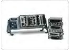
Medium-Channel-Count, Modular DAQ Systems
Includes in portable form and includes direct sensor connectivity. Available on USB, Ethernet, and WiFi as well as with stand-alone options.
Figure 2.4 : Medium-Channel-Count, Modular DAQ Systems
[image:24.595.225.359.474.571.2]