DSP Embedded Smart Surveillance Sensor with
Robust SWAD-based Tracker
Gaetano Di Caterina1, Iain Hunter2, and John J. Soraghan1
1 Department of Electronic and Electrical Engineering, University of Strathclyde,
204 George Street, Glasgow, G1 1XW, UK
2
Texas Instruments Limited, 800 Pavilion Drive, Northampton, NN4 7YL, UK
Abstract. Smart video analytics algorithms can be embedded within surveillance sensors for fast in-camera processing. This paper presents a DSP embedded video analytics system for object and people tracking, us-ing a PTZ camera. The trackus-ing algorithm is based on adaptive template matching and it employs a novel Sum of Weighted Absolute Differences. The video analytics is implemented on the DSP board DM6437 EVM and it automatically controls the PTZ camera, to keep the target central to the field of view. The EVM is connected to the network and the track-ing algorithm can be remotely activated, so that the PTZ enhanced with the DSP embedded video analytics becomes a smart surveillance sensor. The system runs in real-time and simulation results demonstrate that the described SWAD outperforms other template matching measures in terms of efficiency and accuracy.
1
Introduction
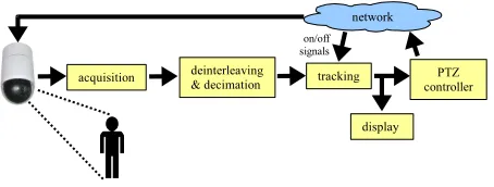
The video analytics algorithm on the EVM automatically controls the PTZ cam-era to follow the target and keep it central to the field of view, when it moves towards the frame boundaries. The EVM is connected to the network and, dif-ferently from the system in [3], the tracker can be activated and deactivated from remote, through on/off TCP-based messages. The contribution of this pa-per is therefore threefold: first, a real-time DSP embedded implementation of the SWAD-based tracker described in [4] is presented; second, extended perfor-mance evaluation of the SWAD-based tracker compared with SAD, NCC and MS is provided; third, the smart surveillance system in [3] is improved with re-mote activation, faster processing and better tracking performance, to create, in conjunction with the PTZ camera, an embedded smart surveillance sensor.
The remainder of the paper is organized as follows. Section 2 reviews related work in the field of tracking algorithms and embedded surveillance applications. An overview of the DSP embedded system described in this paper is given in section 3, while section 4 describes the video analytics implemented on the DSP, including tracking algorithm and camera controller. Section 5 provides a quanti-tative performance evaluation of the system, while section 6 concludes the paper.
2
Related work
The implementation of image processing algorithms on embedded platforms poses challenges due to hardware limitations and time constraints. However, a number of implementation techniques were introduced to overcome these is-sues [5–7]. Previous work using static cameras [8–10] describe the implementation of smart surveillance sensors, for example for object detection and tracking.
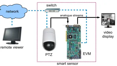
Fig. 1. Overview of the DSP embedded system, with the EVM and PTZ coupled together to form a smart surveillance sensor.
for the work presented in this paper would be to implement the same video analytics algorithm on an FPGA, for further performance evaluation.
The migration from a computer-based implementation of a tracking algo-rithm, like those described in [17], to a DSP embedded one is not straightfor-ward. In such a context, the hardware available plays a fundamental part in the choice of the actual algorithm to implement. In this work, a PTZ camera is used, so that algorithms which rely strictly on the position of the target in the previous frames do not represent an ideal choice. For example, the Mean-Shift tracker (MS) [18] requires target overlapping in consecutive frames, within the so-called basin of attraction. However, this condition cannot be guaranteed with a moving camera.
On the other hand, DSP boards have limited resources, such as memory, bandwidth and word-length for number representation, so that not every track-ing algorithm is suitable for an embedded implementation. In the proposed sys-tem, the hardware available is a DM6437 EVM equipped with a single core fixed-point DSP, that can perform integer operations on groups of 4–8 bytes in parallel. Therefore, on such DSP, algorithms working with floating point num-bers would not take advantage of the architecture of the processor. Also in this case, the MS is not an ideal choice, as it heavily relies on floating point oper-ations. Instead, two algorithms that can exploit such architecture are Normal-ized Cross-Correlation (NCC) and Sum of Absolute Differences (SAD) template matching [19]. As we will shown in section 5, the SAD algorithm gives better per-formance than NCC in terms of efficiency, since additions are performed much faster than multiplications. However, SAD fails in many cases when occlusion or noise pixels exist. In this paper the new Sum of Weighted Absolute Differences proposed in [4] is implemented, as it can deal with partial occlusions, offering better tracking performance than SAD, as demonstrated in section 5.
3
DSP embedded system
Fig. 2.Block diagram of the video analytics system.
a Spectrum Digital DM6437 Evaluation Module (EVM) equipped with a Texas Instruments TMS320DM6437 fixed-point DSP; and an ACTi IP Speed Dome CAM-6510, which is a pan-tilt-zoom (PTZ) camera with 360◦ panning range, 180◦tilting range and a maximum angular speed of 400◦per second. A composite analogue video signal is also available as output from the PTZ and is fed into the EVM’s video-in port. Both PTZ and EVM are connected to a local area network (LAN) through their Ethernet interfaces, so that they can communicate with each other via TCP/IP. For display purposes only, the EVM’s video-out port is connected to a video display.
The system software is implemented in C and runs in real-time at more than 30 frames per second on the EVM. The PTZ camera hosts a proprietary web server and hence no software has been developed for it. Commands for the PTZ are encoded in HTTP requests to the camera web server. The video analytics algorithm on the EVM controls the PTZ by issuing such HTTP-based commands over the network. The EVM also runs a simple TCP server, so that remote on/off signals can be sent to the EVM, to activate the tracking algorithm.
When in stand-by mode, the system does not track any target and the PTZ can be moved freely. When the algorithm is activated, it starts tracking what is in the middle of the field of view at that exact moment. It is straightforward to integrate the proposed DSP embedded smart sensor with other event-based surveillance systems: for example an external smart system [20] can detect an event, compute the 3D position of the target, control the PTZ to point on the target, and then activate the SWAD-based tracking algorithm on the EVM, to follow the designated target.
4
Embedded video analytics
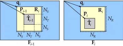
Fig. 3.Layout of the current frameFishowing the best matchTˆi, the region of interest
Riand their positions withinFi.
4.1 Acquisition, deinterleaving and decimation
The composite analogue video output from the PTZ is fed into the EVM’s video-in port. This video stream is digitized into 8-bit interleaved YCbCr 4:2:2 frames of 576×1440 pixels, with CbYCrY packed format and video resolution of 576×720 pixels, by the video decoder present on the EVM board. A deinter-leaving operation separates individual YCbCr 4:2:2 frames into luminance (Y), blue (Cb) and red (Cr) chrominance components, of which the tracking algo-rithm requires only Y to perform its task. The luminance component is then downsampled by a factor of 2 both vertically and horizontally, achieving a frame size of 288×360 pixels.
For speed optimization on the EVM, deinterleaving and decimation are per-formed at the same time, by simply extracting only the required samples from the 4:2:2 YCbCr frames. IfJiis theithinterleaved YCbCr 4:2:2 frame of 576×1440
pixels, the corresponding decimated luminance componentFiof 288×360 pixels
is computed as:
Fi(x, y) =Ji(2x,4y+ 1) :x∈[0, H−1], y∈[0, W−1] (1)
whereH = 288 andW = 360 are height and width ofFi.
4.2 Adaptive template matching target tracking
The tracking algorithm implemented on the DM6437 EVM is the adaptive tem-plate matching with minimization of a Sum of Weighted Absolute Differences (SWAD) described in [4]. The target model is represented by a templateTi of
NT ×NT pixels. As illustrated in Fig. 3, in the current frame Fi a region of
interest Ri of NR×NR pixels, with NR = NT + 2NS, is selected around the
target position pi−1 in the previous frame Fi−1. The best matchTˆi in Fi for
the target templateTi is found within the region of interestRi, by minimizing
the SWAD coefficientψ(x, y) computed as:
ψ(x, y) =
NT−1
X
m=0
NT−1
X
n=0
with pixel difference∆(x, y, m, n):
∆(x, y, m, n) =|Ri(x+m, y+n)−Ti(m, n)| (3)
The kernelKin (2) is:
K(x, y) =
255· g(x, y)
g(bµc,bµc)
(4)
where x, y∈ [0, NT −1] and g(x, y) is a 2-dimensional Gaussian function with
meanµ= (NT−1)/2 and standard deviationσ=NT/5, defined as:
g(x, y) = exp
−(x−µ)
2
2σ2 −
(y−µ)2 2σ2
(5)
Such kernel is used to assign high weights to central pixels and low weights to peripheral ones, as these pixels might belong to background or even occluding objects. In our DSP-based implementation, the values in K and the absolute differences in the SWAD metric are integers in the range [0,255]. The kernel val-ues are computed offline once and stored in a look-up table. Using 8-bit integers allows us to optimally exploit the fixed-point architecture of the DM6437 DSP. To take into account possible rescaling, rotation and target changes in gen-eral, the target template is updated using an infinite impulse response filter approach. Therefore the new target templateTi+1 is computed as:
Ti+1= (1−α)Ti+αTˆi (6)
where α∈[0,1] is a blending factor. In our implementation it is α= 0.5. The positionpiinFiof the best matchTirepresent the position of the target in the
current frame. This information is passed to the PTZ control block, to decide whether to pan/tilt the camera.
4.3 PTZ controller
The commands for the PTZ camera are hexadecimal sequences of 6 bytes in-cluded as parameters within standard HTTP requests, sent from the algorithm on the EVM to the web server running on the PTZ camera. The tracking algo-rithm establishes a TCP connection and sends the appropriate commands to the PTZ when the target approaches the frame boundaries. This situation is handled as follows. The current frameFi is divided into horizontal and vertical regions,
as shown in Fig. 4: left (HL), centre (HC) and horizontal-right (HR); vertical-top (VT), vertical-centre (VC) and vertical-bottom (VB). For a given best match Tˆi in Fi, the PTZ pans to the left ifTˆi overlaps the
HL region, or to the right if Tˆi overlaps HR; otherwise the camera does not
move horizontally. Similarly, the PTZ tilts up if Tˆi overlaps VT, or tilts down
if Tˆi overlaps VB; otherwise the camera does not move vertically. This simple
Fig. 4.Horizontal and vertical regions in the frameFi.
Fig. 5.Four images from the tracking algorithm running on the EVM.
4.4 Video display
The high resolution digital video output from the PTZ can be accessed over the network. For display purposes only, an analogue video signal is available from the EVM’s video-out port. This signal contains the interleaved 4:2:2 YCbCr versionSi of the frameFi, with the values of the chrominance pixels set to 127.
The interleaved frame Si is therefore a single plane matrix, with size equal to
H ×2W = 288×720 pixels. The interleaving process is performed similarly to the deinterleaving process described in section 4.1. For every new incoming frame Fi, only the pixels of Si corresponding to the luminance component are
modified and set equal toFi, while all the other pixels remains set to 127, as:
Si(x, y) =
Fi(x, m), y= 2m+ 1
127, otherwise (7)
where x ∈ [0, H −1], y ∈ [0,2W −1] and m ∈ [0, W −1]. Four frames from the video analytics algorithm running on the EVM are shown in Fig. 5. For display purpose, the best match Tˆi, the region of interestRi and the vertical
and horizontal regions described in section 4.3 are all highlighted on the display. Note that the current templateTi is shown on the top-left corner of each video
frame.
5
System performance evaluation
In this section, a quantitative evaluation of the embedded system is given.
5.1 Accuracy and precision
[image:7.612.136.477.215.286.2]SWAD-Table 1.Mean valueµand standard deviationσof erroriin pixels, and percentage
λof frames with lowest error, for each tracker.
SAD NCC MS SWAD
µ σ λ µ σ λ µ σ λ µ σ λ
Dudek 4.25 2.54 7% 4.29 2.36 24% – – – 3.67 2.13 34% PETS2006 30.99 22.56 0% 34.13 24.21 0% 14.19 4.44 7% 10.91 4.14 93% PETS2007 6.67 6.22 15% 9.93 9.24 11% 7.34 1.35 7% 3.89 1.50 53% PETS2009 4.27 3.25 37% 27.38 47.80 7% 81.95 97.72 0% 2.26 1.42 48%
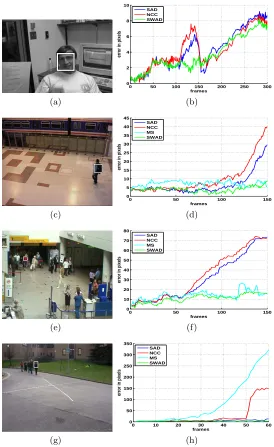
based adaptive template matching tracker, as shown in Fig. 6. Four publicly available test sequences have been used: Dudek face sequence [21], S1-T1-C/3 from PETS2006 dataset [22], S06 2/1 from PETS2007 dataset [23], and S3-multi-12.43/8 from PETS2009 dataset [24]. As the Dudek sequence is in grey scale, the MS has not been applied to it. The ground truth for the Dudek sequence is already available, while the three PETS sequences have been manually labelled. For each frameFi, an erroriis computed in terms of Euclidean distance between
the ground truth and the target position returned by the trackers. The accuracy in pixels of a tracker is therefore obtained as mean valueµ of the errori over
a sequence, while the precision is computed as the standard deviationσ. With
λwe define the percentage of frames in a sequence in which a given tracker has
the lowest error compared with the other trackers. In the left column of Fig. 6 the first frames with initial target positions for each sequence are shown, while in the right column graphs of the erroriare illustrated. Numerical values ofµ,
σ and λ are reported in Table 1. It can be seen that in general the error for
SWAD is significantly lower, with better accuracy and precision, i.e. the lowest mean error µ and standard deviation σ. Moreover the SWAD-based tracker
has also the lowest error for most of the frames, i.e. highestλ.
5.2 Execution time
After manual profiling and code optimization, the total running time of the DSP embedded SWAD-based adaptive template matching target tracking algorithm described in section 4 is of 15 ms per frame, giving a processing frame rate comfortably higher than the real-time requirement of 25−30 fps. The SWAD matching block in (2) and (3) withNT = 32 andNS = 50 takes 7 ms.
Optimiza-tion for the SWAD matching is achieved by exploiting the C code “intrinsics”, which are specific functions for the C6000 architecture of the DM6437 DSP [25]. Each C-level intrinsic function is mapped to a single assembly instruction and it executes additions, multiplications and absolute subtractions on groups of four 8-bit integers. For example, the intrinsic function MEM4 reads 4 pixel values from memory; SUBABS4 computes the absolute difference between two groups of 4 pixels; and DOTPU4 computes the dot product between two vectors of 4 pixels. This approach reduces the number of operations for each row of pixels in the templateTiby a factor of 4. A plain implementation of the SWAD matching
[image:8.612.133.483.145.212.2](a)
0 50 100 150 200 250 300 0 2 4 6 8 10
error in pixels
frames SAD NCC SWAD (b) (c)
0 50 100 150
0 5 10 15 20 25 30 35 40 45
error in pixels
frames SAD NCC MS SWAD (d) (e)
0 50 100 150
0 10 20 30 40 50 60 70 80
error in pixels
frames SAD NCC MS SWAD (f) (g)
0 10 20 30 40 50 60
0 50 100 150 200 250 300 350
error in pixels
[image:9.612.171.445.113.560.2]frames SAD NCC MS SWAD (h)
Fig. 6.Accuracy and precision test. (a-b) Dudek face sequence; (c-d) PETS2006; (e-f) PETS2007; (g-h) PETS2009. (a-c-e-g) Initialization frames; (b-d-f-h) error distance from ground truth in pixels.
An optimized version of the SAD matching using intrinsic functions takes 5 ms. Nonetheless, even though SWAD is slightly slower than SAD, its better tracking performance reported in section 5.1 entirely justifies its usage over con-ventional SAD. Concerning an implementation of NCC on the DM6437, it can be said that extra care must be taken to simulate floating point operations, as for example square root, in integer arithmetic. It takes about 9 ms just to com-pute the mean values of the template Ti and of each NT ×NT subregion in
the ROI Ri. Thus it is clear that the execution of a complete implementation
of NCC matching on the DM6437 DSP would definitely take longer than 7 ms, and therefore NCC would be slower than SWAD.
6
Conclusion
In this paper we have presented a DSP embedded smart surveillance tracking sensor, using a PTZ camera to follow a target and always keep it central to the field of view. The system runs in real-time and it is implemented on the fixed-point single core DSP DM6437 Evaluation Module. The adaptive template matching tracking algorithm employs a robust Sum of Weighted Absolute Dif-ferences (SWAD) to maintain high accuracy under noise and partial occlusion when conventional SAD fails. The system can be used as a working framework to develop new real-time matching techniques for tracking and video analytics. The system can also be easily integrated with other surveillance systems, to create a collaborative network of smart surveillance sensors.
Currently the speed of the active camera is fixed and therefore the system might fail in case of (very) fast moving targets. It is planned to set the panning and tilting angular speed of the camera proportional to the speed of the target. In such a way, the system should be able to follow very fast moving targets. Also, a zooming capability is going to be incorporated in the smart sensor. Finally, a strategy for handling severe and complete occlusion will be also added.
References
1. Valera, A., Velastin, S.A.: Intelligent distributed surveillance systems: a review. IEE Proc. - Vision, Image and Signal Processing152(2) (2005) 192–204
2. Dee, H., Velastin, S.A.: How close are we to solving the problem of automated visual surveillance? A review of real-world surveillance, scientific progress and evaluative mechanisms. Machine Vision and Applications19(5-6) (2008) 329–343
3. Di Caterina, G., Hunter, I., Soraghan, J.: An embedded smart surveillance system for target tracking using a PTZ camera. In: European DSP Education and Research Conference. (2010) 165–169
4. Di Caterina, G., Soraghan, J.J.: Adaptive template matching algorithm based on swad for robust target tracking. IET Electronics Letters48(5) (2012) 261–262 5. Hunter, I.: Overview of embedded DSP design. In: European Signal Processing
Conference. (2009) 475–479
7. Kisacanin, B., Nikolic, Z.: Algorithmic and software techniques for embedded vision on programmable processors. Signal Processing: Image Communication, Elsevier
25(5) (2010) 352–362
8. Wang, Y., Velipasalar, S., Casares, M.: Cooperative object tracking and composite event detection with wireless embedded smart cameras. IEEE Trans. on Image Processing19(10) (2010) 2614–2633
9. Magno, M., Tombari, F., Brunelli, D., Di Stefano, L., Benini, L.: Multimodal abandoned/removed object detection for low power video surveillance systems. In: IEEE Int. Conf. on Advanced Video and Signal Based Surveillance. (2009) 188–193 10. Arth, C., Bischof, H.: Real-time object recognition using local features on a DSP-based embedded system. Journal of Real-Time Image Processing, Springer-Verlag
3(4) (2008) 233–253
11. Yang, C.S., Chen, R.H., Lee, C.Y., Lin, S.J.: PTZ camera based position tracking in IP surveillance system. In: Int. Conf. on Sensing Technology. (2008) 142–146 12. Kumar, P., Dick, A., Sheng, T.S.: Real time target tracking with pan tilt zoom
camera. In: Digital Image Computing: Techniques and Applications. (2009) 492– 497
13. Chang, F., Zhang, G., Wang, X., Chen, Z.: PTZ camera target tracking in large complex scenes. In: World Congress on Intelligent Control and Automation. (2010) 2914–2918
14. Micheloni, C., Rinner, B., Foresti, G.L.: Video analysis in pan-tilt-zoom camera networks. IEEE Signal Processing Magazine27(5) (2010) 78–90
15. McErlean, M.: An FPGA implementation of hierarchical motion estimation for embedded object tracking. In: IEEE Int. Symposium on Signal Processing and Information Technology. (2006) 242–247
16. McErlean, M.: Hierarchical motion estimation for embedded object tracking. In: IEEE Int. Symposium on Signal Processing and Information Technology. (2006) 797–802
17. Yilmaz, A., Javed, O., Shah, M.: Object tracking: a survey. ACM Computing Surveys38(4) (2006) 1–45
18. Comaniciu, D., Ramesh, V., Meer, P.: Kernel-based object tracking. IEEE Trans. on Pattern Analysis and Machine Intelligence25(5) (2003) 564–577
19. Tombari, F., Di Stefano, L., Mattoccia, S.: A robust measure for visual correspon-dence. In: Int. Conf. on Image Analysis and Processing. (2007) 376–381
20. Manap, N.A., Di Caterina, G., Ibrahim, M.M., Soraghan, J.J.: Co-operative surveillance cameras for high quality face acquisition in a real-time door moni-toring system. In: European Workshop on Visual Information Processing. (2011) 99–104
21. Visual Tracking Benchmark: Dudek face sequence.
http://www.cs.toronto.edu/vis/projects/adaptiveAppearance.html (2003) 22. PETS 2006: Benchmark Data.
http://www.cvg.rdg.ac.uk/PETS2006/data.html (2006) 23. PETS 2007: Benchmark Data.
http://www.cvg.rdg.ac.uk/PETS2007/data.html (2007) 24. PETS 2009: Benchmark Data.
http://www.cvg.rdg.ac.uk/PETS2009/a.html (2009)