Pseudospark Experiments: Cherenkov Interaction and
Electron Beam Post-Acceleration
H. Yin, A. W. Cross, W. He, A. D. R. Phelps, and K. Ronald
Abstract—Pseudospark (PS) discharge experiments to generate high-brightness electron beams have been carried out at the Strathclyde University, Glasgow, U.K. The PS-sourced electron beam has two phases, an initial 22-kV, 50-A hollow-cathode phase (HCP) beam of brightness 109 10 Am 2 rad 2 followed by a 200-V, 200-A conductive phase (CP) beam of brightness 1011 12 Am 2 rad 2. The initial HCP beam from an eight-gap PS discharge was applied for the first time in a Cherenkov interaction between the electron beam and theTM01 mode of a 60-cm long alumina-lined waveguide. A gain of 29 3 dB was measured and an output power of 2 0.2 kW in the frequency range 25.5–28.6 GHz. Another experiment was focused on the study of the propagation and post-acceleration of the CP beam from a three-gap PS discharge chamber. The beam was successfully accelerated from about 200 V to more than 40 kV.
Index Terms—Cherenkov interaction, electron beams, post-ac-celeration, pseudospark (PS).
I. INTRODUCTION
P
SEUDOSPARK (PS) discharge [1]–[3] experiments to generate a low-temperature plasma for use as a copious source of electrons have been carried out at the University of Strathclyde, Glasgow, U.K. [4], [5]. The plasma can be regarded as a low-work function surface that facilitates elec-tron extraction. Elecelec-tron beam pulses of duration of tens of nanoseconds, current density ( 10 Am ), brightness of up to 10 Am rad and emittance of tens of millimeters mrad were measured from a PS discharge. This beam has a higher combined current density and brightness compared to electron beams formed from any other known type of electron source. A PS-based, high-intensity, high-brightness electron beam source was applied for the first time in a free-electron maser device at the University of Strathclyde [6], [7].Another experiment was focused on the study of the propaga-tion and post accelerapropaga-tion of the beam from a three-gap PS dis-charge chamber. A beam from the PS disdis-charge was transported in a plasma induced ion background and simultaneously accel-erated by an accelerating potential. This makes it possible to provide a higher energy electron beam with lower energy spread for future application in a high-power free-electron maser. This paper will present some results from both the Cherenkov inter-action and post-acceleration experiments.
II. EXPERIMENTALSETUP
A. Cherenkov Maser Experimental Setup
A schematic outline of the PS-based Cherenkov maser amplifier is shown in Fig. 1. The main components of the ex-periment are the PS-based electron beam source, the magnetic field for beam transport, the Cherenkov interaction region, electrical/beam diagnostics, and the microwave launching/diag-nostic system. A more detailed description of the experimental setup can be found in [7].
In the maser system, the presence of the dielectric in the wave-guide reduces the phase velocity of the electromagnetic waves, allowing a resonant interaction to occur between a TM or HE waveguide mode and the rectilinear electron beam. Coherence of the generated radiation arises due to bunching of electrons in phase with respect to the electromagnetic wave. For values of the beam and waveguide parameters relevant to this experi-ment, the force exerted on the electrons by the waveguide mode was dominated by the resonant space-charge force, so the maser operated in a Raman-type regime, with strongest amplification of the waveguide mode expected when it was resonant with the slow space-charge wave of the beam, i.e., when the angular fre-quency and the axial wavenumber of the waveguide mode satisfy
(1)
where is the axial electron velocity,
is the relativistic factor, is
the plasma frequency, is the electron density, , is the relative velocity, is the total electron velocity, is the speed of light, and and are the electronic charge and rest mass, respectively. and must also, of course, satisfy the character-istic equation for a dielectric-lined cylindrical waveguide, which for a mode is as in [7]. From the space-charge mode of the electron beam and the and waveguide modes for this Cherenkov maser experiment, a resonant interaction of the beam mode would be expected to occur around 21 GHz with the mode and 55 GHz with the mode.
Fig. 1. Cherenkov maser experimental configuration.
(using a compact Rogowski coil upstream from the interac-tion region) and the transported beam current (using another compact Rogowski coil downstream from the interaction region). The microwave pulse duration and temporal profile from the PS-based Cherenkov maser amplifier were obtained by monitoring the output of a rectifying crystal detector with an oscilloscope. The basic microwave measurement system, screened in a metal box, was composed of Ka-band (26.5–40 GHz) or W-band (75–100 GHz) components starting with a small microwave receiving horn followed by a directional coupler, attenuators, waveguide, and crystal detectors. Two methods were used to identify the frequency range of the Cherenkov radiation. One technique used a series of in-wave-guide cutoff filters, and the other used an interferometer. From the first method, both the frequency and the energy distribution were obtained.
The radiation mode pattern (i.e., the field distribution and the power distribution) measurements of the Cherenkov maser were conducted by scanning a radially polarized detector in a circular path centred on the aperture of the output horn while repeatedly pulsing the maser device. The field distribution and the power distribution are dependent on the distance from the launching antenna to the detector, which can be divided into three identi-fiable regions without sharp boundaries including the reactive near-field region (Rayleigh field), the radiating near-field gion (Fresnel region), and the far-field region (Fraunhofer re-gion). The power distribution measurements were conducted in the far-field region. For the Cherenkov maser, the diameter of the output horn was 6 cm and the dominant frequency of the source was about 25.5 GHz ( cm) and the far field conditions required that the launching and receiving antenna should be separated by larger than 61 cm. Therefore, the de-tector was placed at 1 m away from the launching horn. A refer-ence detector system was detached and placed at a fixed position through the entire mode scanning experiment to compensate for random fluctuations in the maser output.
B. Electron Beam Post-Acceleration Experimental Setup
A schematic outline of the experimental setup for the study of the propagation and the post-acceleration of the PS-sourced beam is shown in Fig. 2. The electron beam was extracted from a three-gap PS discharge chamber. The discharge chamber con-sisted of a planar anode, a planar cathode with a cylindrical hollow cavity, two intermediate electrodes of 3.25-mm thick-ness and three Perspex insulators of 3.25-mm thickthick-ness. The cylindrical hollow cathode cavity was made of stainless steel having outer and inner diameters of 63 and 50 mm, respectively,
Fig. 2. Schematic diagram for the post-acceleration experiment of the PS electron beam.
and length 50 mm, in which a trigger electrode made of coaxial cable was inserted. Both the anode and cathode had an on-axis hole of 3-mm diameter. The post-acceleration gap was located 30 mm away from the anode of the PS discharge chamber. The single Perspex disc of inner diameter 5 mm, outer diameter 300 mm, and 26-mm thickness was used for acceleration gap insu-lation. It was made with a recess to achieve a 5-mm acceleration gap separation.
A Rogowski coil was located 120 mm downstream of the post-acceleration gap to measure the beam current. The gas inlet was located 30 mm away from the Rogowski coil and was con-trolled by a very fine mechanical needle valve. The background vacuum requirements were obtained using a two stage pumping system in the form of a rotary pump and an oil-diffusion pump. Air was used throughout the experiments. The pressure was measured by a Baratron type vacuum gauge together with a dis-play meter.
[image:2.612.318.542.193.269.2]Fig. 3. Typical waveforms of PS discharge voltage, the beam current, and the microwave pulse.
III. EXPERIMENTALRESULTS
A. Cherenkov Maser Experimental Results
The operation of the whole maser system is described as follows. The maser system was originally evacuated down to 2–3 mtorr at the discharge chamber and 0.01 mtorr at the pumping port. The pumping port was connected at the end of the output horn using a glass “T-piece” chamber. Argon gas was fed into the system from the anode side at a very slow rate of 1 mtorr/s through a very fine controlled needle valve until a desired gas pressure was reached and balanced by adjustment of the needle valve. The high voltage applied across the PS chamber was increased slowly until breakdown occurred. To achieve a self-pinched, high-current electron beam, it was essential to match the applied discharge voltage and chamber gas pressure so that the discharge operated in the PS regime. Our experiments showed an empirical relation of , where is the breakdown voltage of the PS discharge in kilovolts, and and are the pressure in torr and the cathode–anode separation in centimeters, respectively. The self-pinched electron beam was extracted from the anode hole of the eight-gap PS discharge chamber just before breakdown occurred and then guided along the beam tube to the Cherenkov interaction region, where the beam interacted with the modes of the dielectric lined wave-guide, and the resonant wave was amplified to a few kilowatts from a low power level of a few watts. The microwave radiation generated in the interaction region was guided a further 60 cm in a cylindrical vacuum waveguide before being launched into free space by the conical output horn. The microwave radiation was then diagnosed by a screened and calibrated microwave diagnostic system situated in the far field of the antenna.
Microwave radiation was detected successfully from the PS-based dielectric Cherenkov maser amplifier. The temporal profile of the microwave output radiation from the maser is shown in the lower part of Fig. 3, while time correlated with the electron-beam current and voltage profiles. It was found exper-imentally that significant microwave radiation was generated only when the dielectric was present in the interaction space, although if there was no dielectric in the cylindrical waveguide, then a very small background microwave output was detected.
Fig. 4. Results with cutoff filters for the emissions from the PS and the Cherenkov maser output signal.
This demonstrated in conjunction with the observation that the microwave output signal was independent of the guide magnetic field over the range 0.13–0.26 T, that the radiation from the experiment was due to the Cherenkov interaction mechanism. In addition, two components of the microwave pulse were observed corresponding to the two energy components of the electron beam during the PS discharge breakdown. Another interesting result was the discovery that the small background signal was always present even without the guide B-field or dielectric lining in the waveguide. These results demonstrated that the microwave radiation grew from the background seed signal, which seemed to be from the PS discharge itself [9], [10].
[image:3.612.67.262.60.215.2]Fig. 5. Normalized Cherenkov maser output signals with various high-pass filters and the time-correlated accelerating potential.
Fig. 6. Far-field mode pattern scan of the radial componentE compared with calculations and bench calibration.
microwave output had typically two frequency components: one was between 25.5 and 28.6 GHz and the other between 28.6 and 41.8 GHz. By normalizing the Cherenkov maser output signals in Fig. 4, an averaged, normalized microwave output was obtained for each cut-off filter configuration and is shown in Fig. 5. By comparing the time evolution of the beam voltage with the averaged microwave output spectrum, it was found that the low-frequency microwave signal corresponded to a 70- to 80-keV beam energy from the hollow-cathode discharge regime and the higher frequency microwave signal to the lower energy beam from the conductive phase of the PS discharge. This increase in frequency with decreasing beam energy is consistent with a Cherenkov interaction mechanism when the phase velocity of the wave mode is larger than its
group velocity , as in our case.
To verify the mode of operation as , the far-field output radiation pattern from the conical output horn, which had an aperture diameter of 60 mm, was measured. The output an-tenna pattern associated with the azimuthal E-field component was measured to be independent of the presence of the dielec-tric and close to zero, confirming the operation of a TM mode. Fig. 6 shows the measured pattern associated with the radial E-field component of the radiation with a relative error of 4% and a systematic error in the radial angle measurement of 2 . The measured pattern was in good agreement with the results from bench experiments in which a 27-GHz microwave signal was launched using the same horn. Fraunhofer diffraction theory predicts a maximum at 7.5 , which is in close agreement with both the Cherenkov maser experiment and bench measure-ments.
In order to measure the absolute power of the microwave pulse from the Cherenkov maser, the microwave energy received by a 15-dB gain rectangular receiving horn with
TABLE I
PROPAGATION OF THEPS BEAMTHROUGH ACOLLIMATOR
an effective area of 3.5 cm (for the microwave frequency of 25.5 GHz) was fed to a well-calibrated crystal detector. The power density at a range of 1 m and at the maximum of the antenna pattern was measured to be 1.6 0.2 Wcm . Therefore, the maximum total power from the Cherenkov maser was calculated to be 2.0 0.2 kW (without considering any losses within the detecting system) by integrating the measured normalized mode pattern. After similar treatment to the background microwave seed signal from the PS itself without maser amplification, the background microwave seed signal was found to be 2.7 W in the frequency range between 25.5–28.6 GHz. This corresponded to a gain of 29 3 dB.
The observed frequency was found to be 20% higher than that predicted by the resonance condition for 70- to 80-keV beam energy. This discrepancy is probably due to charging of the di-electric liner [11]. A relative spectral energy distribution was obtained and approximately 65% of the radiation was found to lie in the 25- to 28.6-GHz frequency band.
B. Post-Acceleration Experiments
[image:4.612.66.267.206.326.2]Fig. 7. Configuration of the field-free collimator for the brightness measurement on the PS e-beam source.
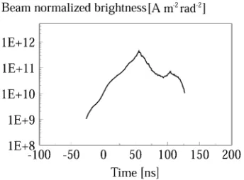
Fig. 8. Measured beam brightness from a three-gap PS discharge.
A magnetic-field free-collimator technique enabled a beam brightness of up to 10 Am rad to be measured from a three-gap PS discharge. The principle of this method is de-scribed in Fig. 7. A cylindrical collimator of radius and length in a magnetic field-free condition is installed concentrically with the electron beam. The beam electrons move divergently in straight lines and the electrons with larger transverse velocity are collimated if is carefully selected such that
(2)
where is the maximum transverse angle of the electrons. The four-dimensional (4-D) trace space area of the collimated electron beam can be calculated as
(3)
where . Therefore, the
bright-ness of the collimated electron beam is given by
(4)
Here, is the relative velocity, the total electron velocity, and the speed of light.
is the relativistic factor. The setup of the beam brightness measurement on the PS experiment is also illustrated in Fig. 2. The brightness can be measured by measuring the beam current and the corresponding voltage which deter-mine the values of and , while and in our experiment were 60 and 1.75 mm, respectively. Fig. 8 shows a measured time-resolved normalized brightness of the electron beam from the three-gap PS. At a discharge voltage of 20 kV, the measured normalized brightness of the CP beam was found to be in the order of 10 Am rad .
[image:5.612.78.250.164.291.2]In the post-acceleration experiment a 30-mm-long collimator of 3.5-mm internal diameter was used after the anode of the PS
Fig. 9. Typical record of the time-correlated PS discharge voltage, beam current, and the acceleration voltage pulse.
Fig. 10. Calculated output power ofTM andTM modes as a function of
z.
discharge chamber and the acceleration unit was located imme-diately after the collimator to achieve a gas pressure gradient and to optimize beam current. The acceleration unit was driven by a 40 kV, 125-ns voltage pulse produced by a cable Blumlein. The beam acceleration experiments showed that careful adjustment of the trigger system could ensure successful synchronization between the beam propagation and the application of the accel-eration voltage. A 40-kV, 100-A electron beam pulse was mea-sured at a distance of 120 mm from the acceleration gap without a magnetic guiding field, as shown in Fig. 9. However, in Fig. 9, some beam loading effect is evident where it can be seen that as the beam current increases the post acceleration voltage de-creases and the flat top of the voltage signal becomes shorter. During the experiments, the beam loading effect was mitigated by reducing the internal impedance of the cable pulser from 50 to 14 . It is possible to further reduce the beam loading ef-fect by continuing to decrease the internal impedance of the cable Blumlein or by using an alternative lower impedance pulse forming line.
IV. SIMULATIONS
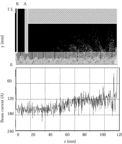
[image:5.612.325.526.220.351.2]Fig. 11. Simulated beam profile and current variation during propagation across the acceleration gap and further along the beam channel with an ion background of density 6210 cm (K–cathode; A–anode; z–beam channel axis; vertical dense lines–plasma zone; and cloud–electrons). Beam parameters: 200 V and 200 A. Acceleration voltage: 40 kV and 125 ns. Acceleration gap: 5 mm.
length for the and modes when the beam energy is 75 keV and current is 10 A. Only these two modes lie within the frequency range of the radiation emitted by the PS discharge. The microwave power at was assumed to be 3 W for both modes. The electron beam was assumed to be a perfectly collimated solid beam, with an axial velocity spread
of 3%, and a radius of 1.5 mm. It should be stressed that there exists a large difference in the lateral and longitudinal energy spread. The lateral energy spread is large while the longitudinal energy spread is very small. It can be seen from Fig. 11 that the mode at 21 GHz is amplified strongly, attaining a power of 3.4 kW at cm, whereas the power in the mode at 55 GHz remains around its initial level. These simulations support the interpretation of the experimental results as microwave amplification via a Cherenkov interaction between the high-quality electron beam and the mode of the dielectric-lined waveguide.
Beam propagation across the acceleration gap and further along the beam channel was simulated using the electromag-netic particle-in-cell code MAGIC. This is a finite-difference, time-domain code for simulating plasma processes and those processes, which involve interactions between space charge and electromagnetic fields. The code is based on Maxwell’s equa-tions, the Lorentz force equation, and the continuity equation. Beginning from a specified initial state, the code simulates a physical process as it evolves in time. The full set of Maxwell’s time-dependent equations is solved to obtain the electromag-netic fields. Similarly, the complete Lorentz force equation is solved to obtain relativistic particle trajectories, and the
conti-nuity equation is solved to provide current and charge densities for Maxwell’s equations. The simulations show that a 200-V, 200-A beam in a PS CP phase will propagate across a 40-kV post-acceleration gap of 5-mm separation in a ion background of certain densities. About 10% and 70% of the beam would propa-gate across the gap when the ion densities are 1 10 cm and 6 10 cm , respectively. Fig. 11 shows a simulated beam profile and current variation during its propagation across the acceleration gap in an ion background of density 6 10 cm . It can be seen that for an initial 200-A beam propagating across the acceleration gap and further along the drift tube, a 130-A beam can be obtained at a distance 120 mm away from the ac-celeration gap. In the experiment, a 100 A beam was measured at a distance about 120 mm away from the acceleration gap. The simulation also shows that with ion background, the shapes of both the cathode and anode of the acceleration gap have little effect on beam propagation.
V. DISCUSSION ANDCONCLUSION
We have presented measurements of coherent electromag-netic radiation generation in a free-electron maser using an elec-tron beam from a PS discharge. The microwave radiation was generated by Cherenkov amplification of the broadband emis-sion from the PS discharge. A background signal level of around 100 W was measured in the frequency range 20–50 GHz with a percentage of 2.7 0.6 % in the frequency range 25.5–28.6 GHz, when the dielectric lining was removed from the maser. The frequency of the microwave output after the Cherenkov maser interaction was measured to be mainly around 25.5 GHz and the dominating mode was identified as being . The duration of the microwave pulse was approximately 80 ns, with a peak power of around 2 0.2 kW. The gain of this amplifier was measured as 29 3 dB. The microwave output was found to be insensitive to the magnitude of the applied magnetic field, which was varied from 0.13 to 0.26 T. The observed frequency, 25.5 GHz, was found to be slightly higher than that predicted by the resonance condition for the above beam parameters and the cold alumina-lined waveguide (21 GHz). This discrepancy could be explained as the effect of either the charging of the di-electric liner or the beam loading effect on the transverse struc-ture of the TM waveguide mode. Therefore, the two microwave pulses, that came from the two parts of the beam originating in the PS, had different frequencies and power amplifications in the Cherenkov interaction. Both the simulation and experiment show that the first microwave pulse of frequency of 25.5–28.6 GHz was amplified in the Cherenkov interaction with a gain of 29 3 dB.
The future aims of this experiment are to improve the performance of the PS discharge with respect to microwave power, pulse repetition frequency, triggering accuracy while operating at high pulse-repetition frequencies, further reduction of the beam loading effect in the post acceleration unit and investigation of the transportation of this novel electron beam in the low-pressure gas-filled interaction region. It is clear that much higher output powers can be obtained from the Cherenkov maser amplifier by using an input signal rather than using the microwave output of the PS discharge. The ultimate goal of the research is to produce electron beam pulses, which offer very favorable comparison of their brightness with the very brightest available photocathode electron sources and have higher current densities, but at a small fraction of the cost of these systems. This work could potentially lead to a whole series of novel microwave sources and amplifiers employing a PS-based high-density high-brightness electron beam.
ACKNOWLEDGMENT
The authors would like to thank the high-power RF Faraday partnership for the provision of the MAGIC code and L. Ludeking of Mission Research Corporation for his helpful instruction in the use of MAGIC.
REFERENCES
[1] J. Christiansen and C. Schultheiss, “Production of high current particle beams by low pressure spark discharge,”Z. Phys., vol. A290, pp. 35–39, 1979.
[2] M. A. Gunderson and G. Schaefer, “Physics and applications of pseu-dosparks,” inNATO ASI, ser. B. New York: Plenum, 1990.
[3] K. Frank and J. Christiansen, “The fundamentals of the pseudospark and its applications,”IEEE Trans. Plasma Sci., vol. 17, pp. 748–753, Oct. 1989.
[4] H. Yin, W. He, A. W. Cross, A. D. R. Phelps, and K. Ronald, “Single-gap pseudospark discharge experiments,”J. Appl. Phys., vol. 90, pp. 3212–3218, Oct. 2001.
[5] H. Yin, A. D. R. Phelps, W. He, G. R. M. Robb, K. Ronald, P. Aitken, B. W. J. McNeil, A. W. Cross, and C. G. Whyte, “A pseudospark cathode Cherenkov maser: Theory and experiment,”Nucl. Instrum. Meth. Phys. Res. A, vol. 407, pp. 175–180, 1998.
[6] H. Yin, W. He, G.R.M. Robb, A.D.R. Phelps, K. Ronald, and A. W. Cross, “Coherent microwave generation from a pseudospark cathode Cherenkov maser,”Phys. Rev. Spec. Topics—Accelerat. Beams, vol. 2, pp. 1–5, 1999.
[7] H. Yin, G. R. M. Robb, W. He, A. D. R. Phelps, A. W. Cross, and K. Ronald, “Pseudospark-based electron beam and Cherenkov maser ex-periments,”Phys. Plasmas, vol. 7, pp. 5195–5204, Dec. 2000. [8] H. Yin, A. W. Cross, A. D. R. Phelps, D. Zhu, W. He, and K. Ronald,
“Propagation and post-acceleration of a pseudospark-sourced electron beam,”J. Appl. Phys., vol. 91, pp. 5419–5422, Apr. 2002.
[9] R. Liou, H. Figueroa, A. H. McCurdy, G. Kirkman-Amemiya, R. J. Temkin, H. Fetterman, and M. A. Gundersen, “Emission of microwave and millimeter wavelength radiation during hollow cathode discharge operation of the back lighted thyratron,”Appl. Phys. Lett., vol. 61, p. 2779, 1992.
[10] K. Ramaswamy, W. W. Destler, and J. Rodgers, “Microwave generation in a high voltage triggered pseudospark discharge experiment,”J. Appl. Phys., vol. 83, pp. 3514–3520, 1998.
[11] E. Garate, R. Cook, P. Heim, R. Layman, and J. E. Walsh, “Cherenkov maser operation at lower-mm wavelengths,”J. Appl. Phys., vol. 58, p. 627, 1985.
[12] W. Peter, E. Garate, W. Main, and A. Fisher, “High-gainX-band dielec-tric Cherenkov maser,”Phys. Rev. Lett., vol. 65, pp. 2989–2992, 1990. [13] H. P. Freund, “Nonlinear analysis of high-power Cherenkov masers,”
Phys. Rev. Lett., vol. 65, pp. 2993–2996, 1990.
Huabi Yin received the B.Eng. degree from Huazhong University of Science and Technology, Wuhan, China, in 1983, the M.Sc. degree from the Graduate School of the China Academy of Engineering Physics, Chengdu, in 1988, and the Ph.D. degree in physics from the Department of Physics, University of Strathclyde, Glasgow, U.K., in 1998.
She is currently a Research Fellow with the Physics Department, University of Strathclyde. Her research interests include the area of pulsed-power technology, pseudospark discharges, intense electron beam production, and microwave sources based on beam-wave instabilities.
Adrian W. Crossreceived the B.Sc. degree (with honors) in physics and the Ph.D. degree from the University of Strathclyde, Glasgow, U.K., in 1989 and 1993, respectively.
He joined the Atoms, Beams, and Plasmas Group, Strathclyde University, in 1993 as a Research Fellow then as a Lecturer in 2000. He is currently a Senior Lecturer with the Department of Physics, Strathclyde University. He has been involved in various aspects of research on gyrotrons, cyclotron autoresonance masers, free electron lasers, superradiant sources, and plasma applications. More recently, he has primarily been concerned with research on radiation sources for use in accelerators and pseudospark physics.
Wenlong Hereceived the B.Sc. degree in physics in 1983 from Suchow University, Gangsu, China, the M.Sc. degree in accelerator physics from the China Academy of Engineering Physics, Chengdu, in 1988, and the Ph.D. degree in relativistic electron beams and masers from the Department of Physics, Univer-sity of Strathclyde, Glasgow, U.K., in 1995.
He is currently a Senior Research Fellow with the Physics Department, University of Strathclyde. His main research interests include relativistic electron beams, CARMs, FELs, and gyro-TWTs.
Alan D. R. Phelpswas born in 1944 in the U.K. He received the B.A. degree (with honors) in physics and the M.A. degree from Cambridge University, Cam-bridge, U.K., in 1966 and 1970, respectively, and the D.Phil. degree for plasma research from Oxford Uni-versity, Oxford, U.K. in 1976.
He founded a research group at Strathclyde Uni-versity, Glasgow, U.K., in 1978, and became a full Professor in 1993. He was the Head of the Physics Department, Strathclyde University, from 1998 to 2001. His research interests include high-power free-electron radiation sources and plasmas.
Dr. Phelps is a Fellow of the Institute of Physics and of the Royal Society of Edinburgh.
Kelvin Ronaldwas born in Glasgow, Scotland, U.K. He received the B.Sc. degree (with honors) in physics and the Ph.D. degree in physics from the University of Strathclyde, Glasgow, in 1992 and 1997, respec-tively.