FPGA Implementation of a Memory-Efficient
Hough Parameter Space for the Detection of Lines
David Northcote*, Louise H. Crockett, Paul Murray
Department of Electronic and Electrical Engineering, University of Strathclyde, Glasgow, Scotland, UK *[email protected]
Abstract—The Line Hough Transform (LHT) is a robust and accurate line detection algorithm, useful for applications such as lane detection in Advanced Driver Assistance Systems. For real time implementation, the LHT is demanding in terms of computation and memory, and hence Field Programmable Gate Arrays (FPGAs) are often deployed. However, many small FPGAs are incapable of implementing the LHT due to the large memory requirement of the Hough Parameter Space (HPS). This paper presents a memory efficient architecture of the LHT named the Angular Regions - Line Hough Transform (AR-LHT). We present a suitable FPGA implementation of the AR-LHT and provide a performance and resource analysis after targeting a Xilinx xc7z010-1 device. Results demonstrate that, for an image of 1024x1024 pixels, approximately 48% less memory is used than the Standard LHT. The FPGA architecture is capable of processing a single image in 9.03ms (110 frames per second).
I. INTRODUCTION
The Line Hough Transform (LHT) is a well known tech-nique for detecting lines within digital images [1], [2]. The LHT algorithm achieves line detection, using a simple local peak detection process in an associated Hough Parameter Space (HPS). In the HPS, the parameters of edge pixels, i.e. points in an image with sharp intensity changes, are treated as ‘votes’, and accumulated. The effect is to create local peaks in the HPS, corresponding to lines in the image. The algorithm is robust and can operate successfully in noisy images and when there are gaps in a line.
Major drawbacks of the LHT are its demands in terms of computation and memory. Previous work provides optimisa-tions to reduce its complexity in software implementaoptimisa-tions; for instance, in [3] the gradient orientation is used to approximate the direction of lines. The Kernel Hough Transform [4] reduces votes by clustering pixels and limiting their votes to a small area of the HPS. Other schemes, such as the Random Hough Transform [5], Probabilistic Hough Transform [6], and Progressive Probabilistic Hough Transform [7], use random sampling to reduce the number of voting edge pixels.
Hardware implementations, using Field Programmable Gate Arrays (FPGAs), have been investigated for their ability to accelerate the LHT through parallel processing. In [8], the authors implemented a high-speed parallel FPGA architecture capable of processing a video frame of 1024x768 pixels in 5.4ms. In [9], a low-latency LHT architecture for an image of 512x512 pixels is capable of applying the LHT in 1.07ms. A pipelined, shift-and-add architecture was described in [10], capable of applying the LHT to an image of 1024x768 pixels, and accurately detecting lines in 15.59ms.
In each of these implementations, the memory consumption of the HPS was significant, making them unsuitable for small FPGAs. For example, in [9] the memory required to implement the LHT architecture is 3,317,760 bits. However, a Xilinx xc7z010-1 device is unable to host this architecture as it only contains 2,211,840 bits of dedicated FPGA memory.
The HPS can be optimised using the Adaptive Hough Trans-form [11]. However, this approach requires random memory access, for which an FPGA is not suited unless the candidate image is stored in on-chip memory. The authors in [12] achieved a memory efficient HPS. We recognise that this work could be further improved in terms of memory utilisation.
The original contribution of this paper is an algorithm for a memory-efficient HPS, based on a modified version of the algorithm presented in [12], and its FPGA architecture. We demonstrate that this method significantly reduces memory requirements compared to the Standard LHT [2] and other previously reported work, whilst maintaining the integrity of data stored in the HPS and overall pixel throughput.
The remainder of this paper is organised as follows: Section II summarises the Standard LHT algorithm and memory requirements of the HPS; Section III presents the proposed method; Section IV describes the FPGA architecture and sim-ulation results; Section V evaluates the hardware architecture and provides a comparison with previously published work; and the paper is concluded in Section VI.
II. THELINEHOUGHTRANSFORM
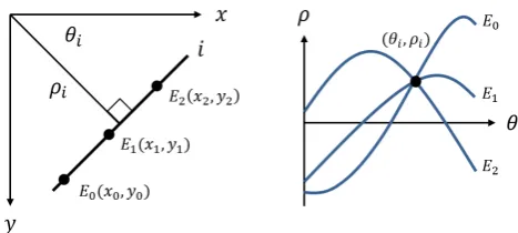
The LHT operates on binary images obtained after applying edge detection operators such as Sobel, Prewitt or Canny to determine the collinearity of edge pixels and thus to detect lines [13]. Each edge pixel(x, y)has an associated magnitude of displacementρ, and orientation of displacementθ, from the image origin. These are related by the equation
ρ=xcos(θ) +ysin(θ) (0◦≤θ◦<180◦). (1)
The HPS represents an accumulator array A(θ, ρ), that is pre-allocated in memory. The HPS is quantised with Nθ
and Nρ levels, chosen according to the applicable accuracy
requirements and memory constraints. The edge pixels within the image are processed using (1) over a discrete range of θ values [0 :δθ :θmax], where δθ is the discretisation step and
θmax is the maximum value of θ. The resulting parameters
Fig. 1: LHT mapping between edge image (left) and HPS (right).
The result of voting is to create a sinusoid in the HPS for each edge pixel. Figure 1 demonstrates this relationship using three edge pixels on a line,E0(x0, y0), E1(x1, y1), E2(x2, y2),
and their corresponding Hough Parameters as calculated using (1). The sinusoids produced by edge pixels that exist on line iwithin the image intersect at a common point(θi, ρi).
After the voting process is complete, the HPS is examined for peaks. Parameter coordinates with a significant number of votes are identified, as these correspond to linear elements in the image. Reconstruction of the lines in the spatial image domain is carried out using the inverse function of (1).
A. HPS Memory Requirements
The memory requirements for the HPS using the Standard LHT can be easily calculated. The HPS is restricted in size using the maximum displacement of a line ρmax. This is
calculated for aW ∗H pixel image in (2).
ρmax=
r W
2
2
+H 2
2
(2)
This restricts the displacement parameterρin the accumu-lator array to the range[−ρmax, ρmax].
It is necessary for the HPS to store the votes of all edge pixels, therefore the limit of the third dimension of the HPS accumulator array (‘votes’) is set to the length of the image diagonal, 2ρmax. The equation to calculate the total number
of bits required to store the HPS in memory is therefore
Abits=NρNθdlog2(2ρmax)e. (3)
For example, the memory required by the HPS, for an image of 1024x1024 pixels, is 2,871,000 bits when Nθ = 180 and
Nρ = 2dρmaxe. We will later use (3) to compare memory
utilisation of the Standard LHT with our proposed method.
III. THEPROPOSEDMETHOD
In this section, we develop a memory-efficient design for the HPS, suitable for a small FPGA. We name this method, the Angular Regions - Line Hough Transform (AR-LHT). The AR-LHT is based on a modified version of the algorithm presented in [12], wherein theρaxis on the HPS was reduced by partitioning the input image into subregions. Our innovation is to instead reduce the size of the HPS along the θ axis, recognising the potential to increase memory efficiency and reduce the complexity of the FPGA architecture.
[image:2.595.309.550.134.213.2]The algorithm for the AR-LHT follows the procedure outlined in Figure 2. Two memories are pre-allocated, one for the HPS to accumulate votes, and another known as a Region Bitmap (RBM). This follows the general method and terminology of [12] to maintain a record of the edge gradient orientationθi, and displacementρi, for each vote.
Fig. 2: Overview of the AR-LHT algorithm.
The remainder of this section details the AR-LHT and the functionality of each of the blocks shown in Figure 2.
A. Calculating the Edge Gradient Orientation
The AR-LHT uses the edge gradient orientation θG of the
candidate image to approximate the direction of lines. This reduces the number of votes that are applied to the HPS by minimising the range over which θoperates.
θG is calculated by initially finding the directional
gradi-ents of a greyscale image using the horizontal and vertical Sobel filters. These filters are applied to the image through convolution, deriving approximations for the horizontal and vertical gradients, Gx and Gy, for each pixel of the input
image. This operation is normally carried out to derive edge pixels, produced by thresholding the gradient imageG, i.e.
G=qG2
y+G2x. (4)
The edge gradient orientation can then be computed using
θG= tan−1
Gy
Gx
. (5)
The value ofθG is brought into the limits of (1) by adding
180◦ ifθG<0. It can then be used in (1) asθto calculateρ.
B. Optimising the HPS
Peaks that are formed in the HPS are usually thinly dis-persed throughout the array. We can use this knowledge to reduce the total number of addressable locations in the HPS. The size of Nθ is reduced by an integer factor R. Doing
so results in an accumulator array that contains NρNθ/R
addressable memory locations. The number of bits required to store this reduced-size HPS is given in (6).
Aoptbits= NρNθdlog2(2Rρmax)e
R (6)
Figure 3 provides a graph of the HPS for both the Standard LHT and the proposed method. Our investigations found that when R > 4 and Nθ = 180, the extraction of peaks that
Fig. 3: The HPS for the Standard LHT (left), and the AR-LHT (right).
Votes can only be applied to the reduced HPS if they are in the range [0,(θmax+δθ)/R−δθ]. To ensure each vote
is applied to the HPS, inapplicable votes are adjusted into the above range. This adjusted orientation is namedθAand, while
voting, is applied to the HPS with the same value ofρ.
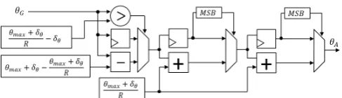
C. Calculating the Adjusted OrientationθA
To obtainθA, we first need to carry out the integer division
bθG/((θmax+δθ)/R)c. This generates a positive integer that
is used to indicate the number of times(θmax+δθ)/Rshould
be subtracted from θG to adjust it into the range [0,(θmax+
δθ)/R−δθ]. The value ofθA can then be calculated as in (7).
θA=θG−
θ
G
(θmax+δθ)/R
θ
max+δθ
R (7)
D. Separating Peaks using the RBM
The RBM is an array of sizeNθxNρx1, that is set to zero
before processing begins. The RBM is required to keep a record ofθG, and ρ, for all of the edge pixels that have been
processed using (1). It achieves this by using (θG, ρ) as an
index, and changing the value of that location to a binary ‘1’. Upon processing an entire image, the RBM is used to cross-check the parameters of peaks found in the HPS, so that they are of the correct directional orientation before reconstruction. This is performed by searching the RBM at intervals of (θmax+δθ)/Rfor the extracted value ofθA.
Due to noise pixels in the edge image, noise will also exist in the RBM and could produce incorrect results. A simple method of suppressing noise in the RBM is by filtering it with a morphological opening. This is a fast method of overcoming this problem and is suitable for FPGA implementation.
IV. IMPLEMENTATION
In our FPGA implementation δθ = 1◦, θmax = 179◦ and
R= 4. An overview of the FPGA architecture for the proposed method can be seen in Figure 4. The input RGB image is initially converted to greyscale for Sobel processing.
Throughout the remainder of this section, we will focus primarily on the memory aspects of our hardware design. In particular, the architecture for the HPS and RBM memories.
To correctly index the HPS memory array, the angle ofθG
must be in the range of[0,(θmax+δθ)/R−δθ]. As previously
[image:3.595.44.290.51.158.2]discussed, the practical limit of R is 4 when Nθ is 180. A
Fig. 4: Overview of the FPGA architecture.
simple hardware architecture designed to adjust θG into the
above range can be seen in Figure 5.
Fig. 5: Architecture to adjustθGinto[0,(θmax+δθ)/R−δθ].
The Hough parameters, ρ andθG, are used to generate an
address to access the RBM and update it accordingly. Similarly the HPS uses ρ and the adjusted angle θA to generate an
address to accumulate votes.
The HPS memory uses 36Kb Block RAM (BRAM) tiles, configured as dual-port 2K memory. The memory has two modes of operation, Vote Accumulation and Read-out and Reset. During Vote Accumulation, port A of the BRAM is configured to read the HPS vote so that it may be incremented by 1. Port B writes the updated vote back to memory.
The RBM memory uses 36Kb BRAM tiles, configured as single-port 32K memory. The RBM memory has two modes. One for Reading Parameters and another for Read-out and Reset. During Reading Parameters the RBM sets applicable address locations defined by (θG, ρ)to a binary ‘1’.
When both memories are in Read-out and Resetmode, the RBM is filtered using a morphological opening while the HPS is thresholded for peaks. Both memories are then compared to cross-check line orientation. Since the HPS isRtimes smaller than the RBM, the HPS can be read from memoryRtimes and compared to the filtered RBM over (θmax+δθ)/Rintervals.
On the final iteration, the HPS is reset.
The above architecture was developed using Xilinx System Generator. Simulations correctly produced Hough Parameters corresponding to lines in several test images. These were reconstructed and superimposed on the original images for inspection; two examples are shown in Figure 6. The output images are similar to results produced using the Standard LHT.
V. PERFORMANCE ANDRESOURCEANALYSIS
[image:3.595.306.550.190.260.2](a) A: Edge Image (b) A: Line Image (c) A: AR-LHT
[image:4.595.48.287.48.215.2](d) B: Edge Image (e) B: Line Image (f) B: AR-LHT
Fig. 6: Results of the LHT Simulation on two 1024x1024 images.
The standard LHT requires 2,871,000 bits of memory for an image of 1024x1024 pixels. The xc7z010-1 device would be unsuitable for implementation as it only contains 2,211,840 bits of dedicated FPGA memory. However, it can apply the AR-LHT to the same image resolution due to its memory-efficient HPS. The AR-LHT requires 1,474,560 bits, saving 48.64% of memory as compared to the Standard LHT.
Ser and Siu [12], developed an LHT algorithm for a reduced memory HPS. Their algorithm was applied to an image of 384x256 pixels and achieved 50% saving in memory as compared to the Standard LHT. However, our AR-LHT was able to save 58.13% when operating on the same image resolution, as shown in Table I.
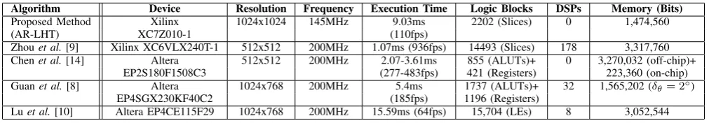
Table II provides implementation results of this work and the results from other published FPGA implementations of the LHT, three of which targeted Altera devices. As Xilinx and Altera devices are not directly comparable for total resource cost, and as our work focuses on memory optimisation, we compare memory consumption and execution time.
Zhouet al.[9] achieved a low-latency LHT architecture for an image of 512x512 pixels, at the expense of high memory consumption. Our work, the AR-LHT, saves approximately 86% of memory for the same image size.
[image:4.595.304.553.75.134.2]Chenet al.[14] implemented the HPS in off-chip memory, for an image of 512x512 pixels. By comparison, our AR-LHT saves approximately 87% of overall memory and adds the flexibility to cater for more than one image resolution. The execution time of this implementation would be dependant on the bandwidth and speed of the off-chip memory in use.
TABLE I: Results of this work for different resolutions, when R= 4,δθ= 1◦ andθmax= 179◦.
Resolution Execution Memory (Bits)
(pixels) Time AR-LHT Standard LHT % Saved
384x256 1.25ms 313,344 748,440 58.13 512x512 2.71ms 442,368 1,306,800 66.15 1024x768 7.01ms 1,345,536 2,534,400 46.90 1024x1024 9.03ms 1,474,560 2,871,000 48.64
Guanet al.[8] created a system which applied the LHT to a video stream. They reduced the total memory requirements of the HPS, by setting the discretisation step ofθto 2◦(δθ= 2◦).
This has the effect of reducing the accuracy of line detection, unlike our work, which still achieves δθ = 1◦. Even for
unequal δθ, the AR-LHT provides a memory saving of 16%.
Lu et al. [10] developed a shift-and-add LHT architecture with δθ set to 0.8952◦. This achieved better accuracy of
extracted lines whilst increasing the memory requirements of the HPS. If this approach was combined with the AR-LHT (a possible avenue of future work), the HPS could become more memory-efficient while also improving accuracy.
VI. CONCLUSION
This paper has presented the AR-LHT, a memory-efficient algorithm for the detection of lines in images. It was demon-strated that the memory consumption of the HPS could be reduced by exploiting the thin dispersion of peaks within it. We found that two separate, smaller memories (a reduced-size HPS across the θdimension, and a 1-bit RBM) could be used in conjunction to substantially reduce memory utilisation compared to the Standard LHT. After voting was complete, the RBM was used to determine the true orientation of detected peaks in the reduced HPS. The incorporation of a morphological opening post-processing stage (applied to the RBM) was crucial in the success of the proposed method.
The AR-LHT algorithm was developed using Xilinx System Generator. A series of simulations were carried out on a set of test images. Results demonstrated that the output Hough Parameters correlated successfully with lines in the original test image. The hardware architecture was then synthesised and implemented using Xilinx tools, resulting in very efficient resource requirements in comparison to similar work. An im-age of 1024x1024 pixels was found to save 48.64% of memory compared to the Standard LHT. The FPGA architecture was capable of operating at 145MHz, and can process the image in 9.03ms, equivalent to a frame rate of 110fps.
TABLE II: Results of the proposed method and comparison with related works
Algorithm Device Resolution Frequency Execution Time Logic Blocks DSPs Memory (Bits)
Proposed Method Xilinx 1024x1024 145MHz 9.03ms 2202 (Slices) 0 1,474,560
(AR-LHT) XC7Z010-1 (110fps)
Zhouet al.[9] Xilinx XC6VLX240T-1 512x512 200MHz 1.07ms (936fps) 14493 (Slices) 178 3,317,760 Chenet al.[14] Altera 512x512 200MHz 2.07-3.61ms 855 (ALUTs)+ 0 3,270,032 (off-chip)+
EP2S180F1508C3 (277-483fps) 421 (Registers) 223,360 (on-chip) Guanet al.[8] Altera 1024x768 200MHz 5.4ms 1737 (ALUTs)+ 32 1,565,202 (δθ= 2◦)
EP4SGX230KF40C2 (185fps) 1196 (Registers)
[image:4.595.44.555.631.719.2]REFERENCES
[1] P. V. C. Hough, “Machine analysis of bubble chamber pictures,” in Proceedings, 2nd International Conference on High-Energy Accelerators and Instrumentation, HEACC, CERN, Geneva, Switzerland, Sep. 1959, pp. 554–558.
[2] R. O. Duda and P. E. Hart, “Use of the Hough transformation to detect lines and curves in pictures,”Commun. ACM, vol. 15, no. 1, pp. 11–15, Jan. 1972.
[3] F. O’Gorman and M. B. Clowes, “Finding picture edges through collinearity of feature points,” IEEE Transactions on Computers, vol. C-25, no. 4, pp. 449–456, April 1976.
[4] L. A. F. Fernandes and M. M. Oliveira, “Real-time line detection through an improved Hough transform voting scheme,” Pattern Recognition, vol. 41, no. 1, pp. 299–314, 2008.
[5] L. Xu, E. Oja, and P. Kultanen, “A new curve detection method: Randomized Hough transform (RHT),” Pattern Recognition Letters, vol. 11, no. 5, pp. 331–338, 1990.
[6] N. Kiryati and Y. Eldar, “A Probabilistic Hough Transform,” Pattern Recognition, vol. 24, no. 4, pp. 303–316, 1991.
[7] J. Matas, C. Galambos, and J. Kittler, “Robust Detection of Lines Using the Progressive Probabilistic Hough Transform,” Computer Vision and Image Understanding, vol. 78, no. 1, pp. 119–137, 2000.
[8] J. Guan, F. An, X. Zhang, L. Chen, and H. J. Mattausch, “Real-time straight-line detection for XGA-size videos by hough transform with parallelized voting procedures,” Sensors (Switzerland), vol. 17, no. 2, 2017.
[9] X. Zhou, Y. Ito, and K. Nakano, “An FPGA Implementation of Hough Transform using DSP blocks and block RAMs,”Bulletin of Networking, Computing, Systems, and Software, vol. 2, no. 1, pp. 18–24, January 2013.
[10] X. Lu, L. Song, S. Shen, K. He, S. Yu, and N. Ling, “Parallel Hough Transform-based straight line detection and its FPGA implementation in embedded vision.”Sensors (Basel, Switzerland), vol. 13, no. 7, pp. 9223–9247, 2013.
[11] J. Illingworth and J. Kittler, “The Adaptive Hough Transform,”IEEE Transactions on Pattern Analysis and Machine Intelligence, vol. PAMI-9, no. 5, pp. 690–698, 1987.
[12] P.-k. Ser and W.-c. Siu, “Memory compression for straight line recog-nition using the Hough transform,” vol. 16, no. February, pp. 133–145, 1995.
[13] R. Gonzalez and R. Woods, Digital Image Processing. Pearson Education, 2011.