UNIVERSITI TEKNIKAL MALAYSIA MELAKA
DESIGN OF SINGLE PHASE H-BRIDGE MULTILEVEL
INVERTER BY USING MICROCONTROLLER
This report submitted in accordance with requirement of the Universiti Teknikal Malaysia Melaka (UTeM) for the Bachelor Degree of Engineering Technology Bachelor’s Degree of Electrical Engineering Technology (Industrial Power) with
Honours
by
NUR ADLINA BINTI AB. AZIZ B071310518
930728-01-6410
UNIVERSITI TEKNIKAL MALAYSIA MELAKA
BORANG PENGESAHAN STATUS LAPORAN PROJEK SARJANA MUDA
TAJUK: DESIGN OF SINGLE PHASE H-BRIDGE MULTILEVEL INVERTER BY USING MICROCONTROLLER
SESI PENGAJIAN: 2015/16 Semester 2
Saya NUR ADLINA BINTI AB. AZIZ
mengaku membenarkan Laporan PSM ini disimpan di Perpustakaan Universiti Teknikal Malaysia Melaka (UTeM) dengan syarat-syarat kegunaan seperti berikut: 1. Laporan PSM adalah hak milik Universiti Teknikal Malaysia Melaka dan penulis. 2. Perpustakaan Universiti Teknikal Malaysia Melaka dibenarkan membuat salinan
untuk tujuan pengajian sahaja dengan izin penulis.
3. Perpustakaan dibenarkan membuat salinan laporan PSM ini sebagai bahan pertukaran antara institusi pengajian tinggi.
4. **Sila tandakan ( )
SULIT
TERHAD
TIDAK TERHAD
(Mengandungi maklumat yang berdarjah keselamatan atau kepentingan Malaysia sebagaimana yang termaktub dalam AKTA RAHSIA RASMI 1972)
(Mengandungi maklumat TERHAD yang telah ditentukan oleh organisasi/badan di mana penyelidikan dijalankan)
(TANDATANGAN PENULIS)
Alamat Tetap:
NO. 41, JALAN MURNI,
TAMAN SURIA, 81100
JOHOR BAHRU.JOHOR
Tarikh: ________________________
Disahkan oleh:
(TANDATANGAN PENYELIA)
Cop Rasmi:
Tarikh: _______________________
iii
DECLARATION
I hereby, declared this report entitled “DESIGN OF SINGLE PHASE H-BRIDGE MULTILEVEL INVERTER BY USING MICROCONTROLLER” is the results of my own
research except as cited in references.
Signature :………
iv
APPROVAL
This report is submitted to the Faculty of Engineering Technology of UTeM as a partial fulfillment of the requirements for the degree of Bachelor of Engineering Technology Bachelor’s Degree of Electrical Engineering Technology (Industrial Power) with Honours. The member of the supervisory is as follow:
……….
v
ABSTRACT
vi
ABSTRAK
vii
DEDICATIONS
viii
ACKNOWLEDGEMENTS
Firstly, I would like to thank god for giving me the opportunities to learn and gain new knowledges and also experiences throughout my final year project. I tend to finish this report followed as I planned.
I would also like to express my appreciation to my supervisor, Mr. Syahrul Hisham Bin Mohamad @ Abd. Rahman for his guidance during the completion of this project report. Moreover, a special gratitude to Cik Suziana Binti Ahmad or guiding me on the simulation part of this project.
ix
TABLE OF CONTENTS
DECLARATION………..………..………..…iii
APPROVAL………...………..…………...iv
ABSTRACT………...………..………...v
ABSTRAK………..……….….vi
DEDICATIONS………...………..………..…vii
ACKNOWLEDGEMENT…………..………..…...viii
TABLE OF CONTENTS………...………..……...ix
LIST OF FIGURES………...……….…...xii
LIST OF TABLES………..………xiv
LIST OF ABBREVIATIONS, SYMBOLS AND NOMENCLATURE………..…...xv
CHAPTER 1: INTRODUCTION………...………..…...1
1.0 Introduction………..………..………..…..1
1.1 Problem Statement………..……...4
1.2 Objectives……….…..……….……...….4
1.3 Scope……….………...5
CHAPTER 2: LITERATURE REVIEW………...…....6
2.0 Introduction……….………..………...…..6
2.1 Power Electronic Conversion……….………...….6
2.1.1 AC to DC Converter……….…………..………...….6
x
2.1.4 DC to AC Converter……….…………...………...…8
2.2 Inverter….………..………..…..…8
2.3 Multilevel Inverter………...9
2.3.1 Diode-clamped……….………..……...9
2.3.2 Capacitor-clamped……….………...……11
2.3.3 Cascaded H-bridge………..…...12
2.3.3.1 Single-Phase Configuration of Cascaded Multilevel Inverter...14
2.3.3.1.1 Switching State of Single-Phase Cascaded Multilevel Inverter………...15
2.3.3.2 Three-Phase Configuration of Cascaded Multilevel Inverter………..………...16
2.4 Modulation..………...……18
2.4.1 Pulse-width Modulation (PWM)...………..…..……18
2.4.1.1 Linear Modulation………..……....20
2.4.1.2 Saw Tooth PWM……...………..………..…...…..21
2.4.1.3 Regular Sampled PWM………..…22
CHAPTER 3: METHODOLOGY ………..……..………..…….23
3.0 Introduction……….………..…….……23
3.1 Literature Review….………..…………...25
3.2 Inverter Circuit Design………..………...…………...25
3.2.1 Cascaded H-bridge Multilevel Inverter Circuit Design………..…….25
3.2.2 Calculations..………..……..27
3.3 MATLAB Simulation………..………….………..……...28
3.4 Inverter Fabrication……….……..………..………..………29
3.4.1 Material Selection……….……….……….………….30
3.4.1.1MOSFET.……….…….………..………..31
3.4.1.2HCPL-3120….………..32
3.4.1.3Switch Mode Power Supply (SMPS)………32
3.4.1.4Power Converter (IQ0515SA)………...33
3.4.1.5Microcontroller……….33
xi
3.5.1 Input DC Voltage……….……...………..…...35
3.6 Data Analysis…….………...………...35
3.7 Hardware Implementation of Single Phase Cascaded Multilevel Inverter…………....36
3.8 Writing Discussion and Conclusion………..…....37
CHAPTER 4: RESULTS AND DISCUSSION………...………..………….38
4.0 Introduction………..………38
4.1 Simulation and Result of Single Phase Three-level Cascaded Multilevel Inverter by using MATLAB………...38
4.2 Simulation and Result of Single Phase Five-level Cascaded Multilevel Inverter by using MATLAB……….……..40
4.3 Hardware Construction of Single Phase Three-level Cascaded Multilevel Inverter………..………...44
4.3.1 MOSFET Driving Circuit………...………..44
4.3.2 Inverter Circuit………..………….…..45
4.3.2.1 Positive Cycle Waveform………...…….….45
4.3.2.2 Negative Cycle Waveform………..……….46
CHAPTER 5: CONCLUSION………..………...………..………….48
5.0 Introduction……….………….……..48
5.1 Summary of Research………..………..48
5.2 Project Constraints………..…...49
5.3 Recommendation………...49
REFERENCES………..………..……..…….51
xii
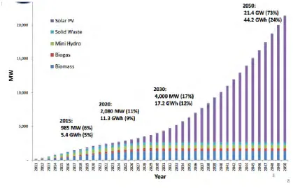
Figure 1.0: The Renewable Energy Goals in Malaysia…..………..………..…1
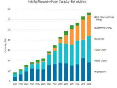
Figure 1.1: Installed Renewable Power Capacity……….……..………..….2
Figure 2.1: AC to DC converter………..………..………..…...7
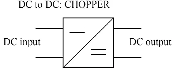
Figure 2.2: DC to DC converter………..………..………..…...7
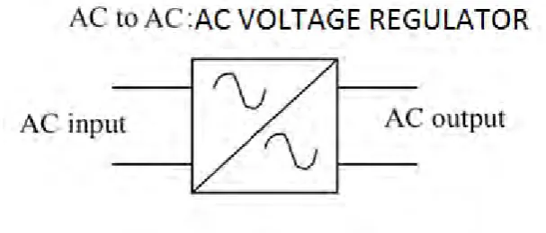
Figure 2.3: AC to AC converter………..………..………..……...8
Figure 2.4: DC to AC converter…………..………..……...………..…...8
Figure 2.5: 3-level Diode-Clamped Multilevel Inverter……….………..………...10
Figure 2.6: 3-level Capacitor-Clamped Multilevel Inverter….………...…..……...11
Figure 2.7: Single H-bridge Cell………..………..……...12
Figure 2.8: Single-phase Configuration of m-level Cascaded Inverter…...…...15
Figure 2.9: Three-phase Wye-Connected Seven Level Inverter….………..………...17
Figure 2.10: Sine modulated, unmodulated signal…...………..……...19
Figure 2.11: Sinusoidal PWM Technique……..………..………20
Figure 2.12: Linear Modulaton……….………..………….21
Figure 2.13: Saw Tooth PWM System………...………..21
Figure 2.14: Saw Tooth PWM Waveform………..…...……..22
Figure 2.15: Regulator Sampled PWM………....………22
Figure 3.1: Methodology Flowchart of Project Research………..……..24
Figure 3.2: H-bridge Cell Circuit Formed………...……...26
xiii Figure 3.4: MATLAB Simulink 3-level Cascaded H-bridge Multilevel Inverter Circuit
Design……….………...….28
Figure 3.5: MATLAB Simulink 5-level Cascaded H-bridge Multilevel Inverter Circuit Design………...………….………..….29
Figure 3.6: PCB Board………..………..…….30
Figure 3.7: Cascaded Multilevel Inverter Etching Circuit ….………...………..30
Figure 3.8: MOSFET Driving Etching Circuit…………...………...…..……….30
Figure 3.9: MOSFET……….………...…………...31
Figure 3.10: HCPL-3120………...………..………...32
Figure 3.11: Switch Mode Power Supply (SMPS)………32
Figure 3.12 : IQ0515SA Power Converter………...……33
Figure 3.13 : Arduino Uno R3………...……..34
Figure 3.14 : Overall experiment setup………34
Figure 3.15 : Battery……….35
Figure 3.16 : Oscilloscope………36
Figure 3.17 : Inverter Circuit………36
Figure 3.18 : MOSFET Driving Circuit………...…………37
Figure 4.1 : Design of Single Phase Three-Level Multilevel Inverter by using MATLAB………..………...39
Figure 4.2 : Waveform of Single Phase Three-Level Cascaded Multilevel Inverter by using MATLAB……….…...40
Figure 4.3 : Design of Single Phase Five-Level Multilevel Inverter by using MATLAB………..……...41
xiv Figure 4.6 : Waveform of Single Phase Five-Level Cascaded Multilevel Inverter by using
MATLAB………...43
Figure 4.7 : Waveform of MOSFET Driver………..………..44
Figure 4.8 : Waveform of Inverter Output for Positive Cycle………..…..….45
xv
LIST OF TABLE
xvi
NOMENCLATURE
AC - Alternating Current
DC - Direct Current
FPGA - Field-programmable gate array IGBT - Insulated Gate Bipolar Transistor
MOSFET - Metal Oxide Semiconductor Field Effect Transistor PCB - Printed Circuit Board
PWM - Pulse-Width Modulation
1
CHAPTER 1
INTRODUCTION
1.0 Introduction
Nowadays, fossil fuels are the foremost energetic contributor to the global economy. However, it can cause environmental issues such as global warming, air pollution and many more. Therefore, the demand of generating more electrical power from renewable energy is increasing as it is a green technology, which can help in solving the environmental issues. Figure 1.0 below shows the renewable energy goals, according to the Sustainable Energy Development Authority Malaysia (SEDA).
[image:17.595.111.531.419.688.2]
2 capacity.
FIGURE 1.1 : Installed Renewable Power Capacity
4 Inverters are less efficient, high cost and high switching losses. Mostly a two-level inverter is used in order to convert DC voltage to AC voltage. Although it is effective to be used to create AC, but it has a few disadvantages too. This type of inverter creates harmonic distortions in the output voltage. Besides, it also has high dv/dt stresses. It can create problem regarding those applications require low distortion in the output voltage.
A medium voltage grid also facing a difficulty in connecting one power semiconductor switches directly. Therefore, the multilevel power converter is introduced for high power and medium voltage situations.
The flying capacitor multilevel inverter is difficult to be realized since each of the capacitor need to be charged with different voltages as the voltage level increases. Besides, diode clamped multilevel inverter having the issue of expanding the multilevel because of the voltage unbalancing, the increase in the number of clamping diodes and the difficulty of disposition between the DC link capacitors and the devices when the voltage increases.
1.2 Objectives of Research
The objective of this research is mainly focus on:
a) To design the single phase h-bridge multilevel inverter
5
1.3 Scope of Research
The scope of this research is limited to the following aspects so that the research could be focused to achieve the stated objectives. This project scopes are as below:
a) To design the single phase h-bridge multilevel inverter for small power usage by using microcontroller
b) To simulate the design of single phase h-bridge multilevel inverter by using MATLAB
6
CHAPTER 2
LITERATURE REVIEW
2.0 Introduction
This chapter will discuss the theory related to this project. It contains some research principles and the topologies introduced. Moreover, this part also consists of circuit designs for different topologies of multilevel inverter. The power electronic converter can be classified into six types which are diode, rectifier, AC to DC converter, DC to DC converter, AC to AC converter, DC to AC converter, and static switches. The inverter is a type of DC to AC converter.
2.1 Power electronic conversion device
The technology of the power electronic conversion devices is developing nowadays. Due to the development, the power electronics becomes more applicable. There are many categories of power electronic conversion devices. The most famous type of convertors are AC to DC converters, DC to DC converters, AC to AC converters, and DC to AC converters.
2.1.1 AC to DC converter
7
Figure 2.1 : AC to DC converter
2.1.2 DC to DC converter
This type of converter circuit converts a fixed DC input voltage into variable DC voltage or oppositely. As the duty cycle is varied, the DC output voltage is able to be controlled. The linear regulators and switching choppers is applying this concept of conversion.
Figure 2.2 : DC to DC converter
2.1.3 AC to AC converter
[image:23.595.191.475.454.568.2]8 phase, magnitude, and power converters are particularly with an intermediary DC link.
Figure 2.3 : AC to AC converter
2.1.4 DC to AC converter
Inverters are able to produce AC output voltage from DC input voltage. It can produce the AC of controllable magnitude and frequency.
Figure 2.4 : DC to AC converter
2.2 Inverter
[image:24.595.186.476.467.572.2]