Abstract—In this paper, the authors will investigate the per-formance of a loosely synchronized (LS) code-based space–time spreading (STS) scheme in comparison to that of classic Walsh code and pseudonoise code-based STS when communicating over dispersive Nakagami-mmultipath channels. Closed-form formu-las are derived for characterizing the bit-error-rate performance as a function of the number of resolvable pathsLand the number of usersK. Our numerical results suggest that the employment of LS code-based STS scheme is beneficial in a low-user-load and low-dispersion channel scenario, where a near-single-user performance can be achieved without a multiuser detector.
Index Terms—Code-division multiple access (CDMA), Gaussian approximation, interference-free window (IFW), large area synchronized (LAS) codes, loosely synchronized (LS) codes, Nakagami-mfading.
I. INTRODUCTION
T
HE underlying philosophy of space–time spreading (STS) is reminiscent of the operating principles of space–time coding (STC) [1], where multiple replicas of the same symbol are mapped to multiple transmit antennas for the sake of achieving a transmit diversity gain. In the context of STS, the information to be transmitted may be mapped to multiple transmitter antennas with the aid of the STS codes proposed in [2], which were graphically illustrated in [3]. In simple terms, the STS codes are used for spatially spreading the information to multiple transmit antennas, again, for the sake of achieving spatial diversity.When we consider an STS-assisted direct-sequence code-division multiple-access (DS-CDMA) scheme communicating over a nondispersive channel, the employment of orthogonal spreading codes such as Walsh codes and orthogonal Gold codes [3] is ideal for the nondispersive synchronous downlink (DL) channel since the channel will not destroy the orthogo-nality of the codes when we invoke a matched filter-based rake receiver at the receiver side. However, classic orthogonal codes, e.g., Walsh codes, will lose their orthogonality when communi-cating over a dispersive multipath channel. More specifically, when the rake receiver coherently combines the different paths’
Manuscript received May 8, 2005; revised September 4, 2005 and January 15, 2006. This work was supported in part by the Virtual Centre of Ex-cellence in Mobile and Personal Communications (Mobile VCE; http://www. mobilevce.com), the Engineering and Physical Sciences Research Council, and the EU under the auspices of the NEWCOM and PHOENIX projects. This paper has formed part of the Wireless Enablers Work Area of the Core 2 Research Programme of the Mobile VCE. The review of this paper was coordinated by Prof. J. H. Cho.
The authors are with the School of Electronics and Computer Science, University of Southampton, Southampton SO17 1BJ, U.K. (e-mail: lh@ecs. soton.ac.uk).
Digital Object Identifier 10.1109/TVT.2006.878607
energy, it will inevitably combine both the multiple access interference (MAI) and the multipath interference (MPI) in case of communicating over a dispersive multipath channel. To circumvent this problem, the family of loosely synchronized (LS) codes [4], [5] has been proposed, which exhibits a so-called interference-free window (IFW). More explicitly, these codes are capable of suppressing both the MAI and MPI, provided that these interfering components arrive within the IFW. Hence, when the dispersive channel’s delay spread does not exceed the width of the IFW, we can combine all the paths’ energy without imposing any MAI and MPI interference, and hence, interference-free CDMA communication becomes possible without the employment of high-complexity multiuser detection. Furthermore, we will demonstrate that even when the channel’s delay spread does exceed the width of the IFW, the proposed LS code-based STS scheme is capable of outperform-ing the conventional STS scheme. However, the disadvantage of the LS code-based STS scheme advocated is that the number of available LS codes is limited when aiming for a specific spreading gain G. More explicitly, the number of supported users and the width of the IFWιmust satisfyK(ι+ 1)≤G[4]. To expound a little further, we can achieve a high IFW width and suppress the interference more effectively when the number of users supported in the channel is relatively low because the number of codes exhibiting a high IFW is low. By contrast, as the number of users increases, the IFW width tends to zero since all the codes having a wide IFW have been activated, and hence, the LS code-based STS scheme becomes incapable of suppressing the MAI and MPI.
Since at the time of writing no in-depth peer-reviewed IEEE journal paper study exists on the topic of LS code-aided STS CDMA/multicarrier (MC) CDMA, the novelty of this paper is that we investigate the performance of an LS code-based STS scheme in comparison to the benchmarker STS scheme of [2] when communicating over dispersive Nakagami-m multipath channels. Since LS codes were described in [4] and [5], whereas the philosophy of STS was detailed in [2] and [3], here we refrain from their detailed description.
This paper is organized follows: Section II describes the system model used, whereas Section III illustrates the detection of STS signals. Section IV characterizes the achievable bit-error-rate (BER) performance, whereas Section V discusses our numerical results. Finally, Section VI offers our conclusions.
A. LS Codes
LS codes [4] exploit the properties of the so-called orthog-onal complementary sets [4], [6]. To expound further, let us
Fig. 1. Generating the LS(N, P, W0)code using the (P×P) = (4×4) WH matrix components (1, 1, 1, 1) and (1, −1, 1, −1). (a) LS code structure. (b) Generating four LS codes.
introduce the notation of LS(N, P, W0)for denoting the family of LS codes generated by applying a (P×P)-dimensional Walsh–Hadamard (WH) matrix to an orthogonal complemen-tary code set of lengthN, as it is exemplified in the context of Fig. 1. More specifically, we generate a complementary code pair by insertingW0number of zeros both in the center and at the beginning of the complementary pair, as shown in Fig. 1(a), using the procedure described in [4]. As mentioned above, the polarity of the codesc0 ands0 shown in Fig. 1(b) during the constitution of the LS codes is determined by the polarity of the components of a WH matrix, namely, by (1, 1, 1, 1) and (1,−1, 1,−1). Then, the total length of the LS(N, P, W0)code is given byLS =N P + 2W0, and later, we will demonstrate that the total number of codes available is given by 4P. The number of these codes having an IFW of W0 chips is P, which limits the number of users that can be supported without imposing multiuser interference. Hence, the number of codes having as long an IFW as possible has to be maximized for a given code length ofLS=N P + 2W0.
Since the construction method of binary LS codes was described in [4], here, we refrain from providing an in-depth discourse, and we will focus our attention on the employment of orthogonal complementary sets [7], [8] for the generation of LS codes.
For a given complementary code pair{c0,s0}of lengthN, one of the corresponding so-called mate pairs can be written as
{c1,s1}, where we have
c1= ˜s∗0 (1)
s1=−c˜∗0 (2)
[image:2.594.37.286.68.198.2]where the superscript∗represents conjugation.˜s0denotes the reverse-ordered sequence, whereas−s0is the negated version ofs0. Note that in (1) and (2), additional complex conjugation of the polyphase complementary sequences{c0,s0}is required for deriving the corresponding mate pair{c1,s1}in comparison to binary complementary sequences [4]. Having obtained a complementary pair and its corresponding mate pair, we may employ the construction method of [4] for generating a whole family of LS codes. The LS codes generated exhibit an IFW of lengthW0. Hence, we may adopt the choice ofW0=N−1
Fig. 2. Correlation magnitudes of the LS(4, 4, 3) codes. (a) All four codes ex-hibit the same autocorrelation magnitude. (b) Cross-correlation magnitudes of
g0andg2.
to minimize the total length of the LS codes generated while providing as long an IFW as possible.
For example, the LS(N, P, W0) =LS(4,4,3)codes can be generated based on the following complementary pair [7]:
c0= + + +− (3)
s0= + +−+. (4)
Upon substituting (1) and (2) into both (3) and (4), the corre-sponding mate pair can be obtained as follows:
c1= ˜s∗0= +−++ (5)
s1=−˜c∗0= +− − −. (6)
The first set of four LS codes can be generated using the first two rows of a (P×P) = (4×4)-dimensional WH ma-trix, namely, using w0= (+1,+1,+1,+1) and w1= (+1, −1,+1,−1), as shown in Fig. 1(b). Another set of four LS codes can be obtained by exchanging the subscripts 0 and 1. Finally, eight additional LS codes can be generated by ap-plying the same principle but with the aid of the last two rows of the (4 × 4)-dimensional WH matrix, namely, using w2= (+1,+1,−1,−1) andw3= (+1,−1,−1,+1). Hence, the total number of available codes in the family of LS(N, P, W0)is given by4P. More explicitly, there are four sets of P number of LS codes. Each set has four LS codes, and the LS codes in the same set exhibit an IFW length of
[−ι,+ι], where we haveι= min{W0, N−1}. The aperiodic autocorrelation and cross-correlation function ρkk(τ), ρjk(τ)
of the codes belonging to the same set will be zero, provided that we haveτ ≤ιTc. Furthermore, the LS codes belonging to
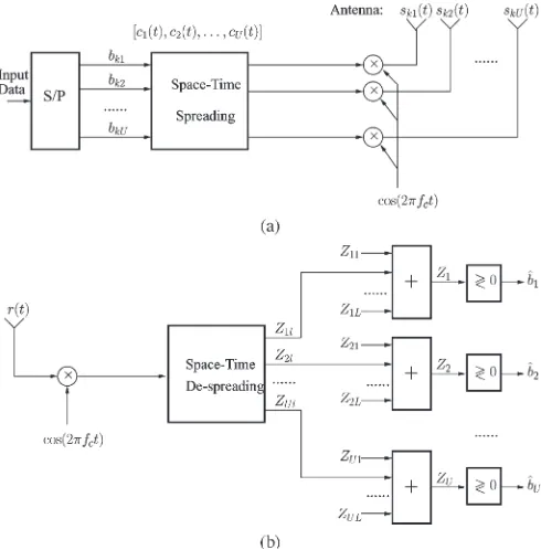
Fig. 3. Transmitter and receiver block diagram of the W-CDMA system using STS. (a) Transmitter. (b) Receiver.
may conclude that the LS(4, 4, 3) codes exhibit an IFW of±3 chip durations.
II. STS USINGINTERFERENCEREJECTIONCODES
A. Transmitted Signal
As shown in Fig. 3, the system considered in this paper consists of U antennas located at the transmitter side. The binary input data stream having a bit duration ofTb is
serial-to-parallel (S/P) converted toU parallel substreams. The new bit duration of each reduced-rate parallel substream, which we refer to as the symbol duration, becomesTs=U Tb. After S/P
conversion, the U number of parallel bits that have a U-fold higher bit duration are direct-sequence spread using the STS schemes proposed in [2] with the aid ofUnumber of orthogonal spreading sequences, e.g., Walsh codes, having a period ofU G, whereG=Tb/Tcrepresents the number of chips per bit, and
Tcis the chip duration of the orthogonal spreading sequences. As described above, based on the recommendations of [2], we have assumed that the number of parallel data substreams, the number of orthogonal spreading sequences used by the STS block of Fig. 3, and the number of transmission antennas are the same: namelyU. This specific STS scheme constitutes a subclass of the generic family of STS schemes, where the number of parallel data substreams, the number of ortho-gonal spreading sequences required by the STS block, and the number of transmission antennas may take different values. However, the study conducted in [2] has shown that the number of orthogonal spreading sequences required by STS is usually higher than the number of parallel substreams. The STS scheme has an equal number of parallel substreams, orthogonal STS-related spreading sequences, and transmission antennas, and constitutes an attractive scheme since this STS scheme is
capa-sk(t) =
2P
U2c(t)BU(t)×cos(2πfct) (7)
where P represents each user’s transmitted power, which is constant for all users,sk(t) = [sk1(t)sk2(t) · · · skU(t)]
rep-resents the transmitted signal vector of the U transmission antennas, whilec(t)andfcrepresent the DS scrambling-based
spreading waveform and the carrier frequency, respectively. In (7), the vectorc(t) = [c1(t)c2(t) · · · cU(t)]is constituted
by theUnumber of spreading waveforms assigned for the STS block, where ci(t) =UGj=0cijPTc(t−jTc), i= 1,2, . . . , U
denotes the individual components of the STS-based spread signals, and {cij} represents a spreading sequence of period
U Gfor each indexi, whilePTc(t)is the rectangular chip
wave-form spanning the chip interval [0, Tc]. In this paper, we will consider two different STS schemes. The benchmarker arrange-ment is the traditional STS scheme of [2], which is employed, e.g., in wideband CDMA (W-CDMA). In this scheme, ci(t)
can be expressed as ci(t) =wi(t)⊗PN(t) =UGj=0(wij⊗ pij)PTc(t−jTc), where wi(t) =
UG
j=0wijPTc(t−jTc)
de-notes the unique user-specific Walsh spreading sequence used by the STS scheme of Fig. 3, whereas PN(t) =
UG
j=0pijPTc(t−jTc)is the random cell-specific pseduonoise
scrambling sequence. Hence, we havecij=wij⊗pij, andcij
may also be modeled by a random spreading sequence. The employment of the PN scrambling sequence in combination with the Walsh code allows the system to reuse the user-specific Walsh codes in adjacent cells and reduce the MAI. In contrast to the benchmarker, in our proposed scheme, STS is carried out using the family of interference rejection LS codes. In this scheme, the spreading signature waveform ci(t) can be
expressed asci(t) =LSi(t) =jUG=0LSijPTc(t−jTc), where
LSi(t)denotes theith LS spreading signature waveform. More-over, we do not impose PN code-based scrambling on the LS STS codes because this would destroy their IFW. Hence, for the sake of preserving the IFW of the spreading codes, the STS scheme using LS codes refrains from invoking the conventional scheme’s scrambling operation. It is worth noting that the omission of the PN code-based spreading does not constitute a problem in conjunction with LS codes since they exhibit an IFW, and hence, they are more immune to both MAI and MPI than the Walsh codes. It has to be noted, however, that owing to the absence of the PN scrambling code, the amount of intercell interference is expected to be higher especially because the adjacent-cell interference is likely to arrive outside the IFW, where the cross correlation of the LS codes is higher than that of the cell-specific PN scrambling codes. Still considering (7), BU(t) represents the (U×U)-dimensional transmitted data
substreams according to the specific design rules of [2], so that the maximum possible transmit diversity is achieved while using relatively low-complexity signal detection algorithms.
B. Channel Model
The U number of parallel signals sk(t) = [sk1(t) sk2(t)
· · · skU(t)] are transmitted by the U number of antennas
over frequency-selective fading channels, where each parallel signal experiences independent frequency-selective
Nakagami-m fading. The complex lowpass equivalent representation of the impulse response experienced by theuth parallel signal of all users is given by [9]
hu(t) = L
l=1
hulδ(t−τl) exp (jφul) (8)
where hul, τl, and ψul represent the attenuation, delay, and
phase shift of the lth multipath component of the channel, respectively. Without loss of generality, we assume that we haveτl= (l−1)Tc, whileLis the total number of resolvable multipath components, andδ(t)is the Kronecker delta function. We assume that the phases{ψlu}in (8) are independent identi-cally distributed (i.i.d.) random variables uniformly distributed in the interval[0,2π), while theLmultipath attenuations{hul} in (8) are independent Nakagami random variables having a probability density function (pdf) of [10]–[12]
p(hul) =M
hul, m(lu),Ωul
M(R, m,Ω) =2m
mR2m−1
Γ(m)Ωm e
(−m/Ω)R2
(9)
where Γ(·) is the gamma function [9], and m(klu) is the Nakagami-mfading parameter, which characterizes the sever-ity of the fading over thelth resolvable path [13] between the
uth transmission antenna and user k. Specifically, m(lu)= 1
represents Rayleigh fading,m(lu)→ ∞corresponds to the con-ventional Gaussian scenario, andm(lu)= 1/2describes the so-called one-sided Gaussian fading, i.e., the worst-case fading condition. The Rician and lognormal distributions can also be closely approximated by the Nakagami distribution in con-junction with values ofm(lu)>1. The parameterΩul in (9) is the second moment ofhul, i.e., we haveΩul =E[(αul)2]. We assume a negative exponentially decaying multipath intensity profile (MIP) given byΩul = Ωu1e−η(l−1),η≥0, whereΩu1 is the average signal strength corresponding to the first resolvable path, andηis the rate of average power decay.
We support K synchronous CDMA users in the system and assume perfect power control. Consequently, when theK
users’ signals obeying the form of (7) are transmitted over the frequency-selective fading channels characterized by (8), the received complex lowpass equivalent signal at a given mobile station can be expressed as
R(t) = K
k=1
L
l=1
2P
U2c(t−τl)BU(t−τl)hl+N(t) (10)
whereN(t)is the complex-valued lowpass-equivalent additive white Gaussian noise (AWGN) having a double-sided spectral density ofN0, while
hl=
h1lexp jψl1 h2lexp jψl2
· · · hUl exp jψlU
, l= 1,2, . . . , L (11)
represents the channel’s complex impulse response in the context of the kth user and the lth resolvable path, where
ψlu=φul −2πfcτl. Furthermore, in (10), we assumed that the
signals transmitted by theU number of transmission antennas arrive at the receiver antenna after experiencing the same set of delays. This assumption is justified by the fact that, in the frequency band of cellular systems, the propagation delay differences among the transmission antenna elements are on the order of nanoseconds, while the multipath delays are on the order of microseconds [2], provided thatU is a relatively low number.
C. Receiver Model
Let the first user be the user-of-interest and consider a receiver using space–time despreading as well as diversity com-bining, as shown in Fig. 3(b), where the subscript of the refer-ence user’s signal has been omitted for notational convenirefer-ence. The receiver of Fig. 3(b) carries out the inverse processing of Fig. 3(a), in addition to multipath diversity combining. In Fig. 3(b), the received signal is first downconverted using the carrier frequency fc, and we assumed that the receiver is
ca-pable of achieving near-perfect multipath-delay estimation for the reference user. The descrambled signal associated with the
lth resolvable path is space–time despread using the approach of [2], which will be further discussed in Section III, to obtain
U separate variables{Z1l, Z2l, . . . , ZUl}corresponding to the U parallel data bits {b1, b2, . . . , bU}, respectively. Following
space–time despreading, a decision variable is formed for each parallel transmitted data bit of{b1, b2, . . . , bU} by equal-gain
(EG) diversity combining the corresponding variables associ-ated with the L number of resolvable paths, which can be written as
Zu= L
l=1
Zul, u= 1,2, . . . , U. (12)
Finally, theU number of transmitted data bits{b1, b2, . . . , bU}
can be decided based on the decision variables{Zu}Uu=1using the conventional decision rule of a BPSK scheme.
Above, we have described the transmitter model, the channel model, as well as the receiver model of W-CDMA using STS. Let us now describe the detection procedure of the W-CDMA scheme using STS.
III. DETECTION OFSTS SIGNALS
Letdl= [d1l d2l · · · dUl]T,l= 1,2, . . . , L—whereT
dul= √
2P Tbau1bu1h1lexp jψl1
+au2bu2h2lexp jψl2
+. . .+auUbuUhUl exp jψUl
+Ju(l),
u= 1,2, . . . , U (14)
where
Ju(l) =JSu(l) +JMu(l) +Nu(l), u= 1,2, . . . , U (15)
andJSu(l)is due to the multipath-induced self-interference of
the signal-of-interest inflicted upon thelth path signal, where
JSu(l)can be expressed as
JSu(l) = L
j=1,j=l
2P U2
× UTb+τl
τl
c(t−τj)BU(t−τj)hjcu(t−τl)dt. (16)
JMu(l)of (15) represents the multiuser interference inflicted by
the signals transmitted simultaneously by the other users, which can be expressed as
JMu(l) = K
k=2
L
j=1
2P U2
× UTb+τl
τl
c(t−τj)BU(t−τj)hjcu(t−τl)dt (17)
and, finally,Nu(l)of (15) is due to the AWGN, formulated as
Nu(l) = UTb+τl
τl
N(t)cu(t−τl)dt (18)
which is a Gaussian distributed variable having a zero mean and a variance of2U N0Tb.
LetJ(l) = [J1(l)J2(l) · · · JU(l)]T. Then, the correlator’s
output variable vectordlcan be written as
dl=
√
2P TbBUhl+J(l), l= 1,2, . . . , L (19)
whereBU is the reference user’s(U×U)-dimensional trans-mitted data matrix when we ignore the time dependence, while hlis the channel’s complex impulse response between the base station and the reference user, as shown in (11) in the context of the reference user.
only once in a given row and also in a given column of the matrixHU [2]. The matrixHU can be expressed as
HU(l) =
α11(l) α12(l) · · · α1U(l) α21(l) α22(l) · · · α2U(l)
..
. ... . .. ...
αU1(l) αU2(l) · · · αUU(l)
(21)
where αij(l) takes the form of dijhml exp(jψlm), and dij ∈ {+1,−1} represents the sign of the (i, j)th element of HU, whilehml exp(jψlm)belongs to themth element ofhl.
It can be shown furthermore with the aid of the analysis provided in [2] that the matrix HU(l) has the property of
Re{H†U(l)HU(l)}=h†lhl·I, where † denotes the complex
conjugate transpose, and Irepresents a(U×U)-dimensional unity matrix. Letting hu(l) denote theuth column ofHU(l),
the variableZulin (12) can be formulated as [2]
Zul= Reh†u(l)dl
=√2P Tbbu U
u=1
|hu l|2+ Re
h†u(l)J(l)
,
u= 1,2, . . . , U. (22)
Finally, according to (12), the decision variables associated with theU parallel transmitted data bits{b1, b2, . . . , bU}of the reference user can be expressed as
Zu= √
2P Tbbu L
l=1
U
u=1
|hu l|2+
L
l=1
Reh†u(l)J(l)
,
u= 1,2, . . . , U (23)
which shows that the receiver is capable of achieving a diversity order ofU L, as indicated by the related sums of the first term.
Above, we have analyzed the detection procedure applicable to W-CDMA signals generated using STS. Let us now derive the corresponding BER expression.
IV. BER ANALYSIS
In this section, we derive the BER expression of the STS-assisted W-CDMA system by first analyzing the statistics of the variableZu,u= 1,2, . . . , U, with the aid of the Gaussian
approximation [14].1 According to (23), for a given set of
1Before proceeding further, we would like to note that the validity of the
complex channel transfer factor estimates {hul}, Zu can be
approximated as a Gaussian variable having a mean given by
E[Zu] = √
2P Tbbu L
l=1
U
u=1
|hu
l|2. (24)
Based on the assumption that the interferences imposed by the different users, by the different paths, as well as by the AWGN constitute independent random variables, the variance of Zu
may be expressed as
Var[Zu] = E
L
l=1
Reh†u(l)J(l)
2
=L
l=1
E Reh†u(l)J(l)
2
=1
2
L
l=1
E h†u(l)J(l)
2
. (25)
Substitutinghu(l), which is theuth column ofHu(l)in (21),
andJ(l)having elements given by (15) into the above equation, it can be shown that for a given set of channel estimates {hul}, (25) can be simplified as
Var[Zu] =12 L
l=1
U
u=1
|hu l|2E
(Ju(l))2
=12L
l=1
U
u=1
|hu
l|2Var [Ju(l)] (26)
whereJu(l)is given by (15). In deriving (26), we exploited the
assumption ofVar[J1(l)] = Var[J2(l)] =· · ·= Var[JU(l)].
A. STS-Assisted CDMA Using LS Codes
Having characterized the various sources of interferecne, let us now demonstrate that with the advent of having an IFW, the LS codes are capable of suppressing both the MAI and MPI. More specifically, only the paths that fall outside the IFW will impose MAI and MPI on the decision. We assume having
TIFW=ιTc, and thejth path will inflict interference upon the
lth finger of the rake receiver only if we have
|τj−τl|> ιTc (27)
which corresponds to
|j−l|> ι. (28)
Let us first consider the effect of MPI, Similarly to the bench-mark of [2], it can be shown for the proposed LS code-based system that JSu(l) defined in (16) is also constituted by U2
terms, and each term takes the form of
Jsu(l) = L
j=1
|j−l|>ι
2P U2
UTb+τl
τl
cm(t−τj)amnbmn(t−τj)
×hnj exp jψnjcu(t−τl)dt. (29)
If we define the partial autocorrelation coefficient as
ρmm(j, l) = 1 U Tb
|τj−τl|
0
cm(t)cm(t− |τj−τl|)dt (30)
,mm(j, l) = 1 U Tb
UT b
|τj−τl|
cm(t)cm(t− |τj−τl|)dt (31)
then the integral in (29) can be expressed as
UTb+τl
τl
cm(t−τj)cu(t−τl)bmn(t−τj)dt
= (ρmm(j, l)b[−1] +,mm(j, l)b[0])U Tb. (32)
Therefore, the corresponding MPI variance of Jsu(l), u=
1,2, . . . , U can be expressed as
Var [Jsu(l)] = L
j=1
|j−l|>ι
2Ω1e(j−1)ηρ2mm(j, l) +,2mm(j, l)
×2EbTb
= L
j=1
|j−l|>ι
2e(j−1)ηρmm2 (j, l) +,2mm(j, l)
×2Ω1EbTb. (33)
For convenient formulation and comparison with the bench-marker STS scheme of [2], we define ΥS(l) =GULj=1
|j−l|>ι 2e(j−1)η[ρmm2 (j, l) +,2mm(j, l)], which is the MPI reduction
factor for thelth path, owing to the employment of LS codes. Then, the MPI variance ofVar[JSu(l)], which includes a total ofU2number ofVar[Jsu(l)]terms, can be approximated as
Var [JSu(l)]II= ΥS(l)2Ω1EbTbU/G. (34)
Having characterized the MPI, let us now focus our attention on the effects of MAI. Similarly to (30) and (31), we define the partial cross-correlation coefficients as
ρum(j, l) = 1 U Tb
|τj−τl|
0
cu(t)cm(t− |τj−τl|)dt (35)
,um(j, l) = 1 U Tb
UT b
|τj−τl|
cu(t)cm(t− |τj−τl|)dt. (36)
Hence, the integral in (17) may be expressed as
UTb+τl
τl
cm(t−τj)cu(t−τl)bmn(t−τj)dt
×hjexp jψj cu(t−τl)dt (38)
while the variance of the MAIJmu(l)can be expressed as
4Ω1EbTb K
m=1 m=u
L
j=1
|j−l|>ι
e−(j−1)ηρ2um+,2um
. (39)
Similarly to the MPI reduction factor, we define the MAI reduction factor as ΥM(l)= (GU/(K−1))Km=1
m=u
L
j=1
|j−l|>ι 2e−(j−1)η[ρ2um+,2um]. Then, the MAI variance Var[JMu(l)]
of the proposed LS code-based STS scheme, which includes a total ofU2 terms of the formVar[Jmu(l)], can be
approxi-mated as
Var [JMu(l)]II= ΥM(l)×2(K−1)UΩ1EbTbU/G. (40)
B. Probability of Bit Error
Having characterized the MAI and MPI variance, let us now quantify the achievable BER performance of the proposed system. Based on analysis [2], [15], for the traditional Walsh-code-based STS, the variance can be expressed as
Var [Ju(l)] = 2N0U Tb+2U KΩ1EbTb
q L, e−η(l−1)
G .
(41)
By contrast, the corresponding variance of Ju(l) of the LS code-based STS scheme can be expressed with the aid of (15) as
Var [Ju(l)] = 2N0U Tb+ΥS(l)2Ω1EbTbU G
+ΥM(l)(K−1)2Ω1EbTbU
G . (42)
Let us now assume that the rake receiver is capable of com-bining a maximum ofLRpaths’ energy, owing to its complexity
limitation. Then, the variance ofZucan be expressed as
Var[Zu] = 12 LR
l=1
U
u=1
|hu
l|2×Var [Ju(l)] (43)
for a given set of channel estimates {hul}using (24). Hence, the BER conditioned on hul for u= 1,2, . . . , U and l=
1,2, . . . , LRcan be written as
Pb(E| {hul})=Q
E2[Zu]
Var[Zu]
=Q
LR
l=1
U
u=1
2γlu
(44)
γlu= (E[Zul])
2
Var [Ju(l)] =γlc·
(hul)2
Ω1 . (45)
However, in the Walsh-code-based STS scheme of [2], γlc is
given by
γlc = 1 U
"
Kq(L, η)−e−η(l−1)
G +
#
Ω1Eb N0
$−1%−1
. (46)
By contrast, in the LS code-based STS scheme, γlc can be
expressed as
γlc =U1
"
ΥS(l)
G +
(K−1)ΥM(l)
G +
#
Ω1Eb N0
$−1%−1 (47)
where the MPI and MAI reduction factorsΥS(l)andΥM(l), respectively, reflect how much interference is suppressed for the
lth path with the advent of the IFW, which is mainly determined by the width of the IFW and by the number of resolvable paths, i.e., byιand L.
The average BER, i.e.,Pb(E), can be obtained by averaging
the conditional BER expression of (44) over the joint pdf of the instantaneous SNR values corresponding to the LR
mul-tipath components and to the U transmit antennas {γlu:l=
1,2, . . . , LR; u= 1,2, . . . , U}. Since the random variables
{γlu:l= 1,2, . . . , LR; u= 1,2, . . . , U} are assumed to be statistically independent, the average BER can be formulated as [17]
Pb(E) = 1 π
π/2
0
LR
&
l=1
U
&
u=1
Ilu(γlu, θ)dθ (48)
where we have
Ilu(γlu, θ) =
∞
0
exp− γlu
sin2θ
pγlu(γlu)dγlu. (49)
Since both γlu=γlc·((hul)2/Ω1) and hul obey the Nakagami-mdistribution characterized by (9), it can be shown that the pdf ofγlucan be formulated as
pγlu(γlu) =
# ml γlu
$ml γml−1 Γ(ml)exp
# −mlγlu
γlu
$
, γlu≥0
Upon substituting (50) into (49), it can be shown that [13]
Ilu(γlu, θ) =
#
mul sin2θ γlu+mul sin2θ
$mu l
. (51)
Finally, upon substituting (51) into (48), the average BER of the STS-assisted W-CDMA system using U transmission antennas can be written as
Pb(E) = 1 π
π/2
0
LR
&
l=1
U
&
u=1 #
mul sin2θ γlu+mul sin2θ
$mu l
dθ (52)
which shows that the diversity order achieved isLRU, namely
the product of the diversity due to STS and the diversity contributed by the rake receiver. Furthermore, if we assume that
mlis independent ofu, i.e., that all of the parallel transmitted
signals experience an identical Nakagami fading, then (52) can be expressed as
Pb(E) = 1 π
π/2
0
LR
&
l=1 #
mlsin2θ γlu+mlsin2θ
$Uml
dθ. (53)
V. NUMERICALRESULTS
Having characterized the analytical performance of the sys-tem, let us now consider the achievable BER performance. Sta´nczak et al.[4] concluded that when using LS codes, the widthιof the IFW and the number of usersKhas to obey the following:
(ι−1)K≤G. (54)
Furthermore, LS codes require W0 number of zero-valued chips, which are inserted in the beginning and center of the code sequence for creating the IFW. In our scenario, the LS(N, P, W0) =LS(4,32,4) codes having a length ofLS = N P + 2W0= 136were invoked, and their effective spreading gain wasLS =N P = 128since the zero-valued chips do not include the spreading gain. For the sake of maintaining the same chip rate and same spectral efficiency for both STS schemes, we set the spreading gain of the traditional STS-assisted CDMA system toG=N P + 2W0= 136. Furthermore, for the sake of simplicity, we assume that all paths have the same Nakagami fading parameter, i.e.,ml=mandl= 0, . . . , Lr−1.
[image:8.594.306.548.66.268.2]We assume that the chip rate is 1.2288 M chip/s, the channel’s delay spread is negatively exponentially distributed having a uniformly distributed mean delay in the range of [0.3,3] µs [18], and we assume that both the random and large-area synchronized (LAS) code-based systems have a chip rate of 1.2288 M chips. The number of resolvable paths is
Lp=τ /Tc+ 1 = 4, where we have τ= 3 µs. Both the
traditional STS and the LS code-based STS schemes supported
K= 32users, and the width of the IFW of the LS codes was
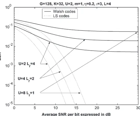
ι= 3. We can see from Fig. 4 that the LS code-based STS scheme exhibits a significantly better performance than the traditional Walsh-code-based system having the same diversity order ofLRU. The reason that the LS code-based STS scheme
Fig. 4. BER versus SNR per bit (Eb/N0) and performance comparison between the Walsh-code-based and LS code-based STS transmit diversity schemes having the same diversity order ofLR·Uwhen communicating over a Nakagami-m(m= 1)fading multipath(L= 4)channel evaluated from (53) by assuming that the average power decay rate wasη= 0.2. The remain-ing system parameters are listed at the top of the figure.
outperforms the traditional STS scheme is that the MAI and MPI are reduced as a benefit of using LAS codes, which was quantified by (53). Fig. 5 characterizes the achievable performance of these two schemes communicating over differ-ent fading channels associated with differdiffer-ent Nakagami fading parameters. More explicitly, when we havem= 1, we model a Rayleigh fading channel, m= 2 represents a Rician fading channel, while m→ ∞ corresponds to an AWGN channel. From this figure, we can observe that the LS code-based STS scheme exhibited a better performance than the traditional STS scheme regardless of the value of m. More specifically, provided that we haveLp= 4, the LS code-based STS scheme
outperformed the traditional STS scheme when communicating over different Nakagami multipath fading channels.
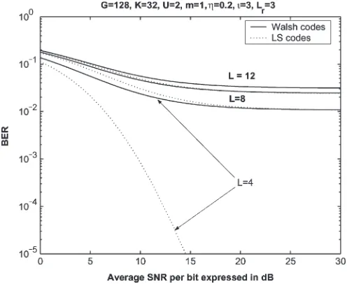
Fig. 6 shows the performance of these two systems for transmission over different dispersive channels having
L= 4, . . . ,12resolvable multipath components but assuming that only Lr= 3of these components were combined by the rake receiver owing to its limited affordable complexity. From Fig. 6, we may conclude that the LS codes are effective when the number of resolvable paths is relatively low, for example, when we haveL= 4. WhenLis increased to 8, the LS code-based STS scheme only has a slight gain over the traditional STS scheme, while when L is increased to 12, the LS code-based STS scheme performs slightly worse than the traditional STS scheme. The reason for this performance erosion is that many of the paths will be located outside the IFW whenLpis
Fig. 5. BER versus SNR per bit (Eb/N0) and performance comparison between the Walsh-code-based and LS code-based STS transmit diversity schemes when communicating over various Nakagami-mfading multipath (L= 4)channels, where Lr= 3 out of theL= 3available paths were combined by the rake receiver. The remaining system parameters are listed at the top of the figure.
Fig. 6. BER versus SNR per bit (Eb/N0) and performance comparison between the Walsh-code-based and LS code-based transmit diversity schemes and the conventional rake receiver arrangement when communicating over different dispersive Nakagami-mchannels havingL= 4,8,and12resolvable paths but only combiningLR= 3of them, owing to the maximum complexity limitations.
is replaced by using cell-specific LA codes in the LAS 2000 CDMA system proposal [19], which allows the system to retain an IFW.
[image:9.594.300.548.67.271.2]To circumvent the performance limitation of the proposed system in case of high delay spreads, we finally introduce the concept of MC LAS DS-CDMA, which allows us to extend the IFW duration by a factor corresponding to the number of subcarriers. Fig. 7 demonstrates the achievable performance of single-carrier (SC) LS assisted STS and MC LS code-based STS for a 3.884 M chips/s system. From this figure, we may conclude that the LS code-based STS-assisted MC
Fig. 7. BER versus SNR per bit (Eb/N0) and performance comparison between the Walsh-code-based and LS code-based transmit diversity schemes and the conventional rake receiver arrangement when invoking MC CDMA, where the number of subcarriersUsis 1, 2, 4, and 8, respectively. Furthermore, onlyLR= 3path have been combined, owing to the maximum complexity limitations imposed.
Fig. 8. BER versus SNR per bit (Eb/N0) and performance comparison between the Walsh-code-based and LS code-based STS transmit diversity schemes as a function of the number of users K. The remaining system parameters are listed at the top of the figure.
DS-CDMA scheme is capable of achieving the best perfor-mance tradeoff by selecting the optimum number of subcarriers
Usaccording to the channel’s delay dispersionτch. For exam-ple, we may conclude from Fig. 7 that the MC LAS DS-CDMA system usingUs= 4subcarriers exhibited the best tradeoffs in
a scenario having a delay spread ofτch= 3µs.
[image:9.594.312.556.345.551.2] [image:9.594.44.292.348.551.2]the IFW will be reduced to zero since even the codes having
ι= 0 will be required for supporting K≥32 users. In this scenario, the LS code-based STS scheme becomes incapable of effectively suppressing the MAI and MPI. Second, it may be shown that the cross correlation of LS codes outside the IFW is higher than that of the random codes; hence, LS codes may impose slightly increased interferences when the number of usersKis increased. Therefore, the LS code-based STS scheme is more effective in low-user-load scenarios, i.e., when we have
K≤G/3.
VI. CONCLUSION
The proposed LS code-based STS scheme exhibited a signif-icantly better performance than that of the traditional Walsh-code-based STS scheme [2] when the number of users sup-ported does not exceedG/3. As the number of resolvable paths
L of the channel increases, the LS code-based STS scheme only has a slight gain over the traditional STS scheme [2], owing to the fact that many of the paths arrive outside the IFW and because the autocorrelation and cross correlation of LS codes outside the IFW are higher than those of the random codes. Furthermore, when communicating in a high-user-load scenario, for example, when we have K=G, the LS code-based STS scheme may exhibit a worse performance than the traditional STS scheme of [2].
REFERENCES
[1] L. Hanzo, T. H. Liew, and B. L. Yeap,Turbo Coding, Turbo Equalisa-tion and Space–Time Coding for Transmission Over Fading Channels. Piscataway, NJ: IEEE Press, 2002.
[2] B. Hochwald, T. L. Marzetta, and C. B. Papadias, “A transmitter diversity scheme for wideband CDMA systems based on space–time spreading,”
IEEE J. Sel. Areas Commun., vol. 19, no. 1, pp. 48–60, Jan. 2001. [3] L. Hanzo, L. L. Yang, E. L. Kuan, and K. Yen,Single- and Multi-Carrier
DS-CDMA. Piscataway, NJ: IEEE Press, 2003. 1060 pages.
[4] S. Sta´nczak, H. Boche, and M. Haardt, “Are LAS-codes a miracle?” in
Proc. GLOBECOM, San Antonio, TX, Nov. 2001, vol. 1, pp. 589–593. [5] B. J. Choi and L. Hanzo, “On the design of LAS spreading codes,” in
Proc. IEEE VTC Conf.—Fall, Vancouver, BC, Canada, Sep. 2002, pp. 2172–2176.
[6] C.-C. Tseng and C. L. Liu, “Complementary sets of sequences,”IEEE Trans. Inf. Theory, vol. IT-18, no. 5, pp. 644–652, Sep. 1972.
[7] R. L. Frank, “Polyphase complementary codes,”IEEE Trans. Inf. Theory, vol. IT-26, no. 6, pp. 641–647, Nov. 1980.
[8] R. Sivaswamy, “Multiphase complementary codes,” IEEE Trans. Inf. Theory, vol. IT-24, no. 5, pp. 546–552, Sep. 1978.
[9] J. G. Proakis,Digital Communications, 3rd ed. New York: McGraw-Hill, 1995.
[10] N. Nakagami, “Them-distribution, a general formula for intensity distrib-ution of rapid fading,” inStatistical Methods in Radio Wave Propagation, W. G. Hoffman, Ed. Oxford, U.K.: Pergamon, 1960.
[11] T. Eng and L. B. Milstein, “Coherent DS-CDMA performance in Nakagami multipath fading,”IEEE Trans. Commun., vol. 43, no. 2–4, pp. 1134–1143, Feb.–Apr. 1995.
[12] V. Aalo, O. Ugweje, and R. Sudhakar, “Performance analysis of a DS/CDMA system with noncoherentM-ary orthogonal modulation in Nakagami fading,”IEEE Trans. Veh. Technol., vol. 47, no. 1, pp. 20–29, Feb. 1998.
[13] M.-S. Alouini and A. J. Goldsmith, “A unified approach for calculating er-ror rates of linearly modulated signals over generalized fading channels,”
IEEE Trans. Commun., vol. 47, no. 9, pp. 1324–1334, Sep. 1999. [14] M. B. Pursley, “Performance evaluation for phase-coded spread-spectrum
multiple-access communication—Part I: System analysis,”IEEE Trans. Commun., vol. COM-25, no. 8, pp. 795–799, Aug. 1977.
[15] L.-L. Yang and L. Hanzo, “Performance of broadband multicarrier DS-CDMA using space-time spreading assisted transmit diversity,” IEEE Trans. Wireless Commun., vol. 4, no. 3, pp. 885–894, May 2005.
[16] M. K. Simon and M.-S. Alouini, “A unified approach to the probabil-ity of error for noncoherent and differentially coherent modulation over generalized fading channels,” IEEE Trans. Commun., vol. 46, no. 12, pp. 1625–1638, Dec. 1998.
[17] ——, “A unified approach to the performance analysis of digital commu-nication over generalized fading channels,”Proc. IEEE, vol. 86, no. 9, pp. 1860–1877, Sep. 1998.
[18] W. C. Y. Lee,Mobile Communications Engineering, 2nd ed. New York: McGraw-Hill, 1998.
[19] Physical Layer Aspects of TD-LAS High Speed Packet Technology, Jul. 2001. CWTS-SWG2, LAS-CDMA.
Hua Weireceived the B.Eng. degree in wireless communication from Beijing University of Posts and Telecommunication, Beijing, China, in 1997 and the Ph.D. degree from the School of Electronics and Computer Science, University of Southampton, Southampton, U.K., in 2005.
He was with Hua Wei Technology Company, working on synchronous digital hierarchy system software development and with Motorola China Software Center, working on code-division multiple-access system (CDMA) software development. Since 2001, he has been with the Communications Research Group, School of Electronics and Computer Science, University of Southamp-ton, SouthampSouthamp-ton, U.K., and has been involved in researching CDMA schemes designed for future generations of wireless mobile communication systems. He is the author or coauthor of about 30 papers.
Lie-Liang Yang(M’98–SM’02) received the B.Eng. degree in communications engineering from Shang-hai TieDao University, ShangShang-hai, China, in 1988 and the M.Eng. and Ph.D. degrees in communications and electronics from Northern Jiaotong University, Beijing, China, in 1991 and 1997, respectively.
Since December 1997, he has been with the Com-munications Research Group, School of Electronics and Computer Science, University of Southampton, Southampton, U.K., where he held various research posts as a Visiting Postdoctoral Research Fellow, a Research Fellow, and a Senior Research Fellow. He currently holds an academic post as a Reader. From June 1997 to December 1997, he was a Visiting Scientist with the Institute of Radio Engineering and Electronics, Academy of Sciences of the Czech Republic, Prague. He has been involved in a number of projects funded by the National Sciences Foundations of China, the Grant Agency of the Czech Republic, the Engineering and Physical Sciences Research Council of the U.K., and the European Union. He is the author or coauthor of more than 100 papers published in various journals and conference proceedings. His re-search has covered a wide range of areas in communications, which include data networks and security, intelligent wireless networking, error control coding, modulation and demodulation, spread-spectrum communications and multiuser detection, pseudonoise code synchronization, smart antennas, adaptive wireless systems, as well as wideband, broadband, and ultrawideband code-division multiple access for advanced wireless mobile communication systems.
Lajos Hanzo (M’91–SM’92–F’04) received the Master’s degree (Dipl. Ing.) in electronics and the Ph.D. degree from the Technical University of Bu-dapest, BuBu-dapest, Hungary, in 1976 and 1983, re-spectively, and the D.Sc. degree from the University of Southampton, Southampton, U.K., in 2004.
During his 30-year career in telecommunications, he has held various research and academic posts in Hungary, Germany, and the U.K. Since 1986, he has been with the School of Electronics and Computer Science, University of Southampton, where he holds the Chair in telecommunications. Currently, he is managing an academic research team, working on a range of research projects in the field of wireless multimedia communications sponsored by industry, the Engineering and Phys-ical Sciences Research Council of U.K., the European IST Programme, and the Mobile Virtual Centre of Excellence (VCE) of the U.K. He is an enthusiastic supporter of industrial and academic liaison, and he offers a range of industrial courses. He has coauthored 12 John Wiley/IEEE Press books totaling about 9000 pages on mobile radio communications, published more than 600 research papers, organized and chaired conference sessions, presented overview lectures, and been awarded a number of distinctions.