promoting access to White Rose research papers
White Rose Research Online
Universities of Leeds, Sheffield and York
http://eprints.whiterose.ac.uk/
White Rose Research Online URL for this paper:
http://eprints.whiterose.ac.uk/4496/
Conference paper
Griffo, Antonio, Wang, J.B. and Howe, D. (2008)
State-space average modelling
of 18-pulse diode rectifier.
In: 3rd International Conference "From Scientific
Computing to Computational Engineering". 3rd IC-SCCE, 9 - 12 July 2008,
Athens, Greece.
3rd IC-SCCE
Athens, 9-12 July, 2008 © IC-SCCE
STATE-SPACE AVERAGE MODELLING OF 18-PULSE DIODE RECTIFIER
Antonio Griffo1, Jiabin Wang1 , David Howe11
Department of Electronic and Electrical Engineering University of Sheffield
Mappin Street, S1 3JD Sheffield, UK
e-mail: [email protected], [email protected]
Keywords: Power electronics, AC-DC conversion, State-space averaging
Abstract. The paper presents an averaged-value model of the direct symmetric topology of 18-pulse autotransformer AC-DC rectifiers. The model captures the key features of the dynamic characteristics of the rectifiers, while being time invariant and computationally efficient. The developed models, validated by comparison of the resultant transient and steady state behaviours with those obtained from detailed simulations can, therefore, be used for stability assessment of electric power systems with diode rectifiers, multiple power electronic converter-controlled loads and electrical drives*.
1 INTRODUCTION
The technological trend towards an increased utilisation of electrical power in “more electric” vehicles is posing new challenges in terms of modelling and analysis. Complex power systems, such as those currently investigated for future aircrafts applications, result from the interconnection of several nonlinear and time-varying components with dynamics whose time-scales span several orders of magnitude, ranging from relatively slow phenomena related to generator's voltage or mechanical loads regulations to comparatively faster electrical transients caused by the high frequency switching of power electronics based devices. Due to their switching behaviour power electronics based converters, widely used for dc supplies and for inverter-fed electrical drives, are intrinsically variable structure systems with the algebraic-differential equations describing their dynamics changing in correspondence with the switching events. Averaging techniques have been proposed to filter out
high frequency switching behaviour of power electronics devices[1]-[2], allowing computationally efficient
analysis of relatively slower dynamics such as those involved in the destabilizing phenomena which may arise due to the interaction between tightly regulated loads and energy storage components[3]-[4].
Averaged value models of 6-pulse and 12-pulse AC to DC converters have been derived in the past[5]-[7] also
taking into account the complex interactions with a synchronous generator[8]-[9]. However more complex
arrangements such as 18-pulse rectifiers are required for future "more electric" aircrafts in order to comply with stringent requirements on the quality of power supply to both AC and DC loads for military and civilian aircrafts[10]-[11]. Several different topologies of 18-pulse rectifiers have been proposed each with particular advantages and drawbacks[12][13].
After a circuital description of the model employed, the averaged-value model of the direct symmetric topology of 18-pulse AC-DC rectifier is analytically derived in the paper. The model is shown to capture the key features of the dynamic characteristics of the rectifier while being time invariant and computationally efficient. Comparisons of the resultant transient and steady state behaviours with those obtained from detailed simulations are presented to validate the analytically derived equations. The obtained model can therefore be used for stability assessment of electric power systems with diode rectifiers, multiple power electronic converter-controlled loads and electrical drives.
2 STATE SPACE AVERAGING
State-space averaging is extensively used for analysis and control design of switching power electronics converters[1]-[2]. For periodic waveforms x(t) the fundamental component state-space averaging is given by the one-cycle average:
*
Antonio Griffo, Jiabin Wang, and David Howe
( )
∫
( )
−
=
tT t
d
x
T
t
x
1
τ
τ
(1)where T is the period. Differentiating (1) with respect to time the following key property of the state-space average is obtained:
( )
x
( )
t
dt
d
t
x
dt
d
=
(2)
Equations (1) and (2) are the DC component of the generalized multi-frequency averaging technique[2].
Alternative averaging methods have been proposed to consider systems of differential equations with discontinuous right-hand side[1].
3 AVERAGE MODELLING OF 18-PULSE RECTIFIER
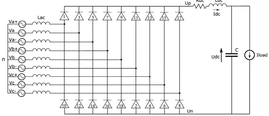
A schematic of the direct symmetric topology for the 18-pulse rectifier is shown in Fig. 1. Three sets of three phase voltages constituting a nine-phase voltage system are generated by an Auto-Transformer (AT) from the three-phase input voltages. Several winding arrangements have been proposed to generate the required phase-shift of ±40 electrical degrees[12][13]. Three three-phase diode bridge rectifiers are connected to the nine-phase source, whereas their DC output terminals are directly connected in parallel. Each diode conducts the DC current
for 1/18th of a fundamental period. DC and AC currents transformed to a synchronous reference are therefore
periodic with T=1/(18*f) , where f is the generator’s fundamental frequency. An equivalent schematic of the
Auto-Transformer Rectifier Unit (ATRU) is illustrated in Fig. 2, where Lac is the equivalent AT leakage and
[image:3.595.191.414.362.473.2]cable inductance reflected to the secondary. An RLC passive filter is connected at the output of the rectifier.
Figure 1: Schematic of a 18-pulse autotransformer and rectifier unit connected to an AC source
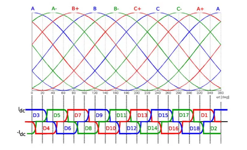
[image:3.595.90.539.540.733.2]Figure 3: Nine-phase voltages and diode conduction sequence
The ideal nine-phase voltage system generated by the AT is shown in Fig. 3 along with rectifier’s diode
conduction sequence. The DC current idc during conduction is assumed constant in the following derivations.
The commutation angle μ can be derived by analyzing the commutation process with appropriate boundary
conditions as:
⎟⎟
⎠
⎞
⎜⎜
⎝
⎛
−
=
9
sin
1
arccos
π
ω
μ
m dc ac
V
i
L
(3)
where ω=2πf and Vm is the AC voltage magnitude.
3.1 DC current with commutation angle μ less than π/9 rad
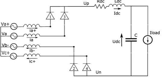
[image:4.595.76.553.520.632.2]Figures 4 and 5 show the ATRU equivalent circuit and the diodes currents during the commutation process from phase B- to C+. The 20 electrical degree interval is divided into two periods: commutation and conduction.
[image:4.595.181.398.675.745.2]Figure 4: ATRU equivalent circuit during commutation (left) and conduction (right)
Antonio Griffo, Jiabin Wang, and David Howe
The equations governing phase currents during commutation, i.e. for
0
≤
ω
t
≤
μ
when D2, D3 and D4 conductcontemporaneously, are given by:
n c c ac c ac n b b ac b ac p a a ac a ac
U
V
i
R
dt
di
L
U
V
i
R
dt
di
L
U
V
i
R
dt
di
L
−
+
−
=
−
+
−
=
−
+
−
=
+ + + − − − (4a) (4b) (4c) while the DC current is governed by:dc n p dc dc dc
dc
R
i
U
U
U
dt
di
L
=
−
+
−
−
(5)Combining (4a)-(4c) and (5) with the current equations obtained by integrating (4b)-(4c):
(
)
(
)
sin
1 cos
9
sin
1 cos
9
a dc m b dc ac m c aci
i
V
i
i
t
L
V
i
t
L
π
ω
ω
π
ω
ω
− +=
= − +
−
= −
−
(6)and the voltages relationships:
(
)
(
/
9
)
cos
9
/
cos
cos
π
ω
π
ω
ω
−
−
=
+
−
=
=
+ −t
V
V
t
V
V
t
V
V
m c m b m a (7) yields:( )
[
]
dcm dc dc ac dc dc
ac
R
R
i
V
t
U
dt
di
L
L
⎟
+
+
−
⎠
⎞
⎜
⎝
⎛
+
−
=
⎟
⎠
⎞
⎜
⎝
⎛
+
π
ω
cos
9
cos
1
2
3
2
3
(8)The equations governing phase currents during conduction, i.e. for
μ
≤
ω
t
≤
π
/
9
when D3 and D4 conduct,are given by:
n c c ac c ac p a a ac a ac
U
V
i
R
dt
di
L
U
V
i
R
dt
di
L
−
+
−
=
−
+
−
=
+ + + (9) with: dc c dc ai
i
i
i
−
=
=
+ (10)The DC link current equation is given by:
(
)
(
ac dc)
dc m m(
)
dcdc dc
ac
R
R
i
V
t
V
t
U
dt
di
L
L
+
=
−
2
+
+
cos
+
cos
−
9
−
2
ω
ω
π
(11)Taking state-space average (1) over the π/9 period of the DC current eqs. (8) and (11) and using (2) results in
dc ac D dc ac D dc ac D dc ac D
R
R
R
L
L
L
R
R
R
L
L
L
+
=
+
=
+
=
+
=
2
2
2
3
2
3
2 2 1 1 (13)3.2 DC current with commutation angle μ greater than π/9 rad
[image:6.595.161.430.207.338.2]Figures 6 and 7 show the ATRU equivalent circuit and the diodes currents during the commutation process from phase B- to C+ when the commutation angle is greater than π/9 rad. The 20 electrical degree interval is divided into two periods: commutations from D1 to D3 and from D2 to D4, and commutation from D2 to D4 while D3 is conducting.
[image:6.595.190.392.378.454.2]Figure 6: ATRU equivalent circuit during commutation for 0≤ωt≤μ−π 9
Figure 7: Commutation process with μ greater than π/9
The equations governing phase currents for
0
≤
ω
t
≤
μ
−
π
9
when D1, D2, D3 and D4 conduct are givenby: n c c ac c ac n b b ac b ac p a a ac a ac p a a ac a ac
U
V
i
R
dt
di
L
U
V
i
R
dt
di
L
U
V
i
R
dt
di
L
U
V
i
R
dt
di
L
−
+
−
=
−
+
−
=
−
+
−
=
−
+
−
=
+ + + − − − + + + (14)which can be integrated giving:
sin 1 cos
9 9
sin 1 cos
9 9
sin 1 cos
9 9
sin 1 cos
9 9 m a dc ac m a ac m b dc ac m c ac V
i i t
L
V
i t
L
V
i i t
L
V
i t
L
π
ω
π
ω
π
ω
π
ω
π
ω
π
ω
π
ω
π
Antonio Griffo, Jiabin Wang, and David Howe
Combining the DC current equation (5) with (15) yields:
3
3 3 3
1
cos
cos
cos
9
9
dc D m
dc dc
D D D
di
R
V
i
t
t
U
dt
L
L
L
π
⎡
⎛
ω
π
⎞
ω
⎤
= −
+
⎢
⎜
+
⎟
+
⎥
−
⎝
⎠
⎣
⎦
(16)where:
3 3
D ac dc D ac dc
L
=
L
+
L
R
=
R
+
R
(17)Analogously, the equation governing the DC current for
μ π
− 9≤ω
t≤π
9when the commutation from D1 toD3 has been terminated with D2, D3 and D4 being conducting is given by:
1
1 1 1
1
1 cos
cos
9
dc D m
dc dc
D D D
di
R
V
i
t
U
dt
L
L
L
π
ω
⎛
⎞
= −
+
⎜
+
⎟
−
⎝
⎠
(18)Applying state-space averaging to equations (16) and (18), it results:
3 1
3 1
3 1
3 1
9 9 2
9
9 1 1 cos 9
cos sin sin sin sin sin
9 9 9 9 9
9 1 1 2
9 9
dc D D
dc D D m D D dc D D
di R R
i
dt L L
V L L U L L
π
μ
μ
π
π
π
μ
π
μ
π
π
π
μ
π
π
π
π
μ
μ
π
⎡ ⎛ ⎞ ⎛ ⎞⎤ = − ⎢ ⎜ − ⎟+ ⎜ − ⎟⎥ ⎝ ⎠ ⎝ ⎠ ⎣ ⎦ ⎧ ⎡ ⎛ ⎞⎤ + ⎡ ⎛ ⎞⎤⎫ + ⎨ ⎢ − + ⎜ − ⎟⎥+ ⎢ − ⎜ − ⎟⎥⎬ ⎝ ⎠ ⎝ ⎠ ⎣ ⎦ ⎣ ⎦ ⎩ ⎭ ⎡ ⎛ ⎞ ⎛ ⎞⎤ − ⎢ ⎜ − ⎟+ ⎜ − ⎟⎥ ⎝ ⎠ ⎝ ⎠ ⎣ ⎦ (19)3.3 AC currents
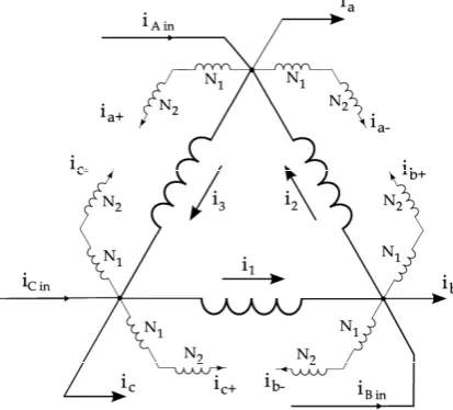
Analytical expression of the three phase AC input currents to the autotransformer unit
i
Ain,
i
B in,
i
C incan be obtained from the analysis of the winding arrangment of Fig. 8:3 2
2 1
1 3
Ain a a a
B in b b b
C in c c c
i
i
i
i
i
i
i
i
i
i
i
i
i
i
i
i
i
i
− + − + − +
=
− + +
+
=
− + +
+
=
− + +
+
(20)Transformer magneto-motive force (mmf) balance equations are derived as:
(
)
(
)
(
)
(
)
(
+ −)
(
− +)
+ − − + + − − +−
+
−
=
−
+
−
=
−
+
−
=
a c b b b a c c c b a ai
i
N
i
i
N
i
i
i
N
i
i
N
i
i
i
N
i
i
N
i
2 1 3 2 1 2 2 1 11
1
1
1
1
1
(21)where the transformer winding turn ratios necessary to generate the ±40deg phase shifts are given by N1=3.41,
N2=6.41[13]. The averaging procedure has similarly been applied to the AC currents (20), although the results are
not reported here due to space limitation.
0.098 0.1 0.102 0.104 0.106 0.108
[image:7.595.77.284.547.734.2]-300 -200 -100 0 100 200 300 Time [s] A C c u rr e n ts [A ] i Bi iGi i Ri
[image:7.595.318.524.567.722.2]Figure 9: AC current waveforms of ATRU when
4 NUMERICAL SIMULATIONS
Numerical simulations have been carried out to validate the analytically derived model by comparing the resulting waveforms with those obtained from simulating a detailed diode-switching model of the ATRU. Figure 9 shows the AC current drawn by the ATRU when it supplies a resistive load whose power consumption is changed from 170kW to 90kW at t=0.1s, while Figs. 10 and 11 compare the steady-state DC voltage and current waveforms obtained from the averaged value model with those of the detailed model after the power variation transient has settled down. Further comparisons are given in Figs. 12 and 13 for the waveforms of d- and q- axis components of the ATRU AC input currents transformed to a synchronously rotating reference frame. As will be seen, a good agreement between the two models in both transient and steady states has been achieved, albeit the switching harmonics due to diode commutations are not present in the averaged value model.
0.2 0.201 0.202 0.203 0.204 0.205 0.206 0.207 0.208 0.209 619.11
619.12 619.13 619.14
DC v
o
lt
a
g
e
(
V
)
0.2 0.201 0.202 0.203 0.204 0.205 0.206 0.207 0.208 0.209 612
612.05 612.1 612.15 612.2
Time (s)
D
C
v
o
lt
ag
e
(V
)
detailed model
[image:8.595.313.524.222.382.2]averaged model
Figure 10: DC voltage obtained with detailed (top) and averaged model (bottom)
0.2 0.201 0.202 0.203 0.204 0.205 0.206 0.207 0.208 0.209 146.6
146.65 146.7 146.75
DC c
u
rr
e
n
t (
A
)
0.2 0.201 0.202 0.203 0.204 0.205 0.206 0.207 0.208 0.209 145
145.02 145.04 145.06 145.08 145.1
Time (s)
DC c
u
rr
e
n
t (
A
)
detailed model
[image:8.595.73.281.222.382.2]averaged model
Figure 11: DC current obtained with detailed (top) and averaged model (bottom)
0.095 0.1 0.105 0.11 0.115
150 200 250 300 350
Time [s]
Id
[A
]
Id averaged model Id detailed model
Figure 12: D-axis component of AC currents obtained with detailed (red) and averaged model (blue)
0.095 0.1 0.105 0.11 0.115
-90 -80 -70 -60 -50 -40 -30 -20 -10 0
Time [s]
Iq
Iq averaged model Iq detailed model
Figure 13: Q-axis component of AC currents obtained with detailed (red) and averaged model (blue)
5 CONCLUSION
[image:8.595.316.517.442.587.2] [image:8.595.81.278.443.587.2]Antonio Griffo, Jiabin Wang, and David Howe ACKNOWLEDGEMENT
The authors would like to thank the European Commission for the financial support and the MOET Consortium for the permission of publishing the paper.
REFERENCES
[1] Krein, P.T., Bentsman, J., Bass, R.M., Lesieutre, B.L., "On the use of averaging for the analysis of power electronic systems", IEEE Trans. Power Electronics, vol. 5, n. 2, Apr. 1990, pp. 182-190
[2] Sanders, S.R., Noworolski J.M., Liu X.Z., Verghese G.C., "Generalized averagin method for power
conversion circuits", IEEE Trans. Power Electronics, vol. 6, n. 2, Apr. 1991, pp. 251-259
[3] Emadi, A.; Khaligh, A.; Rivetta, C.H.; Williamson, G.A., "Constant power loads and negative impedance
instability in automotive systems: definition, modeling, stability, and control of power electronic converters and motor drives", IEEE Trans. on Vehicular Technology, vol. 55, n. 4, July 2006 pp. 1112-1125
[4] Han L., Wang J., Howe D., “Stability assessment of distributed DC power systems for ‘more electric’
aircraft”, Proc. 4th IET International conference on Power Electronics, Machines and Drives, York, UK, 2008, pp. 661-665.
[5] Zhu, H., Burgos, R.P., Lacaux, F., Uan-Zo-li, A., Lindner, D.K., Wang, F., Boroyevich, D., 2005,
"Average modeling of three-phase and nine-phase diode rectifiers with improved AC current and DC voltage dynamics", 31st Annual Conference of IEEE Industrial Electronics Society, IECON 2005.
[6] Baghramian, A., Forsyth, A.J., "Averaged-value models of twelve-pulse rectifiers for aerospace
applications", Second International Conference on Power Electronics, Machines and Drives, 2004. (PEMD 2004).
[7] L. Han, J. Wang and D. Howe, “State space average modelling of 6- and 12-pulse diode rectifiers”, Proc. of
12th European Conference on Power Electronics and Applications (EPE) 2007, Aalborg, Denmark, Paper
ID 639. 2007.
[8] Sudhoff, S.D., Wasynczuk, O., "Analysis and average-value modeling of line-commutated
converter-synchronous machine systems", IEEE Trans. on Energy Conversion, vol. 8, n. 1, Mar. 1993, pp. 92-99. [9] Jatskevich, J., Pekarek, S.D., Davoudi, A., "Fast procedure for constructing an accurate dynamic
average-value model of synchronous machine-rectifier systems", IEEE Trans. on Energy Conversion, vol. 21, n.2, June 2006, 435-441
[10] Singh, B.; Gairola, S.; Singh, B.N.; Chandra, A.; Al-Haddad, K., "Multipulse AC–DC Converters for
Improving Power Quality: A Review", IEEE Trans. on Power Electronics, vol. 23, n. 1, Jan. 2008 pp. 260-281
[11] USA Department of Defense, "MIL-STD 704F Aircraft electric power characteristics", March 2004 [12] Uan-Zo-li, A., Burgos, R., Wang, F., Boroyevich, D., Lacaux, F., Tardy, A., "Comparison of
prospective topologies for aircraft autotransformer-rectifier units", The 29th Annual Conference of the IEEE Industrial Electronics Society, IECON '03.
[13] Chivite-Zabalza, F.J., Forsyth, A.J., Trainer, D.R., "Analysis and practical evaluation of an 18-pulse rectifier for aerospace applications", Second International Conference on Power Electronics, Machines and Drives, 2004.
[14] Mohan, N., Undeland, T., Robbins, W., “Power electronics: converters applications and design”, 3rd