XXX-X-XXXX-XXXX-X/XX/$XX.00 ©20XX IEEE
Integrated Charging of EVs Using Existing LVDC
Light Rail Infrastructure: A Case Study
Kyle Smith Electrical & Electronic
Engineering University of Strathclyde
Glasgow, Scotland [email protected]
Lewis Hunter Electrical & Electronic
Engineering University of Strathclyde
Glasgow, Scotland [email protected]
Colin Kerr Engineering Manager
Edinburgh Trams
Prof. Stuart Galloway Electrical & Electronic
Engineering University of Strathclyde
Glasgow, Scotland [email protected]
Michael Kellett Sustainability Officer Edinburgh City Council
Prof. Campbell Booth Electrical & Electronic
Engineering University of Strathclyde
Glasgow, Scotland [email protected]
Abstract— This paper outlines an approach to integrating electric vehicle (EV) charging systems to existing low voltage direct current (LVDC) public electrical transport infrastructure. Existing utility networks face challenges of accommodating a multitude of new connections associated with the adoption of EV charging infrastructure but when present, electrical light rail or tram networks represent a good opportunity to provide fast construction and less disruptive city centre charging implementation. Light rail network operation requires immediate power capacity to be available from any point on the network but if this margin were to be relaxed it opens up opportunities for sharing the available capacity with EV charging systems. This paper presents an electrical capacity assessment based on four separate charging control strategies applied to the public tram system in the City of Edinburgh, Scotland. The results of these studies, earthing and wider system protection requirements are considered and preliminary findings made.
Keywords— LVDC, EV, Trams, Light Rail, Charging Infrastructure
I. INTRODUCTION
Like many cities around the world the City ofEdinburgh in Scotland is adapting to the societal need for a more sustainable energy system that reduces global carbon dioxide emissions and improves local air quality. A component of this strategy is the reduction of transport emissions by transitioning to more electric transportation infrastructure. At a public level, this can be achieved by the introduction of electrified trams, buses and taxis; at a personal level this is aided by the adoption of private electric vehicles. To facilitate this transition requires connections to public electrical distribution networks to deliver the energy necessary to power these vehicles. However, as well as being costly to install, new electrical connections also take time to plan and implement [1]. With little published research findings available it is difficult at this stage of adoption to determine precisely how and where private EV users will choose to charge [2]. It is also important to consider, that in urban environments, many residents do not possess `off-street' parking areas and will consequently rely on public charging infrastructure [3]. Therefore, cities that possess alternative, potentially underutilised, electrical infrastructure such as light rail systems could offer additional power capacity in urban environments where the public electrical distribution grid may be congested. To determine the feasibility of such a proposal requires a method to identify the available
electrical network capacity and to control charging events to avoid interference with light rail operations.
Light rail train systems are generally lighter, slower and predominantly urban focussed compared to intercity, commuter trains. Subsets of light rail infrastructure are trams (also known as trolley buses and street cars), which are characterised by their presence on the street and operation amongst the existing city traffic flow and pedestrians [4]. They are almost exclusively powered by LVDC electrical networks, which can facilitate the integration of EVs by reducing the power conversion requirements for the charging infrastructure. Tram electrical networks are generally sized according to the peak power demand of two trams accelerating on the same section of network simultaneously; this means that out-with these events significant power capacity is available.
In this paper the operating characteristics of the Edinburgh tram network and a general model that can be applied to other tram networks for the purpose of assessing available power capacity and control solutions for the integration of EV charging infrastructure is presented.
II. BACKGROUND
In 2017 6.6 million passengers were recorded on the Edinburgh tram network with a peak daily usage of 42,000 customer journeys [5]. The tram network is designed to cope with the simultaneous acceleration of multiple trams, with each tram drawing up to 1,300 A (approximately equivalent to 1 MW assuming a nominal supply voltage) [6]. Therefore, when trams are not accelerating there is unused power capacity available, which could be used to charge plug-in electric vehicles.
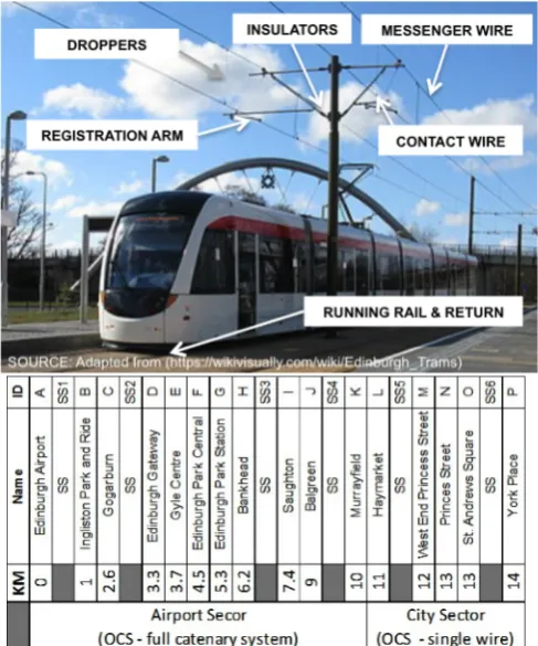
Figure 1 provides a simplified representation of the tram network stations, locations and distance of substations, with an overview of the electrical overhead catenary system (OCS). Each of the six substations on the Edinburgh tram network has a maximum power capacity of 1,200 kW. If this is multiplied across the existing tram network there is a theoretical maximum power available of 7,200 kW. However, Edinburgh-Trams, the tram operating company, currently purchase capacity of 490 kW at each substation from the local distribution network operator (DNO), Scottish Power Energy Networks, and operate the tram system within this capacity threshold. Therefore, the total tram contracted power capacity on the main line is 2,940 kW. An additional 1,245 kW of capacity is contracted at the tram depot sub-station but this is not considered in this study.
When interfacing to the Edinburgh Trams’ distribution network, sufficient power capacity must be available for tram acceleration. The connection of additional EV loads must therefore avoid interfering with normal tram operations and still allow operation within the contracted power capacity. Using a ‘smart’ grid controller it is hypothesised that the charging power requirement of EVs can be reduced during or prior to a tram’s acceleration then subsequently increased when tram acceleration is complete. Night periods, where only training or ‘ghost trams’ occasionally run, offers significant opportunity for mass charging with little power restriction.
III. ENERGY CAPACITY ASSESSMENT
Prior to conducting detailed technical integration studies, it is necessary to verify the available power and energy
capacity based on the existing tram operations. Edinburgh Trams have provided the half-hourly energy consumption from each of the six tram network substations for the duration of 2017. Figure 2 presents a box and whisker plot of the half-hourly aggregated energy demand for the tram substations, which indicates a moderate variation in energy demand throughout the year. The median energy demand is represented by the midpoint of the boxes, the upper and lower ends of the boxes represent the 75th and 25th percentiles, and the whiskers/tails indicate the maximum and minimum values that are not considered outliers - red crosses represent outlying data points. The off-peak, night periods, with significantly reduced demand and very little Fig. 1. Tram network layout: overhead catenary system (OCS),
[image:2.595.46.290.58.351.2]stations and substation locations.
[image:2.595.309.540.59.159.2]Fig. 2. Recorded half-hourly energy demand for the Edinburgh tram network from 1st January 2017 to 31st December 2017.
[image:2.595.306.545.196.296.2]Fig. 3. P50 and P90 tram network contracted power capacity available for EV charging, based on tram operations in 2017.
Fig. 4. P50 and P90 tram network technical power capacity available for EV charging, based on tram operations in 2017.
[image:2.595.306.550.329.434.2] [image:2.595.307.552.465.568.2]variability in energy use are clearly shown in Figure 2. The within day profile follows the scheduled tram timetable: a growing number of trams being ‘energised’ early in the day, a relatively stable number operating within day and into the evening, and trams retiring to the depot towards the end of the day.
A) Available Power Capacity for EV Charging
In assessing the economic feasibility of interconnecting EV chargers to the tram network, it is necessary to determine the number of EV users that can receive a charging service over a fixed period of time. This may be achieved by considering a 24-hour period and examining the available energy as well as power capacity available on the tram network. The average power availability during a half-hour period will dictate the number of active EV chargers that the tram network can supply. This power availability is equal to the contracted power capacity for each substation, minus the tram power demand at any moment in time. Since the tram electrical demand changes from day to day and seasonally, it is useful to consider the percentage of time in a year that specific power capacity is available for EV charging. The energy demand data from Figure 2 is therefore converted into P90 and P50 power availability profiles to indicate the percentage of the year that the spare electrical capacity on the tram network is available for EV charging. The P90 power availability is considered a more conservative estimate of the available power for any half-hour period; it indicates the amount of spare tram power capacity that is available for 90% of the year. The design and installation of charging infrastructure should therefore remain within the P90 power availability capacity. The P50 and P90 power availability profiles are presented in Figure 3 based on the existing contracted power capacity of 2,950 kW, and the technical power capacity rating of 7,200 kW is presented in Figure 4. It is acknowledged that the DNO may not have sufficient capacity on their network to support the full demand of 1,200 kW from each of the six substations. Further discussions are required to understand the capacity limitations from the DNO network’s perspective and to determine the full technical power capacity available to the tram network.
B) Contribution to Future EV Charging Demand
It is clear that significant power and energy capacity exists both within the current contracted threshold of 2,940 kW and the theoretical technical potential of 7,200 kW. It is difficult to accurately quantify the impact that this available electrical capacity will have on future charging demand as the demand from EVs is highly dependent on user behaviour, type of electric vehicle (private, taxi or bus), the battery capacity of the vehicle and location of charger [2]. It is, however, possible to develop EV charging utilisation models based on prior studies. Table 2 outlines the charging service capabilities for three different EV user types based on the P90 available contracted capacity and the future technical capacity. Figure 4 presents the demand profiles of these EV users to demonstrate that the predicted EV charging power demand remains within the P90 contracted
power availability. The user types and model assumptions can be summarised as follows:
• Electric Buses: Lothian buses are the main bus
operator in Edinburgh and they currently operate 6 electric buses with a battery capacity of 300 kWh [7]. This model assumes that the buses receive a full charge overnight, between 00:00 and 06:00, using 75 kW chargers.
• Taxis: There are currently 3,118 operational taxis in
Edinburgh [8]. Based on the historic utilisation of Charge Place Scotland’s (CPS) 50 kW rapid dc chargers, a taxi specific demand profile was created to determine the number of taxi operators that can be serviced. Current data from CPS suggests that electric taxis use public rapid chargers to ‘top-up’ their battery during the day, as the average energy transaction is 7.2 kWh. This corresponds to approximately 27 miles of range for a Nissan Leaf (a popular EV for taxis) [9].
• Residential: Based on the Average Daily Maximum
Demand charging profiles developed in the My Electric Avenue project [10], it is possible to determine the number of EVs that can be charged within the tram power capacity profile. It is assumed that no ‘smart’ charging or incentives are applied to ‘shift’ residential charging demand to off-peak periods.
The results presented in Figure 5 and Table 2 are independent assessments that are constrained by available power capacity on the tram network however, in each case, significant energy capacity remains outwith their peak charging times. Based on the charging profiles modelled in Figure 5, a practical charging implementation strategy should therefore consider an optimal combination of charging infrastructure between buses, taxis and residential charging that will maximise the utilisation of available energy capacity on the tram network over a 24-hour period.
It is important to note that this power capacity assessment is based on the whole tram network but a more detailed assessment may be required for each substation depending on the preferred integration approach. This charger integration approach and associated topology options are explored in the following section.
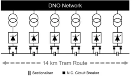
IV. ELECTRICAL TOPOLOGIES & CONTROL STRATEGIES The existing electrical connection arrangement considered in this paper for the City of Edinburgh tram system is presented in Figure 6. The tram traction power supplies are
TABLE I. TRAM NETWORK POTENTIAL EV CHARGING CAPABILITY EV Users Serviced in 24 hrs Contracted (P90) Technical (P90)
Daily energy available (MWh) 49.1 151.4 Max. power available (kW) 1674 5934
Electric Buses* 51 136
Residential (overnight)* 1500 4800
Taxis* 3118 >5000
derived from an 11 kV three phase ac public distribution network, managed by the local DNO. At each of the six tram substations the electrical power is rectified via a twelve-pulse line commutated thyristor to 750 Vdc.
The dc tram network is sectionalised into six sections, each with their own connected substation. The catenary system is based upon a 120 mm2 contact wire with wire droppers to a parallel messenger wire (120 mm2) for the majority of the network. For aesthetic purposes, the city centre uses a single contact wire with parallel-buried feeder cables [11].
Voltage regulation on the dc bus is controlled by altering the thyristor firing angle in accordance to the European Standard on supply voltage for traction systems [12]. Under normal operation, the dc side voltage will reside within the bounds of 750 (+20% | -33%) Vdc. Therefore the lowest permanent indefinite voltage is 500 Vdc while the highest is 900 Vdc under standard operating conditions [13]. Any EV charging system that is to interface with the tram electrical network must operate within this voltage variation and be controlled in a manner that does not jeopardise tram traction power.
This section outlines three different charger-tram connection topologies and discusses the control and protection strategies necessary to practically operate these integrated systems.
A. Topologies of connection
[image:4.595.56.280.69.199.2]The three EV charger and tram connection strategies proposed in this paper are outlined in Figure 7, 8 and 9. The ac side connection illustrated in Figure 7 offers the most standard connection arrangement however the purchase of suitably sized 11:0.4 kV/kV transformer and the associated civil infrastructure adds cost and land/planning requirements to this connection method.
Figure 8 demonstrates a dc connection of an EV charger to the traction supply bus bars. This offers an elegant interface but the limited number of rectifier sites on the tram network confines connection options within close proximity of existing substations which may not be optimally located for EV charging. This approach allows full access to the
available tram network power capacity due to the direct connection to the transformer-rectifier bus bar.
In Figure 9 an alternative dc connection to the overhead catenary system (OCS) is offered. This is arguably the most flexible connection arrangement as it allows connection of EV chargers at any point along the 14 km tram route. A challenge to this approach is to route the dc side cables from the OCS to EV chargers. This will require conductors to be routed above the tramway or carried through service ducts beneath the running rails.
These connection options each require a control method that will accurately regulate the power flow to EVs during charging to ensure sufficient power capacity is maintained for normal tram operations. The control options considered in this paper include: simple time-based charging control, dynamic current control, dynamic voltage control and tram position control based on readings from the tram’s on board Global Positioning System (GPS).
Fig. 7. EV charger interfaced via ac connected step down transformer and EV charging inverter.
Fig. 8. EV charger interfaced via dc/dc converter connected to dc bus bar of the traction supply.
Fig. 9. EV charger interfaced via dc/dc converter connected to dc catenary and returning rail.
[image:4.595.301.530.71.185.2] [image:4.595.305.530.193.283.2] [image:4.595.306.509.322.404.2]B. Time Based Control
In the absence of a dynamic power control approach the allowed number of EV charger connections will be limited to the unused electrical capacity of the tram network. Considering existing operational practice is to purchase minimal headroom, there is little scope to introduce EV chargers without first procuring additional capacity from the DNO. This approach could adopt a time-based charging control that may permit charging to occur during non-peak and evening periods where there is limited tram activity and demand for traction power.
C. Dynamic Current Control
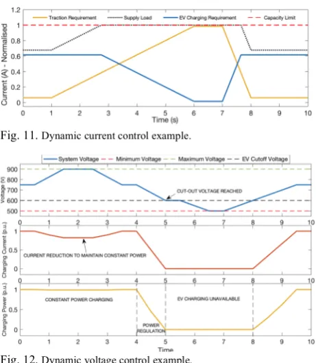
A dynamic current control approach measures the ac or dc current at the substation that supplies a section of tram network, similar in nature to the control solutions deployed in microgrid operations [14]. When an increase in current is measured it reduces the power delivery to the EV charger proportionately. Figure 10 outlines the proposed measurement location; note that the current measurement position should disaggregate traction current from EV charging current. Figure 11 illustrates a simulated representation of the proposed dynamic current control where the red dashed line represents the maximum supply current and the black dashed line the combined current demand from the tram network and EV chargers. At 1 second, tram acceleration begins to occur and just before 3 seconds the combined current demand reaches the system threshold. This requires the EV charging control to curtail charging demand within the available system capacity. This approach is best suited to ac and dc bus bar connected topologies (but may also be applied to catenary connected solutions with an appropriate communication system).
D. Dynamic Voltage Control
Dynamic voltage control offers a solution to control EV charging power when an EV charging connection is made to the OCS. Measuring the dc side voltage and using a droop control method allows chargers to respond in a predictable manner for a given recorded voltage [15] [16]. When a voltage reduction is recorded the power requirement for EV charging can be modulated appropriately. In figure 12 the tram system voltage is depicted and an arbitrary charging cut-off voltage of 600 Vdc is applied to illustrate the charging current and power response as the tram system voltage drops. In the middle plot of Figure 12, it can be seen that the EV charger regulates the current during a system voltage increase (0.5-3.5s) to maintain constant power and
then reduces charging current when the tram system voltage drops.
This approach is appealing, as it does not require additional parameter measurements and communication links to the dc/dc converter of the EV charger. Furthermore, voltage is an inexpensive parameter to measure that can provide the real time status of the tram network; this approach therefore offers a true decentralised management solution.
E. GPS / Timetable Control
The previously proposed control approaches could all be enhanced using real time inputs from the Tram SCADA (Supervisory Control and Data Acquisition) system, which records parameters such as GPS, track circuit monitoring and radio to determine the position of rolling stock on the network. In conjunction with timetables for the tram system, periods of predicted acceleration could be identified and communicated to EV chargers throughout the network. This would rely heavily upon the existing tram communication system and would require real time inputs from the SCADA system to account for periods when trams are not running to schedule.
[image:5.595.55.275.60.136.2]Ultimately, the selected charging control solution will be dependent on the chosen EV charger connection location, the control solution must prioritise the operation of the tram network by ensuring sufficient traction power is available and the power quality is maintained within the design limits. However, considering the tram network is dc based, further protection and earthing considerations are required for public safety as well as the structural integrity of utilities and nearby buildings caused by the risk of stray leakage currents from the EV charger connection and distribution points.
Fig. 10. Control Measurement position for Dynamic current control
approach. Fig. 11. Dynamic current control example.
[image:5.595.313.544.66.331.2]F. Protection & Earthing
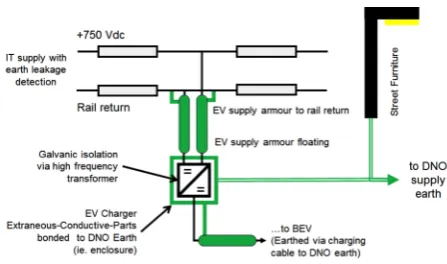
The existing tram network has an IT electrical configuration with stray current monitoring to ensure all return current is carried by the tram return rail. To interface EV charging with this network it is important that the integrity of the tram network’s earthing and protection arrangements are not adversely affected. Figure 13 presents a proposed earthing arrangement for the connection of EV chargers to the network. It is important to minimise the touch potential between the tram network and street furniture. The proposed earthing arrangement references extraneous conductive parts on the EV charging system to the street furniture earth supplied by the DNO. The armoured cables, which feed the EV charger, are bonded to the tram return rail and left floating at the EV charger.
Furthermore, suitably graded overcurrent protection on the supply side would protect faults between the supply and return on the feeder cable to the EV charger. Earth leakage protection should also be employed to ensure no unknown earth paths. It is envisaged that protection of the EV charging cable would be handled by the EV charger as outlined in IEC Standard 61851-24 [17]. A fault on the EV charger should not affect tram operation.
V. PRACTICAL CONSIDERATIONS
In designing an appropriate EV charger to tram integration solution it is also necessary to consider abnormal tram operational requirements. These may include faulted sections of the tram network, road traffic incidents, street events, working at height activities and emergency access. It is therefore important to incorporate remote disconnection of EV charging assets from the tram control room. This may be achieved with a dedicated isolation switch for each EV charger supply point on the tram network, which can be operated through the existing SCADA system.
Although measurement devices for ac and dc side current and voltage are readily available [18]; many already exist within the tram network and are accessible via the SCADA network. Dedicated ‘smart’ grid controllers or customisable programmable logic controllers have been used in numerous applications to control demand against parameters such as temperature, wind or available generation [19]. For EV charging infrastructure, the Open Charge Point Protocol [20] offers a standard approach to remote access and control of
charging systems [20]. However, additional reconfiguration of standard ac and dc EV chargers will be required to incorporate localised current and voltage measurements with a bespoke, embedded software control solution.
In implementing the charging control design it is important to consider stability between EV chargers, especially in the case of current or voltage measurement control. In the worse case scenario, ‘hunting’ may occur between EV chargers, causing the chargers’ power output to oscillate. It is therefore necessary to determine an appropriate charging ramp rate to enable differentiation between tram acceleration events and charging activation. This could be achieved by limiting the rate of change of power delivery from EV chargers to a value of less than 200 kW per second, which is approximately the rate of change of power that occurs during tram acceleration.
VI.CONCLUSIONS
This paper outlines the topology of an existing tram network in the City of Edinburgh and analyses the available power capacity for the future integration of EV charging infrastructure using a shared power capacity arrangement. A series of EV charging connection, control and protection options are discussed as part of the preliminary work in developing a pilot implementation project. From this initial study, and the tram network’s available contracted power capacity, it is clear that sufficient power and energy capacity is available to support the charging of 51 electric buses, or 1,500 personal EVs or up to 3,118 taxis during their operational shifts.
The selected connection and control strategy to take forward for implementation will depend on spatial restrictions and preferred user charging locations. However, a prudent technical approach would begin with a standard ac charging connection at one of the six substations to test the power control strategy within the available contracted power capacity, before trialling a dc connection to the tram network and the associated earthing and protection requirements.
ACKNOWLEDGMENT
The authors would like to acknowledge input from both Michael Kellet (Senior Sustainable Development Officer) and Colin Kerr (Engineering Manager) of the City of Edinburgh Council. This work has been supported through the EPSRC Centre for Doctoral Training in Future Power Networks and Smart Grids (EP/L015471/1).
REFERENCES
[1] D. Howell and et al, “Enabling Fast Charging: A Technology Gap Assessment,” US Dep. Energy (Office Energy Effic. Renew. Energy), no. October, 2017. [2] M. Nicholas and D. Hall, “Lessons Learned on Early Fast
Electric Vehicle Charging Systems,” no. July, 2018. [3] Office for Low Emissions Vehicle, “The Plug-in Vehicle
Infrastructure Strategy,” 2011.
[4] UK Office of Rail & Road, “Light rail and tramways.” [Online]. Available: http://orr.gov.uk/about-orr/who-we-work-with/railway-networks/light-rail-and-tramways. [Accessed: 07-Feb-2019].
[5] Scott-Moncrieff, “Edinburgh Trams Ltd. Statutory Accounts 2017,” 2017. [Online]. Available: Fig. 13. Proposed EV charging earthing and protection
[image:6.595.54.278.55.187.2]https://edinburghtrams.com/uploads/general/Annual_Acco unts_2017.pdf. [Accessed: 18-Jan-2019].
[6] M. Johnson, “Edinburgh gets its trams,” Rail Engineer, 2014. [Online]. Available:
https://www.railengineer.uk/2014/06/11/edinburgh-gets-trams/. [Accessed: 18-Jan-2019].
[7] Lothian Buses, “Lothian introduce the first all-electric buses to Edinburgh.” [Online]. Available:
https://www.lothianbuses.com/news/2017/09/lothian-introduce-the-first-all-electric-buses-to-edinburgh/. [Accessed: 11-Jan-2018].
[8] City of Edinburgh Council, “Electric Vehicle Infrastructure : Business Case,” no. October, 2018. [9] Edmunds, “Used 2015 Nissan LEAF Review.” [Online].
Available:
https://www.edmunds.com/nissan/leaf/2015/review/. [Accessed: 11-Jan-2019].
[10] E. Technology, “My Electric Avenue Summary Report,” 2015.
[11] City of Edinburgh Council, “Tram Design Manual,” 2005. [12] CENELEC, EN 50163: Railway applications - Supply
voltages of traction system. 2004.
[13] R. D. White, “DC electrification supply system design,” 7th IET Prof. Dev. Course Railw. Electrif. Infrastruct. Syst. (REIS 2015), p. 11 (29 .)-11 (29 .), 2015. [14] W. Su and J. Wang, “Energy Management Systems in
Microgrid Operations,” Electr. J., vol. 25, no. 8, pp. 45– 60, 2012.
[15] T. Dragičević, J. M. Guerrero, and J. C. Vasquez, “A distributed control strategy for coordination of an autonomous LVDC microgrid based on power-line signaling,” IEEE Trans. Ind. Electron., vol. 61, no. 7, pp. 3313–3326, 2014.
[16] W. Pei, W. Deng, X. Zhang, H. Qu, and K. Sheng, “Potential of Using Multiterminal LVDC to Improve Plug-In Electric Vehicle Integration in an Existing Distribution Network,” IEEE Trans. Ind. Electron., vol. 62, no. 5, pp. 3101–3111, 2015.
[17] International Electrotechnical Commission (IEC), “IEC 61851-24: Electric vehicle conductive charging system charging station,” 2014.
[18] Omni Instruments, “AC and DC Current Sensors.” . [19] D. Sharma and R. K. Mallik, “Voltage Control of a DC
Microgrid with Double-Input Converter in a Multi-PV Scenario Using PLC,” 2016 IEEE Power Energy Soc. Gen. Meet., pp. 1–5.