Modelling a laser plasma accelerator driven free electron laser
B M Alotaibi1,3
, Sh M Khalil1,2
, B W J McNeil3,4
and Piotr Traczykowski3,4
1 Physics Department, Faculty of Science, Princess Nourah Bint Abdulrahman University, Riyadh, Kingdom of Saudi Arabia 2 Plasma Physics & Nuclear Fusion Department, NRC, Atomic Energy Authority, Cairo, Egypt
3 Department of Physics, University of Strathclyde, Glasgow, G4 0NG United Kingdom 4 Cockcroft Institute, Warrington, WA4 4AD, United Kingdom
E-mail:[email protected]
Keywords:free-electron lasers, laser-plasma accelerator, puffin code, undulator
Abstract
Free-electron lasers
(
FEL
)
are the brightest, coherent sources of short wavelength radiation from the
VUV into the x-ray. There is much research interest in reducing the cost and the size of FELs by
utilising new accelerator techniques. Laser-plasma accelerator
(
LPA
)
are a promising accelerator for
next generation compact FEL light sources with many potential advantages due to the high
acceleration gradient and large peak currents they offer. The electron beams of a LPA typically have a
smaller transverse emittance, a large energy spread and tend to be of shorter duration and higher
current than conventional Radio Frequency
(
RF
)
accelerators. In this paper, a FEL driven by an
electron beam from a typical LPA was simulated using the 3D FEL simulation code Puf
fi
n. It is shown
that lowering the homogenous electron beam energy spread increases the radiation energy output in a
short undulator and , as become less than the FEL, or Pierce parameter
(
r
)
, then the peak radiation
energy increases and the saturation length reduces signi
fi
cantly as expected.
Introduction
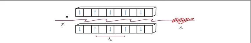
The FEL can create tunable, high-power sources from the hard x-ray to far infrared(FIR)with high brightness, coherent radiation, as has been demonstrated at many facilities worldwide[1]. Figure1shows a typical high gain FEL configuration with a highly relativistic electron beam propagating through an undulator or(wiggler) characterised by the dimensionless undulator parameter,au = eB2pumclu,where,Buis the RMS undulator magnetic
field strength,luis the undulator period,eandmare the electron charge and rest-mass respectively. The
resonant FEL wavelength is then given bylr= 2lgu2 (1+au2),
0
whereg0is the mean Lorentz factor.
A fundamental scaling parameter for a FEL that determines the strength of FEL interaction in the 1D is the dimensionless Pierce parameter(also called the FEL parameter), defined as[2]:
r g s =⎡ = ⎣ ⎢ ⎢ ⎤ ⎦ ⎥ ⎥ ⎡ ⎣ ⎢ ⎤ ⎦ ⎥ [ ] [ ] ( ) a JJ k
k I I a JJ k 16 1 8 1 u p u peak A u x u
2 2 2
2 1 3
2 2
0 3 2 2
1 3
where a planer undulator trajectory is assumed[3]with a Bessel function factor[ ]JJ =[ ( )J0 x -J1( )]x where
x=au2/2 1( +au2).The gain length of the interaction islg =lu/4pr.kp= 2Ipeak/(g0IAsx)
3 2 is the longitudinal plasma oscillation,kuis the undulator wavenumber,IA=ec r/e»17kAis the Alfven current ,
» ´
-re 2.8 10 15mis the classical electron radius,Ipeakis the peak current , andsx=syis the rms transverse
radius of the electron beam for a circular cross-sectional beam[2,3].
The normalised beam emittanceenintroduces an effective energy spread[4]in the resonant energies of the
electron beam[2,3]which may be written as: s b g = + ( ) ( ) a k a
4 1 2
n u u
r u
2 2
2
wherebis the betatron function andgris the resonant energy for the radiationfield. This may be combined with the homogenous electron beam energy spreadsg,to give a total effective energy spread of :
OPEN ACCESS
RECEIVED
10 May 2019
REVISED
17 May 2019
ACCEPTED FOR PUBLICATION
12 June 2019
PUBLISHED
24 June 2019
Original content from this work may be used under the terms of theCreative Commons Attribution 3.0 licence.
Any further distribution of this work must maintain attribution to the author(s)and the title of the work, journal citation and DOI.
seff = s2+sg2. ( )3
Some conditions are required for high gain FEL operation[1,3,5]:
The homogeneous energy spread must be less than the FEL parametersg r.
The conflicting requirements of transverse matched beam radius and radiation diffraction require that the normalised beam emittancenl g pr /4 .
To balance theau-dependent Pierce parameterrand the resulting gain lengthlg,while minimizingluand
obtaining a practical undulator gapg,undulator parametersau=2.3and(lu=15mm)were used[6]. An
undulator length of 2 m(determined from the estimated saturation length andlu)was chosen to allow for a compact set-up and to avoid refocusing optics between undulator modules enhancing FEL performance with a planar undulator design[6].
The following simulations were carried out using the code Puffin[7,8]which is a non-averaged FEL simulation code that may be used to simulate FEL parameters typical of those generated by LPA output . In contrast in[6]they used Genesis code. GENESIS and PUFFIN are considered as high gain FEL simulation codes, including clear differences between them.
In spite of the agreement between GENESIS and PUFFIN was in general excellent, it is shown that[9]for a relatively small energy modulations, the GENESIS is a sufficient tool for modeling both HGHG and EEHG beams. However in more extreme settings, such as those with very large energy modulations, the assumptions of GENESIS could cause inaccurate results[9].
Simulation results
A study wasfirst carried out for a range of parameters using the Ming Xie formalism of[10,11]. These analytical calculations of FEL performance, which does not require any significant computation, estimates important parameters, such as the gain length, while taking into account multiple electron beam and 3D effects, such as radiation diffraction of importance for short wavelength operation. The estimates so obtained are a quick and useful method for optimising FEL output and other parameters such as the gain length.
The FEL simulation code Puffin[7,8]was also used in a steady-state mode, which has periodic boundary conditions applied over one wavelength of the radiationfield/electron beam[12]. Full 3D-Puffin simulations were used to model a LPA driven FEL which assumed Gaussian distributions for the electron pulse duration and other electron parameters. An electron bunch with LPA–like parameters as given in table1was used for different values of uncorrelated energy spreads 0.0%–1.0%[6].
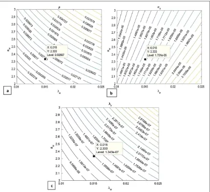
[image:2.595.120.553.62.136.2]The- Ming Xie formalism was used to determine the effect of many beam parameters in table1, such as electron beam emittance and energy spread on the undulator length to achieve high power saturated radiation output. Figure2shows contour plots of(a)Pierce parameterr(b)RMS transverse sizes of the electron beamsx y,
Figure 1.Schematic of an FEL amplifier with the electron passing through a planer undulator and emitting resonant undulator radiation.
Table 1.Output parameters from LPA.
Parameters Value parameters
Normalised emittance(en) 0.2 mm mrad
Normalised beam energy(g) 600 MeV
Peak current(Ipeak) 9.6 kA
Bunch charge current(Q) 40 pC
RMS energy spread(sg) (0.0, 0.25, 0.5, 0.75, 1.0)%
[image:2.595.240.436.210.294.2]and(c)resonant wavelength againstluandauusing the parameters of table1. This resulted in the parameters of
table2being chosen.
These parameters were then used in the Puffin simulation code in steady-state mode.
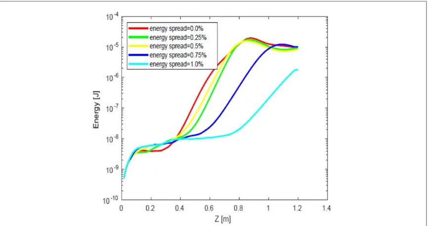
Lsatis the saturation length, which can be approximated byLsat »20Lg[13]. Figure3shows a comparison
between the radiation energy of different values of energy spreadssgin steady state mode .
3D laser-wake
fi
eld accelerator
(LWA)
driven FEL
After running Puffin in periodic(steady state)mode as above, it is seen that beam energy spreads of σγ=(0.25%–0.5%)give a reasonable gain. A full Gaussian current electron pulse beam for these values of
[image:3.595.123.553.60.454.2]energy spreads are now simulated. A beam of peak currentIpeak=9.6 kA , charge ofQ=40pC,and unchirped energy of 600 MeV was used[6]. A planar undulator period oflu =15mm with an undulator pole gap of
[image:3.595.266.408.534.607.2]Figure 2.Contour plots of(a),(b)σx,yand(c)λragainstλuandau.
Table 2.Output parameters from Ming Xie formalism.
Parameters Value parameters
r 0.0269
Lsat 0.83 m
=
g 2.5 mm was chosen to give an undulator parameter ofau=2.3[6]. These beam and undulator parameters give an FEL parameter ofr=0.0269 as above with a resonant wavelengthlr=134nm.
The electron bunch length is calculated asse= 2pcQI =0.5mm
peak which is similar to that of one cooperation lengthlc= 4lprr =0.4mm[7], so that the radiation output will then be in the weak superradiant mode of operation to give a single, short radiation pulse output[14]. Figure4shows the total radiated energy in the FEL for the Gaussian electron bunch. Figure5shows that if we have a sufficiently low value of energy spread then a relatively high peak energy can be achieved in a short undulator. Note that as the energy spread approaches the criterionsg r,then the peak energy reduces and the saturation length increases significantly as expected.
Figure6shows the intensity spectrum(∣ ˜ ∣ )A 2 plotted as function of scaled frequencyw w/
rfor two values of
energy spread=0.25% and 0.5% , for z=1.05 m through the undulator . It is seen that the maximum gain is at
ω/ωr≈0.99 for 0.25% andw w/ r»0.97for 0.5%. This is in broad agreement with small shift from resonance
(w w/ r=1)for the peak that occurs due to the effect of the emittance(n=bgerms)[13], wheree = l
p rms 4ris the
[image:4.595.121.554.61.290.2]geomertric rms emittance[4].
[image:4.595.124.551.347.568.2]Figure 3.The radiation energy as a function of distance z through the undulator for different values of energy spread.
Figure 4.3D Puffin simulation showing radiation energy as a function of distance z through the undulator in Gaussian distribution.
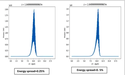
Figure7shows the temporal power of the pulse as a function of(ct-z)at saturation(z=1.05 m)for energy spreadσγ=(0.25% and 0.5%), clearly showing the reduced power whensg r.
Future work , will look to start-to-end FELs simulations using LPA in the range of soft x-ray(XFEL)between 1–10 nm[15,16]. This will requrie high quality beam with high peak current, high energy and small transverse emittance within a relatively short undulator. This can be challenging in propagating, conditioning and matching the electron beams into the undulator due to , relatively large energy spreads and divergence of the electrons at the LPA exit[17].
Conclusions
[image:5.595.122.552.60.273.2]The work on plasma accelerators is not only limited to optimisation of the qualities of electron beams; FEL performance benefits from beams with a high current, small transverse emittance and small energy spread. The undulator design is based on recent achievements in the development of undulators to optimise the FEL performance.
[image:5.595.120.552.318.544.2]Figure 5.Energy[J]as a function of energy spread and undulator distance as a function of energy spread through the undulator in Gaussian distribution.
Figure 6.The intensity spectrum(∣ ˜ ∣ )A2 is plotted as function of scaled frequencyf=ω/ω
rfor two values of energy spread
The undulator length was limited however, saturation can be achieved in a shorter distance as seen from figure4with peak saturated output at 1–1.2 m. This may be great interest when considering modelling of a compact LPA Driven FEL.
To reach short radiation wavelength requires(i)shorter undulator periodlu,or(ii)large e-beam energyg. Radiation wavelength tuning is achieved by varying beam energy and/or undulator period, with the undulator parameterau.
In case of steady-state simulations(figure4)we obtained the reasonable gain for Gaussian distributions as clear from(figure5). However, in case of steady-state a higher order of energy gain is obtained compared to the Gaussian pulse mode where for the typical LWA parameters used here, a relatively short pulse was used of the order of the cooperation length. This generates a single superradiant pulse output[18]with a lower peak power output than in the steady state. This short, single pulse output is of interest in its own right where such output is often sought by FEL users.
For lower values of energy spread a higher peak energy is obtained at shorter distance along the undulator as expected .
The best results of were obtained when the energy spreadsgwas below 0.5% and it is clear that the energy
spread has large impact on the energy gain and output in the FEL and must be minimised tosg <rin order to
achieve acceptable FEL output efficiency.
ORCID iDs
B M Alotaibi https://orcid.org/0000-0002-9499-2711
References
[1]McNeil B W J and Thompson N R 2010 Review article: x-ray free-electron lasersNat. Photonics4814
[2]Bonifacio R, Pellegrini C and Narducci L 1984 Collective instabilities and high-gain regime in a free electron laserOptics Commun.
50373
[3]Huang Z and Kim K-J 2007 Review of x-ray free electron laser theoryPhysical Review Special Topics, AB10034801
[4]Bonifacio R, Souza L D S and McNeil B W J 1992 Emittance limitations in the free electron laserOptics Comm.93179
[5]Henderson J R, Campbell L T and McNeil B W J 2015 Free electron laser using‘beam by designNew J. Phys.17083017
[6]Maier A R, Meseck A, Reiche S, Schroeder C B, Seggebrock T and Gruner F 2012 Demonstration scheme for a laser-plasma-driven free-electron laserPhysical Review,X2031019
[7]Campbell L T and McNeil B W J 2012 Puffin: a three dimensional, unaveraged free electron laser simulation codePhys. Plasmas
[image:6.595.121.554.61.321.2]19093119
Figure 7.The temporal power of the pulse as a function of the scaled time coordinate(ct−z)at saturation(z=1.05 m)for energy spreadσγ=0.25% and 0.5%.
[11]Xie M 1995 Design optimization for an x-ray free electron laser driven by SLAC linacProc. of the 1995 Particle Accelerator Conf. (JACoW, Geneva)https://accelconf.web.cern.ch/accelconf/p95/ARTICLES/TPG/TPG10.PDF
[12]Dornmair Iet al2016 Towards plasma-driven free electron laserNIC Symposium48401
[13]Marco Venturini, Basics on FEL Physics; Undulators; HighLevel MachineDesign Parameters, Course Materials, Lecture Mo2 -Rutgers University - New Jersey, 21-06-2015http://uspas.fnal.gov/materials/15Rutgers/Lecture_Mo2.pdf
[14]Campbell L T and McNeil B W J 2012 A simple model for the generation of ultra-short radiation pulsesFEL2012: Proc. of the 34th Int. Free-Electron Laser Conf.paper THPD41 26–31(Nara, Japan)https://accelconf.web.cern.ch/accelconf/FEL2012/papers/thpd41.pdf
[15]Campbell L T and Maier A R 2017 Velocity dispersion of correlated energy spread electron beams in the free electron laserNew J. Phys.
19033037 http://iopscience.iop.org/article/10.1088/1367-2630/aa6205
[16]Pellegrini C 2012 The history of x-ray free-electron lasersEur. Phys. J.H37659
[17]Khojoyan M, Briquez F, Labat M, Oulergue A L, Marcouille O, Marteau F, Sharma G and Couprie M E 2016 Transport studided of LPA electron beam towards the FEL amplification at COXINELNuclear Instruments and Methods in Physics Research sectionA829260
![Figure 5. Energy [J] as a function of energy spread and undulator distance as a function of energy spread through the undulator inGaussian distribution.](https://thumb-us.123doks.com/thumbv2/123dok_us/1329687.86852/5.595.122.552.60.273/figure-function-undulator-distance-function-undulator-ingaussian-distribution.webp)