Abstract: In the present energy scenario, one of major problems is with Power quality. Power quality came to more relevant, focused, with the addition of suitable equipment, where its behavior is very much important to the power supply quality. Power quality issue is a phenomenon noted as a not usual standard current, frequency or voltage which may results in a failure of sophiscated devices. The main issue focuses at the power swell & sag. In the paper, authors present a novel methodology for the prevention of voltage sag & swell. To rectify this issue, customized power equipments are adopted. Among them, Dynamic Voltage Restorer (DVR), the best as well as right advanced customized power equipment used in power distribution networks. The advantages include reduced price, low size, and its good transient response to the interferences. This work explain the MATLAB results of a Dynamic Voltage Restorer (DVR) modeling and analysis. Here, conventional controller like PI type and GA Tuned PI controller are used for comparison. In the offered method, PI controller parameters using GA Tuned implemented is being replaced by the traditional PI controller in order to develop the performance of the plant. The aim of the controller is made faster than conventional technique based controller. By MATLAB simulation tool, the performance can be studied.
Keywords: DVR, Genetic Algorithm (GA), Solid State Devices, Power Quality
I. INTRODUCTION
At present, latest industrial equipment is normally operating on power electronic devices like alterable speed driver circuits & programmable logic controllers. The electronic type equipments are mainly responsible to interferences which may have not so much tolerable to power quality issues like voltage swells, harmonics disturbances and sags. The important critical interferences to the industrial devices are voltage dips [1, 5].
DVRs usually a type of customized power equipment which will give consistent power quality in the distribution side. It utilize technology named boosting of voltage by compensations like swell or sag with the help of solid state devices [22]. Dynamic Voltage Restorer are the most commonly used in responding to slight change in loads which will be largely influenced by system voltage variations.
Different power quality issues ie. Swells, Sags, harmonics etc.., in which voltage sags are the main affected critical interferences. Using the custom power devices, these
Revised Manuscript Received on August 05, 2019.
Thaha.H.S: Research Scholar, Dept of EEE, Sathyabama University, Chennai
Dr.T.Ruban Deva Prakash: Principal & Professor , Department of EEE, Heera College of Engineering and Technology, Nedumangad, Kerala, India
problems can be rectified. The best and right advanced customized device for power enhancement is the DVR used in power distribution networks [20], which is the newly introduced cascaded type circuit in the solid state field which inserts voltages into network for controlling the voltages from load side. This is usually equipped in a distribution network intermediate at the common coupling point is the load feeder and the utility feeder.
Intelligent Controllers like GA type compared with the conventional PI Controller in order to intensify the performance of the system with the help of the DVR. The primary aim of the GA type controller is to enhance the power quality of the network throughout the major variety of faults.
II. COMPOSITION OF DVR
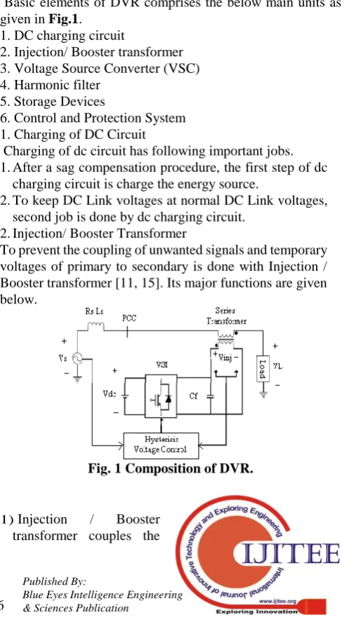
Basic elements of DVR comprises the below main units as
given in Fig.1.1. DC charging circuit
2. Injection/ Booster transformer 3. Voltage Source Converter (VSC) 4. Harmonic filter
5. Storage Devices
6. Control and Protection System 1.Charging of DC Circuit
Charging of dc circuit has following important jobs. 1.After a sag compensation procedure, the first step of dc
charging circuit is charge the energy source.
2.To keep DC Link voltages at normal DC Link voltages, second job is done by dc charging circuit.
2.Injection/ Booster Transformer
[image:1.595.305.549.394.837.2]To prevent the coupling of unwanted signals and temporary voltages of primary to secondary is done with Injection / Booster transformer [11, 15]. Its major functions are given below.
Fig. 1 Composition of DVR.
1) Injection / Booster transformer couples the
Reduction of Power Quality Issues in
Micro-Grid using GA Tuned PI Controller Based
DVR
inserted compensating voltages developed by voltage source converters to the voltage supply at the incoming side and connect the distribution system by DVR utilizing HV- winding of the transformer.
2) Isolation of the network load (VSC and control mechanism) is done with Injection / Booster transformer. 3.Voltage Source Converter (VSC)
VSC made of power electronics elements that comprises of a storage part and switching equipment that give a sine voltages from important magnitude, phase angle and frequency,. DVR uses, the VSC is utilized to briefly replacing input voltage supply or to develop a small quantity of the supply voltage which is not present [21].
The important intention of the storage equipment is give essential energy using a Link by DC for production of inserted voltages to VSC. Main types of energy storage equipments are capacitance and batteries [12], and also superconductive magnetic energy storage (SMES) [16, 18].
III. DVR FORMULAS
Load impedances Zth rely on load bus fault level. When
system voltage (Vth) decreases, DVR inserts a series voltage
VDVR to the insertion transformer, hence wanted magnitude
load voltage VL can be perpetuated as shown in Fig.2. The
inserted series voltages of the DVR in the form of VDVR=VL+ZthIL-Vth (1)
VL: The required voltage magnitude at the side
load
Zth: The impedance at the load side
IL: The current at the load side
Vth: The system voltage at the fault situation
The current at the load side IL is expressed as,
IL=
[P
L+jQ
L]/V
L(2)
Take the reference equation as VL which is
expressed as,
L L th thDVR
V
I
Z
V
V
0
(
)
(3)
α, β, δ are angles of VDVR, Zth, Vth respectively and θ
is load power angle.
The DVR complex power inserted can be expressed as,
* L DVR DVR
V
I
S
(4)
Fig. 2 DVR Equivalent Circuit.
IV. CONTROL STRATEGIES
Different types of control techniques suggested for DVR are Space Vector control for Voltage using PWM based suggested by Changjiang Zhan et al in [13 & 14]. Nagaraj et al [6] discussed the soft computing techniques based tuning algorithms for PID controller. These reviews tell that the transient response of the GA Tuned based PI tuning is predominant than that of PI types of Controllers. Mostafa I. Marei et al developed a latest method to find symmetrical parts for DVR controlling [19].
H. Ezoji et al developed hysteresis voltage control method for DVR [17]. To control the DVR, unipolar pulse width modulation utilizes the Hysteresis voltage control method. Fast controllability and simple application based voltage control based on hysteresis band has the largest demand over many types of control techniques.
1.PI Controller
The technique used as controller is very much important in order to limit voltage magnitude as a constant one at the place where a dedicated load beingconnected during system interferences. At load terminals, Root mean square (RMS) voltages are only checked by the control system, i.e., no requisite of kVAR power measurements. For simplicity and good response, the VSC switching approach deals with a sinusoidal PWM method. PWM techniques provide a better flexible alternative technique compared to the Fundamental Frequency Switching (FFS) techniques, because the custom power is comparatively a lower-power wanted one. Without affecting considerable switching losses, extortionate switching frequencies can be utilized have better efficiency of the converter.
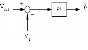
[image:2.595.348.499.552.638.2]Difference in the reference voltages and RMS value at terminal voltages measured called as the error signal which is the controller input. A PI Controller, such an error is controlled, the angle at output is δ, that is given to signal generator which is PWM as shown in Fig.3. By differentiating reference voltages with the calculated voltage (RMS) at the output side, an error signal is developed. Conventional controller type PI regulates the zero error which means that the rms load voltage is returned to voltage reference.
Fig. 3 PI Controller
.
V. HYSTERESIS VOLTAGE CONTROL
To
obtain good voltage at the load side and divert switching gate signals for inverters, voltage control by hysteresis is utilized. An error signal between voltages injected (Vinj) and a base voltage of DVR (Vref) which develops appropriate signals to be controlled is very much needed for hysteresis voltageFig. 4 Voltage Control with Hysteresis Band.
2.
GeneticAlgorithm (GA)
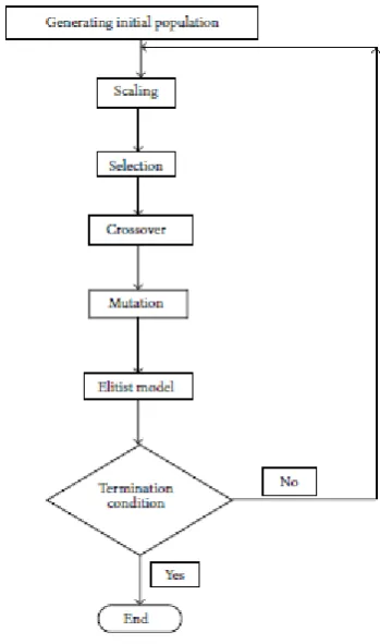
GA are optimized forage methods based on natural selection , natural genetics etc from biological systems in a computer algorithm to replicate evolution explained by Ge et al [9] and Melanie Mitchell [8]. They correlate survival of fittest with different structures that is yet to randomize information passing to constitute a search algorithm. In the early 1960s, John Holland and his colleagues created Genetic Algorithm in the University of Michigan. To give robust search in complex phases, genetic algorithms are theoretically and observationally been demonstrated. Its validity in –Function Optimization and Control Applications is well known. Genetic Algorithms (GA) define a general method for searching global minima or maxima in a bounded, quantized search space. GA can be normally given to approximately any effective one, because it needs only a method to evaluate fulfillment of its solution problem without any knowledge. To suit a particular application, GA is usually modified. An enhancement to the “traditional” genetic algorithm offers quick and best searches for GAs which cannot relate on average chromosome convergence. The “traditional” genetic algorithm consists of a fitness method, a selection criteria, crossover and mutation operators that are ruled by fixed probabilities. These steps together give a genetic loop as shown in Fig. 6. The average number of global searches and local in each generation is fixed, due to constant probabilities. Thus, the GA provides a fixed convergence rate and hence referred to as the fixed-rate GA.
Fig. 5 GA - Block Diagram
The simplest GA (Fig. 5) comprises of five paces:
(i) GA is started with an oddly generated population of M chromosomes, where M is the population size, n –chromosome length u.
(ii) For every chromosome u in the population, find the fitness value of function µ(u).
(iii) Redo up to M offspring’s is formed:
(iv) Restore present population with newly generated one.
(v) Then return to step (ii)
(1) PID Designing using Genetic Algorithm Genetic Algorithm can be used for PID controller gains tuning explained by Gao Jun–shan et al in order to assure optimality control criteria at general working situations [7]. The comparison between Genetics Algorithm and the conventional techniques is very essential to study. This will provide an idea why GA is better than the latter. From the more conventional search and optimization methods, Genetic algorithms are considerably dissimilar. The five important comparisons are:
1. Forage a population of points in parallel, not from a single
point is done with the help of Genetic algorithms.2. The direction of the search is pointed by the objective function and suitable proficiency levels. Hence Genetic algorithms do not need past datas or other additional knowledge.
3. Provide chance of transition rules, based on random rules for Genetic algorithms.
4. Working on the computing of a parameter set but not the parameter set itself by using Genetic algorithms.
[image:3.595.340.515.340.636.2]5. Number of potential remedies to a given query and the premier of the last is left up to the user may be provided with the help of Genetic algorithms.
[image:3.595.53.260.548.686.2]Table 1 Optimized gain values of PID controller
Gain Coefficient Kp Ki Kd
For population 5 0.3960 0.5320 0.6625
For population 10 0.3760 0.6121 0.0864
For population 15 0.8816 0.6691 0.4491
For population 20 0.9939 0.6888 0.2280
For population 25 0.4077 0.5404 0.3706
For population 30 0.3879 0.2354 0.2931
For population 35 0.4284 0.2618 0.7500
For population 40 0.7488 0.8702 0.2525
For population 45 0.2548 02142 0.6529
For population 50 0.0186 3.7281 0.9130
[image:4.595.60.278.66.237.2] [image:4.595.325.525.256.423.2] [image:4.595.320.526.263.606.2]After providing the above parameters to GA (as given in Table 2), the PID controller can fine-tuned and this system characteristics shall be enhanced with a population size of 40 is selected.
Table 2 GA Parameters
GA Terms Value/Method
Size of Population 40
Maximum no of
generations
4
Fitness Function /Performance Index
Mean Square error
Selection Algorithm Normalized Geometric Selection
Probability of
selection
0.05
Crossover Algorithm Arithmetic Crossover Number of crossover
points
3
Mutation Algorithm Uniform Mutation Mutation Probability 0.1
(2) Proposed Genetic Algorithm PID Controller Results
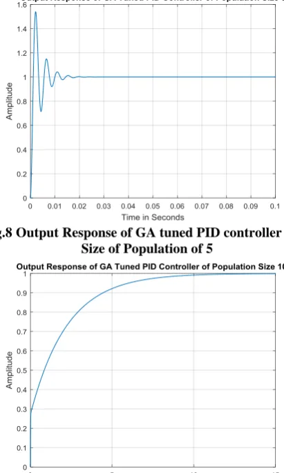
In this segment, simulation results of the suggested PID Controller parameters using GA tuned is given. PID controller gains based on GA is started with a size of population 5 and the output is studied. It is then repeated with population size increment of 5 from 5 up to 50. The GA tuned PID response will then be evaluated for the required design specifications. The much better response will then be selected as shown in Fig.11 to 14 and the optimized gain values are given in Table 1.
[image:4.595.63.268.292.516.2]From the calculated responses ie, by comparing the graphs shown in Fig. 7 and Fig. 8 to 11, Z-N tuned PID Method is not good compared to GA tuned PID. GA tuned PID Controller will have much good response, but has a very large settling and rise time.
Fig.7 Output Response of Z-N Tuned PID controller
Fig.8 Output Response of GA tuned PID controller with Size of Population of 5
[image:4.595.323.525.448.617.2]Fig 10 Output Response of PID controller with GA tuned with Size of Population of 25
Fig.11 Output Response of PID controller with GA tuned with Size of Population of of 40
VI. MATLAB SIMULATION RESULTS OF GA TUNED
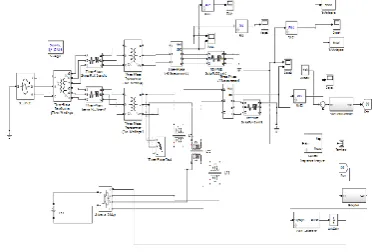
PID CONTROLLER BASED DVR Matlab result has been very important part in the power electronics application process. Main overall system without DVR Matlab model in Matlab/Simulink environment as given in Fig. 12. The four control strategies are presented to test the behavior of the DVR in different aspects .
The test system considered here to run the model for DVR with GA Tuned PI Controller is given Fig. 13. This system comprises of 13 kV, 50 Hz generation network, with two feeders at the transmission side with a three winding transformer interconnected in Star/Delta/Delta, (13/115/115) kV. Two distribution networks is fed by the particular transmission feeders with the help of two transformers in Delta/Star, (15/11) kV connection. The operation of DVR employed for voltage restitutes a fault is applied at point X at resistance 0.66 Ω for time period of 0.01s. DVR is simulated to be in execution only for the duration of the fault. Dc storage capacity amenity is 5 kV [22].
[image:5.595.65.269.56.222.2] [image:5.595.333.521.228.354.2]Fig. 12 Main diagram without DVR.
Fig. 13 Main diagram of DVR with GA Tuned PI Controller.
VII. SIMULATION OUTPUTS
A three phase fault is applying this network at point with a fault resistance of 0.66 Ω for a time period of 0.01 s with no DVR was the first simulation. Consider the situation as above, DVR is now inserted at the load side to compensate required voltage swell & sags developed due to three phase fault given is the second simulation
Fig. 14 shows load side voltages when the system works with PI DVR and a three phase fault is given to the network. When the GA Tuned PI DVR is in execution, the voltage disturbances are indemnify almost downright and the voltage at the subtle load point is controlled by normal situation and is shown in Fig. 15.
[image:5.595.348.526.563.705.2]Fig. 15 Voltage at the load with GA Tuned PI DVR
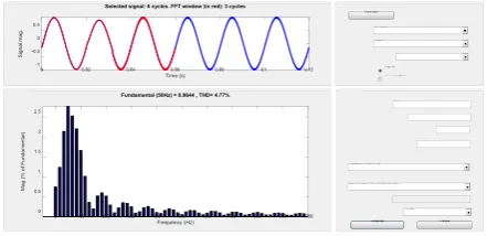
Fig. 16 THD Analysis for ZN Tuned PID Controlled DVR
Fig. 23 THD Analysis of Population size 40 for GA Tuned PID Controlled DVR
Table 3 Comparison of Control Algorithms Type of Control Method Total Harmonic
Distortion (THD) in %
PID Controller 5.96
GA Tuned PID Controller
4.78
The comparison table shown in Table 3 illustrating clearly the effectiveness of GA Tuned Based PI controller in various aspects.
The Total Harmonic Distortion (THD) for GA Tuned PI controller is good compared to ZN Tuned one.
VIII. SUMMARY
For keeping the voltage at load side constant, DVR is a newly suggested series type solid state device that inserts voltages into the system. At the point of common coupling, DVR is usually brought together with a distribution system between the supply and the critical load. Other features of DVR are
reduction of transients in voltage, line voltage harmonics compensation, and limitations due to fault current and then check the driving and unvarying DVR performance, other than voltage sags and swells compensation. The outputs of voltage graphs of DVR using PI Controller using GA Tuned with voltage sag & swell with three phase fault condition are analyzed. DVR with PI Controller using GA Tuned performs better than PI based DVR.
REFERENCES
1. Yun Wei Li, Frede Blaabjerg, D. Mahinda Vilathgamuwa, and Poh Chiang Loh, “Design and Comparison of High Performance Stationary-Frame Controllers for DVR Implementation” IEEE Transactions on Power Electronics, Vol. 22, No. 2, March 2007. 2. Ezhilarasan S., Balasubramanian G., DVR for Voltage Sag Mitigation
Using Pi with Fuzzy Logic Controller, International Journal of Engineering Research and Application, Vol. 3. 2013.
3. Y. Zhao. (Nov. 11, 2016). Electrical Power Systems Quality. Anusha, S., Karpagam, G., & Bhuvaneswarri, E. (2014). Comparison of tuning methods of PID controller. International J. of Management, Information Technology and Engineering, 3, 1-8.
4. R. Bayindir, E. Hossain, E. Kabalci, and R. Perez, ``A comprehensive study on micro grid technology,'' Int. J. Renew. Energy Res., vol. 4, no. 4, pp. 1094-1107, 2014.
5. Thaha H S, Ruben Deva Prakash, “Reduction of Power Quality Issues in Dispersed Generation & Smart Grids”, Journal of Advanced Research in Dynamical and Control Systems Vol. 9. Sp– 18 / 2017.
Jhapte, R., & Krishnan, K. Modelling Of Electric Arc Furnace And Control Algorithms Using Dstatcom With Fuzzy Logic For Improvement Of Power Quality.
6. Nagaraj B., Subha S., and Rampriya B “Tuning Algorithms for PID Controller Using Soft Computing Techniques”, IJCSNS International Journal of Computer Science and Network Security, Vol.8 No.4, pp.278-281, 2008.
7. [7] Gao Jun-shan, Mu Xiao-guang, and Yang Jia-xiang, “ PID controller based on GA and Neural network”, Electric Machines and Control, Vol 8, No 2, pp.108-111.
8. Melanie Mitchell. (1999), “An introduction to genetic algorithms”, Fifth printing, MIT Press.
Anusuya, V., & Kavitha, R. A New Hybrid Ant Based Genetic Algorithm–Fuzzy Shortest Path Problem.
9. Ge S.S., Lee T. H., and Zhu G. (1996), “Genetic algorithm tuning of Lyapunov-based controllers: An Application to a Single-Link flexible Robot System”, IEEE transaction on industrial electronics, Vol. 43, No.5.
10. Thaha H S, Ruben Deva Prakash, “Reduction of Power Quality Issues in Micro-Grid Using Fuzzy Logic Based DVR”, International Journal of Applied Engineering Research, ISSN 0973 -4562, Vol 13, Number 11 (2018) pp. 9746-9751.
Kanwar, P. S., & Sharma, R. Power Quality And Voltage Stability Of Transmission Line Using Statcom And Sssc.
11. Bingsen Wang, Giri Venkataramanan and Mahesh Illindala, “Operation and Control of a Dynamic Voltage Restorer Using Transformer Coupled H-Bridge Converters”, IEEE Transactions on Power Electronics, Vol. 21, No. 4, July 2006.
12. Bingsen Wang and Giri Venkataramanan, “Dynamic Voltage Restorer Utilizing a Matrix Converter and Flywheel Energy Storage” IEEE Transactions on Industry Applications, Vol. 45, No. 1, January/February 2009.
13. Changjiang Zhan, Vigna Kumaran Ramachandaramurthy, Atputharajah Arulampalam, Chris Fitzer,Stylianos Kromlidis, Mike Barnes and Nicholas Jenkins, “Dynamic Voltage Restorer Based on Voltage-Space-Vector PWM Control” IEEE Transactions on Industry Applications, Vol. 37, No. 6, November/December 2001.
[image:6.595.58.284.383.490.2]14. Changjiang Zhan, Atputharajah Arulampalam and Nicholas Jenkins, “Four-Wire Dynamic Voltage Restorer Based on a Three-Dimensional Voltage Space Vector PWM Algorithm”, IEEE Transactions on Power Electronics, Vol. 18, No. 4, July 2003.
15. Chris Fitzer, Atputharajah Arulampalam, Mike Barnes and Rainer Zurowski, “Mitigation of Saturation in Dynamic Voltage Restorer Connection Transformers“,IEEE Transactions on power electronics, vol. 17, no. 6, november 2002.
16. Hirofumi akagi, Yoshihira kanazawa and Akira nabae, “Instantaneous Reactive Power Compensators Comprising Switching Devices without Energy Storage Components”, IEEE Transactions on industry applications, vol. ia-20, no. 3, may/june 1984.
17. H. Ezoji, M.Fazlali, A.Ghatresamani and M.Nopour, “A Novel Adaptive Hysteresis Band Voltage Controller for Dynamic Voltage Restorer”.European Journal of Scientific Research ISSN 1450-216X Vol.37 No.2 (2009), pp.240-253.
Park, S. M., & Park, S. Y. (2014). Versatile control of unidirectional AC–DC boost converters for power quality mitigation. IEEE Transactions on Power Electronics, 30(9), 4738-4749.
18. Jing Shi, Yuejin Tang, Kai Yang, Lei Chen, Li Ren, Jingdong Li and Shijie Cheng,“SMES Based Dynamic Voltage Restorer for Voltage Fluctuations Compensation”, IEEE Transactions on Applied Superconductivity, Vol. 20, No. 3, June 2010.
19. Mostafa I. Marei, Ehab F. El-Saadany, and Magdy M. A. Salama, “A New Approach to Control DVR Based on Symmetrical Components Estimation” IEEE Transactions on Power Delivery, Vol. 22, No. 4, October 2007.
20. Pedro Roncero-Sanchez, Enrique Acha, Jose Enrique Ortega- Calderon, Vicente Feliu, and Aurelio García-Cerrada. “A Versatile Control Scheme for a Dynamic Voltage Restorer for Power-Quality Improvement” IEEE Transactions on Power Delivery, Vol. 24, No. 1, January 2009.
21. S.R. Naidu D.A. Fernandes, “Dynamic voltage restorer based on a four-leg voltage source converter” IET Gener. Transm. Distrib., 2009, Vol. 3, Iss. 5, pp. 437–447.
22. Teke K. Bayindir and M. Tumay, “Fast sag/swell detection method for fuzzy logic controlled Dynamic Voltage Restorer” IET Gener. Transm. Distrib., 2010, Vol. 4, Issue. 1, pp. 1–12.
AUTHORSPROFILE
Thaha H.S received the B.Tech degree in Electrical & Electronics Engineering from the University of Kerala, India in 2009, M.E degree in Power Systems Engineering from the Anna University, Chennai, Tamilnadu, India in 2013. He is currently pursuing Ph.D degree in the area of Power Quality, from Sathyabama University, Chennai, Tamilnadu, India. His current research interest includes the application of soft computing techniques in power system, renewable energy systems, power quality, micro grid and composite micro grid technologies.