Materials Science and Engineering Publications Materials Science and Engineering
12-2000
Advances in deformation processed gold
composites
Vladimir Gantovnik
Iowa State University
Alan M. Russell
Iowa State University, [email protected]
L. Scott Chumbley
Iowa State University, [email protected]
Kageeporn Wongpreedee
Iowa State University
Dennis Field
Iowa State University
Follow this and additional works at:http://lib.dr.iastate.edu/mse_pubs Part of theMetallurgy Commons
The complete bibliographic information for this item can be found athttp://lib.dr.iastate.edu/ mse_pubs/39. For information on how to cite this item, please visithttp://lib.dr.iastate.edu/ howtocite.html.
Advances in deformation processed gold composites
Abstract
Conventional metallic composites are comprised of a metal matrix with a ceramic second phase. In recent years, composites have been developed in which both the matrix and the reinforcing phase are ductile metals. In 1998 a 90 vol%Au – 10 vol% Ag metal-metal composite wire was produced and found to possess both high tensile strength (550 MPa) and low electrical resistivity (2.56 m ohm-cm). In that composite, the silver reinforcing phase consisted of sub-micron diameter filaments parallel to the wire axis. This article describes the microstructures, mechanical properties, and electrical resistivity of three gold matrix composites in which the reinforcing phases are 7 vol% Ag, 14 vol% Ag, and 7 vol%Pt. These composites were drawn to diameters as small as 60 microns. Results from wedge bonding trials with these composite wires are also reported.
Keywords
Ames Laboratory
Disciplines
Materials Science and Engineering | Metallurgy
Comments
Advances in Deformation Processed Gold
Composites
Vladimir Gantovnik, Alan Russell, Scott Chumbley,
Kageeporn Wongpreedee and Dennis Field
Ames Laboratory of Iowa State University, Ames, IA, 50011, USAE-mail: [email protected]
Received: 7 September 2000
Conventional metallic composites are comprised of a metal matrix with a ceramic second phase. In recent years, composites have been developed in which both the matrix and the reinforcing phase are ductile metals. In 1998 a 90 vol%Au – 10 vol% Ag metal-metal composite wire was produced and found to possess both high tensile strength (550 MPa) and low electrical resistivity (2.56 m ohm-cm). In that composite, the silver reinforcing phase consisted of sub-micron diameter filaments parallel to the wire axis. This article describes the microstructures, mechanical properties, and electrical resistivity of three gold matrix composites in which the reinforcing phases are 7 vol% Ag, 14 vol% Ag, and 7 vol%Pt. These composites were drawn to diameters as small as 60 microns. Results from wedge bonding trials with these composite wires are also reported.
High strength, high electrical conductivity metal-metal composites can be produced with a gold matrix. These composites are potentially useful in assembly of electronic semi-conductor devices or in other applications requiring high hardness and high conductivity. Assembly operations for most electronic circuits require ball bonding and wedge bonding of interconnect wire to connect microprocessors and related devices to other components on the circuit board. Various low alloy compositions of nearly pure gold wires, typically 20 to 50 m in diameter, are used for such interconnects. The ideal interconnect wire would possess high electrical conductivity, high strength, ease of manufacture into long lengths of wire (typically 10 km per spool) with near zero defects, and good performance in both ball bonding and wedge bonding procedures. The minimum wire size in widespread use today is 20 m diameter. Although there would be engineering advantages to using still finer wire, the relatively low strengths of the gold alloys in use today make finer wire difficult to use.
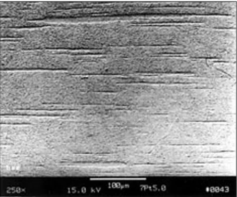
The gold composite wires being developed in this research have strength superior to that of the gold interconnect wires now in use. The composite microstructure shown in Figure 1 consists of a pure gold matrix containing filaments of pure silver or pure platinum lying parallel to the wire axis. The second
phase metal filaments block dislocation motion in the gold matrix, giving the wire high strength. These composites are called deformation-processed metal metal composites (DMMC’s) because extensive plastic deformation by wire drawing is used to reduce the thickness and spacing of the reinforcing phase. As deformation reduces the distance between such matrix-filament interfaces, the composite’s strength increases. From an electrical perspective, the composite wire can be considered to be a bundle of pure gold and pure silver or platinum fibres in parallel. Since there are essentially no precipitate particles or solid solution atoms in the gold to scatter electrons, the electrical resistivity is only modestly higher than that of pure gold.
In 1998, the first effort was made to develop a gold-matrix DMMC with high strength and low resistivity (1). The authors reported on a 90 vol%Au-10 vol%Ag DMMC that was produced by deformation processing a cold isostatically pressed powder compact. The Au-Ag specimen studied had an ultimate tensile strength of 550 MPa and an electrical resistivity 8% higher than that of pure gold at a deformation processing true strain of 5.6. The present investigation was carried out to examine several poorly understood aspects of processing, structure evaluation, and strengthening in Au-Ag DMMC’s and to determine whether a Au-Pt DMMC could be produced.
EXPERIMENTAL
Details of material preparation methods have been reported previously (1). Au-Ag compacts containing 7% and 14% Ag (volume % is used throughout this report) and a Au-Pt compact containing 7% Pt were prepared by mixing and cold isostatically pressing (172 MPa) pure elemental gold, silver, and platinum powders. For consolidation, the cold isostatically pressed compacts were sealed in annealed copper cans before deformation processing. The true strain of the specimens was calculated using Equation (1):
d0
= 2ln ––– (1)
df
where, is the true strain, d0 is the original diameter, and df is the final diameter. From cylindrical compacts, wires were produced by rotary swaging to strain = 4.1 and drawing to = 5.8. The copper sheath was removed with nitric acid at = 5.8, and the bare wires were then drawn to = 9.3 for all three compositions. The Au-7%Ag DMMC was drawn further to 60 micron diameter wire ( = 11.3).
Mechanical properties of drawn wires were determined for larger diameter wires by tensile testing at a strain rate of 1.3 mm/min. Wires smaller than 0.5mm in diameter were too small to allow tensile testing.
Microstructure was examined using a field emission scanning electron microscope (SEM) in the back-scattered electron mode on samples prepared by standard metallographic techniques. In one case, the microstructure of a specimen thinned by ion milling was examined by transmission electron microscopy (TEM). Quantitative measurements of microstructures were determined from the micrographs using standard stereographic intercept procedures (2). The chemical composition was locally determined by use of an energy-dispersive x-ray spectrometry system (EDS). Four-point resistance of samples was measured using a micro-ohmmeter operating in the pulse mode to eliminate thermal EMFs. The samples were in the form of drawn wires of uniform cross sectional area. Small grooves were machined into each sample for the application of voltage sense probes. Source current probes were clipped to the ends of the samples. Four resistance measurements were obtained and averaged for each sample.
RESULTS AND DISCUSSION
During mechanical processing (swaging and drawing), the initial minor phase equi-axed particles gradually
transformed into long thin filaments. The second phase particles are only moderately elongated during swaging but become fine-scale, highly elongated filaments during drawing. Figure 1 shows scanning electron micrographs of longitudinal and transverse sections of the Au-7%Pt composite after swaging and subsequent drawing to = 5.0.
[image:4.595.310.545.259.455.2]The morphology of the phase structure of the wire appears to be stable against both diffusion homogenization and spheroidization effects at room temperature. Some specimens have been stored for as long as two years with no observable change in microstructure. However, at elevated temperatures (eg
Figure 1bSEM, BSE micrograph of a transverse section of the Au-7%Pt DMMC wire, =5.0. The
[image:4.595.307.546.488.698.2]magnification in this image is considerably higher than in Figure 1a
130 Gold Bulletin2000, 33(4)
[image:5.595.305.546.399.722.2]diameter in the Au-7%Ag composite was 2.0 m. A plot of the gold matrix spacing and platinum filament thickness versus deformation strain is given in Figure 2.
On the basis of microstructural data, the dimensions of the composite phases with increasing wire deformation are described by Equations (2) and (3):
dAu() = dAu0– kAuln() (2) dPt() = dPt0– kPtln() (3) where, dAu() is the gold matrix spacing, dPt() is the Pt filaments thickness for a deformation strain . The experimental results can be fitted in the range 1< < 6 by dAu0= 158300 nm, kAu= 66741 nm, dPt0= 11821 nm, kPt= 4941 nm.
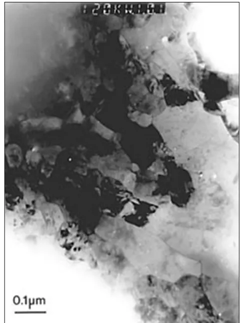
At large values of , the minor phase filaments become very small, and it is difficult to obtain accurate phase size and spacing data from SEM microscopic examination because the smallest filaments may fall below the resolution limit of the microscope. The best method for measuring the very fine filament spacing 400°C) the two phases will intermix by diffusion and
degenerate into the simple solid solution predicted by the equilibrium phase diagrams (1). No observable diffusion barrier has been seen at the phase interfaces. The silver and platinum powder particles may have had a thin initial coating of oxide and adsorbed gas, but since the surface area of each particle increases approximately fifty-fold during deformation, such coatings are presumably no longer continuous at high
levels.
Although the back-scattered electron atomic number contrast is weak between Au (Z = 79) and Pt (Z = 78), the long filaments of platinum in the gold matrix are clearly visible from their relief on the polished metallographic surface. This microstructure is the desired outcome of the deformation processing. Many DMMC’s produced with an FCC matrix and a BCC second phase (eg Cu-Nb) develop a convoluted ribbon shape in the minor phase due to texturing effects that limit strain in the second phase to plane strain (3 - 8). This is not seen in the FCC-FCC Au-Pt and Au-Ag DMMC’s, since the FCC structure of the minor phase has multiple slip systems, and therefore the plane straining mode seen in BCC metals is absent in Au-Ag and Au-Pt DMMC’s. The filaments in these DMMC’s changed during deformation processing from their initial shape of approximately equiaxed particles to filaments that are roughly cylindrical in shape.
The spacing between the filaments is an important factor in the strength of a DMMC, since the filaments act as barriers to dislocation motion. After deformation to = 5.8, the average filament diameter in the Au-7%Pt composite was 3.1 m, and the average filament
0 2 0 4 0 6 0 8 0 1 0 0
0 1 2 3 4 5 6
Au-7Ag Ag filament thickness Au-7Pt Pt filament thickness Au-7Ag Au matrix spacing
F
ilament Thickness
or
M
atrix S
pacing (micr
ons)
True Strain
[image:5.595.54.285.533.697.2]Au-7Pt Au matrix spacing
Figure 2Gold matrix spacing and thickness of silver and platinum filaments in DMMC’s as a function of the amount of imposed work (swaging and wire drawing)
and thicknesses of these heavily drawn composite wires is TEM imaging. A TEM image of the Au-7%Pt DMMC at = 9.3 (wire diameter 190 mm) is shown in Figure 3. Since TEM and SEM phase size and thickness measurements are seldom directly comparable, Figure 2 does not include data from the TEM specimen.
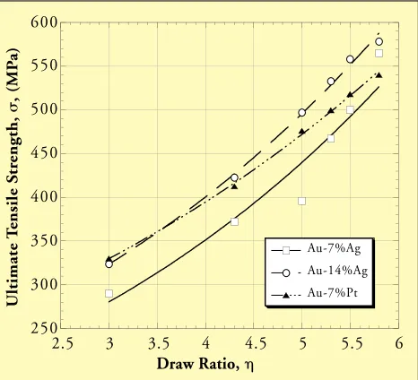
The result of the mechanical tests performed on Au-based DMMC’s show large increases in strength as deformation processing progresses. As would be expected, deformation processing substantially increased the ultimate tensile strength, UTS of both Au-Ag and Au-Pt composites. A comparison of the strength of these composites to that of pure gold shows a quadrupling of ultimate tensile strength at = 5.8, which is the highest value for which tensile testing was possible. Figure 4 shows the effect of true strain on the ultimate tensile strength for Au-Ag and Au-Pt composites.
The curves show no sign of leveling off at high true strains as does the strength of pure gold. This observation suggests that additional strengthening would result at larger strain, as is typically observed in other DMMC’s (7). This behaviour is similar to the ultimate tensile strength increase seen in axisymmetrically deformed Cu-20%Nb DMMC over the same true strain range (9, 10). The reduction in filament thickness and spacing is thought to be the primary factor causing the increase in ultimate tensile strength and the modest decrease in ductility observed in Cu-20%Nb specimens deformation processed to
high true strain. Some investigators have reported that in Cu-Nb DMMC’s at large deformations, the dislocation density appears to continuously increase while the filament thickness continually decreases (11 -17). Others have reported quite different findings, observing that dislocation density first increases as true strain increases, but then the dislocation density appears to reach a plateau, and no further increase is observed as true strain increases to the highest levels. Some reports have even stated that dislocation densities appear to decline at the highest true strains (18, 19). In general, the increased strengthening of all DMMC specimens is believed to result from the effectiveness of the minor phase interfaces as barriers to the motion of matrix dislocations (7). As phase spacing in the gold matrix becomes very small (ieless than about 100 nm), the small volume of gold between minor phases also makes it ‘energetically costly’ to operate Frank-Read dislocation sources, which may also contribute to the high strength. While investigators continue to debate some aspects of the very high strengths seen in DMMC’s, there is general agreement that DMMC’s become progressively harder and less ductile as deformation progresses. The only upper limit to ultimate tensile strength observed in these materials appears to be the theoretical limit of shear strength (t) (20):
ttheoretical= G (4)30
Where G is the material’s shear modulus. In the case of gold, where the shear modulus is 27.5 GPa, the theoretical maximum shear strength would be estimated at 920 MPa, which by Schmid’s Law corresponds to a theoretical strength of approximately 1800 MPa.
Electrical resistivity measurements were made for 0.55 mm diameter wires ( = 6.3). The tests of the electrical resistivity of the Au-7%Ag wire show a room temperature resistivity of 2.418 ohm-cm (pure gold is 2.35 ohm-cm). Since the composite consists of pure silver filaments in a pure continuous gold matrix, such low resistivity is not surprising. The filaments are oriented parallel to the wire axis; the second phase presents a minimal scattering cross section to current. In conventional alloys, increasing strength causes a large rise in resistivity. By comparison, typical solid solution alloys of gold having strength comparable to that of the gold matrix deformation processed composite have electrical resistivities that are many times higher than that of pure gold, ranging from 10 250 300 350 400 450 500 550 600
2.5 3 3.5 4 4.5 5 5.5 6
[image:6.595.55.288.498.710.2]Au-7%Ag Au-14%Ag Au-7%Pt U ltimate T ensile S tr ength, , (MP a) Draw Ratio,
132 Gold Bulletin2000, 33(4)
to 40 ohm-cm at 295 K. Figure 5 shows the dependence of the resistivity at 295 K of Au-Ag DMMC’s as a function of the deformation.
MICROSTRUCTURE-STRENGTH
CORRELATION
The data from Figures 2 and 4 are re-plotted in Figure 6 on logarithmic coordinates to show the dependence of strength on the mean values for filament thicknesses in the gold matrix DMMC’s. The strength of Au-Ag and Au-Pt composites show a common correlation with filament spacing, ie the mean free path for dislocation motion in gold. Filament spacing and filament thickness tend to be reduced in proportion to one another as deformation progresses, so a similar plot could be made for strength versus filament spacing. Current thinking in the DMMC community holds that it is the matrix spacing that primarily controls the strength of DMMC’s. If this is so, the primary function of the minor phase filaments is to provide closely spaced barriers to dislocation glide in gold. These conclusions are in accord with earlier observations in other DMMC systems where the dislocation densities in minor phase filaments decreased drastically as the matrix composite strength rapidly increased at the larger draw ratios (18, 19). The slope of the lines in Figure 6 is –0.46, which is essentially the Hall-Petch slope of –0.50.
POTENTIAL APPLICATIONS
The combination of high strength, good ductility, and low electrical resistivity makes these gold DMMC’s potentially useful for interconnect wire, testing probes, switch contacts, and similar applications. Trial wedge bonds have been produced with 60 μm diameter Au-7Ag DMMC wire (Figure 7).
2.4 2.5 2.6 2.7 2.8 2.9 3
6 6.5 7 7.5 8 8.5 9 9.5
Au-7%Ag Au-14%Ag Au-7%Pt
True Strain
R
esistivity
,
, (
[image:7.595.53.289.77.300.2]ohm-cm)
Figure 5Electrical resistivity of Au-Ag and Au-Pt DMMCs as a function of the amount of imposed deformation
Au-7 vol.% Pt (exper.) Au-7 vol.% Pt (theor.) Au-7 vol.% Ag (exper.) Au-7 vol.% Ag (theor.)
F
ilament thickness t,
m
Ultimate tensile strength , MPa
10 9 8 7 6 5
4
3
2
1
[image:7.595.312.546.78.301.2]300 400 500 600 700 800 900
Figure 6 Gold matrix DMMC spacing and filament thickness in Au-7%Pt plotted against the natural logarithm of the deformation true strain. Dashed lines are extrapolations
[image:7.595.308.546.479.723.2]The wire’s high hardness requires substantially greater force than is needed to wedge bond conventional interconnect alloys. Forces high enough to damage or separate the pad from its substrate were sometimes required to form a successful bond. Presumably, this problem would be less severe for smaller diameter wire. Pull tests performed on the wedge bonds were attempted, but the apparatus used had a maximum load of 100 grams, and the wedge bonds did not fail at this load. Ball bonding trials and electromigration studies following prolonged exposure to high current densities are in progress.
In a ball bond, these gold DMMC’s will become solid solution alloys in the fusion zone and in the heat-affected zone (HAZ). Thus the strength and resistivity of the material at the ball bond will differ from those of the DMMC. For the case of gold containing 7% silver in solid solution, electrical resistivity is about 5 μohm-cm. The cross sectional area of the ball is, of course, much larger than the cross sectional area of the wire; however, the HAZ just above the ball will be a solid solution alloy with the same cross sectional area as the wire and may tend to become a ‘hot spot’ when current densities are high. The possible advantage to use of a Au-Pt DMMC lies in the fact that the diffusion coefficients for Pt diffusing through gold are two orders of magnitude lower than the diffusion coefficients for silver diffusion through gold. Thus, solid solution formation in the HAZ of a Au-Pt ball bond might be expected to be more limited.
Although these DMMC wires have an appealing combination of mechanical and electrical properties, several questions remain to be resolved before actual use in interconnect applications can be considered. These factors include:
1 Ball bonding performance: surface tension or other factors acting on the liquid ball may affect ball bonding behaviour.
2 Electromigration : the second element might prove to be quite mobile in the presence of the large DC current densities (105 amperes/cm2 and higher) common in interconnect wire applications. Silver in particular is often a highly mobile atom under these circumstances. A study of electromigration in these composite wires began in these laboratories in late 2000.
3 Manufacturing difficulties in producing defect-free wire: for practical use, the wire must draw well to permit reliable manufacture of 10,000 m spools of wire. If the material breaks during drawing, even if such breaks occur relatively infrequently, wire production costs become prohibitive.
The advantages of using DMMC interconnects could be substantial. Their higher strengths (and in the case of the gold-platinum composite, higher elastic modulus) would permit several improvements in interconnect design. The interconnect wires could presumably be made smaller in diameter, because their higher strength would permit the same pull test results one obtains with the larger diameter, weaker wire used today. This in turn might permit tighter packing (more interconnects per mm of perimeter space around the chip) and/or longer pitch (longer span between the lead frame and the chip), as well as more robust connections for applications involving high vibration or g-loading.
CONCLUSIONS
Wires of Au-7%Ag, Au-14%Ag and Au-7%Pt composites were formed by powder metallurgy techniques. After extensive cold reduction, the minor phase powder particles were aligned in the deformation direction. With increasing deformation, the strength of gold matrix DMMC’s increases sharply; unfortunately, tensile testing was not possible at the highest levels of deformation due to the small diameter of the specimens. Strengthening in gold matrix composites appears to arise from the minor phase filaments acting as barriers to dislocation motion. The large plastic strains developed during mechanical processing result in a substantial reduction in the spacing of these minor phase filaments, and the observed dependence of strengthening on this spacing is in reasonably close accord with the Hall-Petch relationship.