Chapter 11
Developing J2ME Mobility
Applications
The NetBeans Mobility Pack can simplify many aspects of your MIDP development process. It includes, among other things, MIDP Visual Designer for managing the flow and content of your application screens, an integrated device fragmentation solution with editor support, and an end-to-end build process that can even include deployment of the application to a remote server.
This chapter covers a range of the Mobility Pack functionality and should give you a better understanding of how you can use many of its features. Projects created for NetBeans Mobility Pack share many qualities with general Java projects. You should, therefore, read through the earlier sections of this book, as this section primarily describes the differences between general and Mobility project types.
Downloading and Installing the Mobility Pack
The standard NetBeans IDE 4.1 download does not include support for developing mobile applications. You need to download the Mobility Pack separately and use its “add-on” installer to integrate the Mobility Pack functionality with the NetBeans IDE installation you already have on your system.
For NetBeans IDE 4.1, you should be able to find the Mobility Pack on the same download as the IDE.
Once you have downloaded the installer, launch it (in the same way that you launched the NetBeans IDE installer) and complete the wizard. The wizard will help you identify the installation of NetBeans IDE to build on.
Mobility Primer
NetBeans Mobility Pack makes it easy for all programmers to start
development for J2ME applications quickly, even if you’ve had only J2SE programming experience.
If you are trying out mobile programming for the first time, you can just think of J2ME as having a more limited version of the J2SE API and let NetBeans Mobility Pack take care of the foreign J2ME issues. Though there are more differences than just a smaller API, it’s not necessary to know all the intricacies before producing a working mobile application. To help you get started, here are some terms that are used throughout this document:
PDAs, but J2ME is also used on other embedded systems. A
configuration, a profile, and optional packages are what compose a J2ME platform.
[lb] CLDC —Connected Limited Device Configuration is a J2ME configuration that is currently most often used on mobile phones. It contains a runtime environment and a core API that are appropriate for the limited processor speed and memory size of mobile devices.
[lb] MIDP —Mobile Information Device Profile is the set of APIs that provides higher-level functionality required by mobile applications, such as
displayable components (“screens”) and network communication.
[lb] MIDlet —A class required by all MIDP applications. It acts as the interface between the application and the device on which it is running. A MIDlet is similar to a main class in a J2SE project.
[lb] Preverification—When building an application that runs with CLDC, all compiled classes must be preverified. Preverification is a process that adds annotations used by the CLDC JVM to a class file’s bytecode. The preverification process also ensures that the class contains only code that will run on its CLDC version.
[lb] Device fragmentation —Term used for the variations between mobile platforms that prevent a single application from automatically running optimally on all phones. These differences can be physical (screen size, screen color depth, available memory, and so on) or software related (available APIs, CLDC/MIDP version, and so on).
[lb] Preprocessor—Though preprocessor is not a J2ME-specific term, NetBeans Mobility Pack ships with a preprocessor that is used as part of its device fragmentation solution. The preprocessor is an Ant task that runs before files are compiled. It looks for special Java comment tags within the file and adds or removes line comments based on these tags. [lb] Obfuscation—A process that makes class files difficult to
reverse-engineer. This is usually accomplished by, at least, replacing names of packages, classes, methods, and fields with short identifiers. This has the result of decreasing the size of your application and, therefore, is an important aspect of the mobile application build process.
If you’re interested in learning more, countless online and offline resources are available. A good place to start looking is
http://java.sun.com/j2me/.
Setting Up Mobility Projects
Creating a new project is your first step in developing with NetBeans Mobility Pack. The IDE does the following upon project creation:
[lb] Create a source tree optionally containing a simple MIDlet.
[lb] Select an appropriate emulator platform for your project. Normally, the bundled J2ME Wireless Toolkit platform is selected.
debugging, and building Javadoc.
Creating a Project from Scratch
The process of creating a project from scratch is nearly identical to how it is done with general Java projects:1. Choose File | New Project.
2. In the Categories tree, select the Mobile folder. 3. Select Mobile Application or Mobile Class Library
The Mobile Application template provides an option to generate an example MIDlet automatically. The Mobile Class Library does not generate any classes for you.
The MIDP 1.0 UI, the MIDP 2.0 UI, and the Bluetooth examples use the Visual Designer.4. Click Next.
5. Optionally, fill in the following fields in the Name and Location panel of the wizard:
Project Name. The name by which the project is referred to in the IDE’s user interface.
Project Location. The location of the project on your system.
The resulting Project Folder field shows the root project directory that contains folders for your sources, build and properties files, compiled classes, and so on. 6. Optionally, deselect the Set As Main Project checkbox if you have another
project open that you want associated with the IDE’s main project commands (such as Build Main Project).
7. Optionally, if you selected Mobile Application project, you may deselect the Create Hello MIDlet checkbox to avoid generating an example MIDlet. Otherwise, a small sample MIDlet is created that uses the Visual Designer. 8. Choose the emulator platform you would like your project to use by default. This
setting controls your project’s classpath as well as which emulator and device are launched when you run your project.
Note that you can change this setting once the project has been created. 9. Click Finish.
Importing a Project
J2ME supports automatic imports from existing J2ME Wireless Toolkit projects, Sun Java Studio Mobility projects, and projects consisting of stand-alone MIDP sources. When you import projects, the sources remain in their current locations.
NetBeans IDE Tip
Unlike with general Java projects, only a single source root is supported for Mobility projects. If the project you are importing has multiple source roots, you have to create one project for each source root and then make dependencies between the projects. This is explained further in
To create a new NetBeans project from a Sun Java Studio Mobility project or stand-alone sources:
1. Choose File | New Project.
2. In the Categories tree, select the Mobile folder.
3. Select Import Mobility Studio Project or Mobile Project from Existing MIDP Sources, and click Next.
4. In the Imported Sources Location field, enter the folder that contains the default package of your sources (the folder might be called src).
5. In the Imported Jad/Manifest Location field, enter the folder that contains the application’s JAD file. You can leave this field blank if your project does not have a JAD file.
6. Click Next.
7. Optionally, edit the following fields in the Name and Location panel of the wizard:
Project Name. The name by which the project is referred to in the IDE’s user interface.
Project Location. The location for the new project.
8. Optionally, deselect the Set As Main Project checkbox if you have another project open that you want associated with the IDE’s main project commands (such as Build Main Project).
9. Click Next.
10. Configure the project’s default emulator platform. 11. Click Finish.
To create a new NetBeans project from a J2ME Wireless Toolkit project: 1. Choose File | New Project.
2. In the Categories tree, select the Mobile folder. 3. Select Import Wireless Toolkit Project and click Next.
4. On the Specify WTK Project page of the wizard (shown in Figure 11-1, specify the location of your Wireless Toolkit installation directory that contains the project you would like to install.
Figure 11-1
New Project Wizard, Specify WTK Project page
5. A list of all projects contained in the installation directory is displayed. Highlight the project you would like to import.
NetBeans IDE Tip
Two projects that use the same source root should not be open
concurrently within the IDE. Though the IDE takes steps to prevent this situation, the projects will become unstable should it occur.
Configuration vs. Configuration
One naming conflict that can cause confusion in this text is that between the NetBeans concept of project configuration and the J2ME concept of device configuration. Because this text focuses on covering the NetBeans IDE, the unmodified term configuration will henceforth be referring to project configurations.
Physical Structure of Mobile Projects
You can examine the physical structure of your Mobile project using the Files window. This window is located, by default, next to the Projects window or accessible via Window | Files in the main menu.
When you create a Mobile project, the IDE creates the same directories and files as those that are created for general Java projects, except that a separate test directory is not created. Tests, if generated, are placed in the same packages as the classes they are testing.
The build and dist folders, created the first time you build the project, are slightly different due to the more complicated nature of the MIDP build process. The following directories are created under build:
[lb] compiled folder, which contains all compiled classes.
[lb] preprocessed folder, which holds preprocessed versions of your source files. The files contained here are different from the original sources only if you are using configurations.
These are the class files that are packaged in your project’s distribution JAR file. These files are maintained both to increase the speed of the build process and to give you information you can use to isolate where in the build process bugs may have been introduced into your application.
NetBeans IDE Tip
The NetBeans build process follows Ant standards for management of temporary build classes. This means that only source files with a more recent timestamp than that of the class files in the build directories are automatically rebuilt when the Build command is run. Also, deleting a source file from the project doesnot automatically delete the associated class files from the build directories. Therefore, it is important to clean and rebuild the project after a source file has been removed from the project.
The dist folder contains your project’s distribution JAR file and JAD file.
Using Mobility File Templates
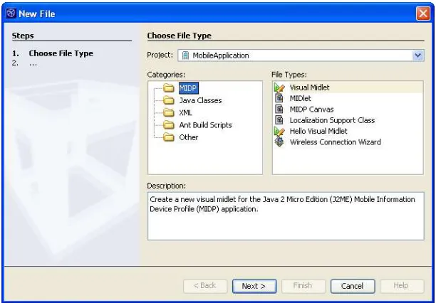
[image:6.612.153.459.382.595.2]The process of creating files in Mobility projects is identical to that of creating files in general Java projects. Templates for creating MIDP classes can be found under the top-level MIDP category in the New File Wizard, as shown in Figure 11-2. You can open the New File wizard by choosing File | New File.
Figure 11-2
New File Wizard, MIDP templates
MIDP Canvas
To create a MIPDCanvas:
MIDP Class Name. The name for the new class.
Package. The package in which the new class is located.
The resulting Created File field shows the full path location of your new class. 3. Click Finish.
MIDlet
The wizard for creating MIDlet file types differs slightly in that it also collects information that is used in the application’s JAD file.
1. Select one of the MIDlet file types in the File Types list and click Next. 2. Optionally, modify the following fields in the Name and Location panel of the
wizard:
MIDlet Name. This is the value that is shown in the list of MIDlets displayed when starting the application. It can be different from the MIDlet’s class name. MIDP Class Name. The name for the new MIDlet class.
MIDlet Icon. The location of this MIDlet’s icon. The combo box contains all . png files located in your project.
Package. The package in which the new MIDlet is located.
The resulting Created File field shows the full path location of your new class. 3. Click Finish.
NetBeans IDE Tip
All MIDlets that you add to the project are automatically added to the project’s application descriptor.
Localization and Support Class
This is an advanced template that uses configurations; therefore, it is described in Localizing Applications later in this chapter.
Configuring the Project’s Classpath
Like most project settings, the classpath used to compile Mobility projects is managed in the Project Properties dialog box. Two panels in particular control the classpath: the Libraries & Resources panel and the Platform panel. In addition to compilation, code completion is controlled by these settings.
Changing the Project’s Emulator Platform
The selected emulator platform is used to determine which vendor-supplied libraries are to be used for project compilation. By default, your project is configured to use the latest version of the J2ME Wireless Toolkit. You can modify this using the Platform panel of the Project Properties dialog box:1. Right-click your project in theProjects window and select Properties.
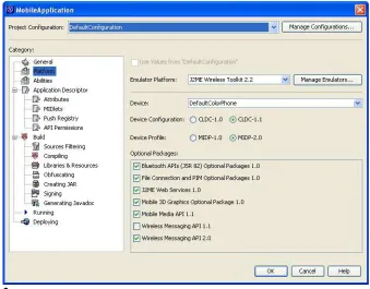
Figure 11-3
Mobile Application Project Properties dialog box, Platform panel
3. Optionally, modify any of the following fields to change which emulator libraries are used to build and run the project:
Emulator Platform. The installed emulator platform you would like to use. This controls which values are available for all following fields.
Device. Selects which device skin to use when launching the application. Device Configuration. Determines the Device Configuration. This setting affects your classpath.
Device Profile. Determines the Device Profile. This setting affects your classpath.
Optional APIs. Select or deselect any number of Optional APIs. Again, this setting affects your project’s classpath.
NetBeans IDE Tip
Sometimes, one device profile or device configuration is disabled when a given emulator platform is selected. This is a result of that emulator platform’s response to a Unified Emulator Interface (UEI) query regarding its profile and configuration abilities. You can still develop an application for the disabled configuration or profile using the selected platform (for example, developing a MIDP-1.0 profile with the WTK2.0 emulator platform).
First, ensure that you do not use any invalid code for the desired profile or configuration; then add a Configuration or MicroEdition-Profile attribute to the project’s Application Descriptor. These attributes are managed in the Project Properties Attributes panel.
standard Platform Registry, which can be accessed in the standard way from the Tools | Java Platform Registry main menu option or from within the Project Properties dialog box. 1. Right-click your project in theProjects window and select Properties.
2. Highlight the Platform node in the Project Properties dialog box. 3. Click Manage Emulators. This opens the Java Platform Manager. 4. Click Add Platform.
5. Navigate to the location of the third-party emulator you would like to install, and click Next. If the emulator platform is detected successfully, the Next and Finish buttons are enabled.
Note that only UEI-compliant emulators are detected. See Installing Nonstandard Emulator Platforms later in this chapter to learn how you can install non-UEI-compliant emulators into the IDE.
6. Optionally, click Next to specify the locations of emulator sources and documentation.
7. Click Finish.
Adding JAR Files and Folders to the Classpath
If your project depends on additional APIs or classes that aren’t part of the selected emulator platform, you can add them to your project’s source path manually. Unlike classpath items for general Java projects, all classes added by this panel are packaged in the project’s distribution JAR file. Care must be taken to ensure that all included classes pass preverification.
1. Right-click your project in theProjects window and select Properties.
2. Highlight the Libraries & Resources node in the Project Properties dialog box. 3. Click Add Jar/Zip or Add Folder. In the file browser, choose the file or folder
containing the classes you would like to include. 4. Click OK to close the Project Properties dialog box.
NetBeans IDE Tip
If you want to use a library solely for compilation without packaging it with your application, you should make that library an optional API of one of your emulator platforms. See Changing the Project’s Emulator
Platform earlier in this chapter.
Also, it is important to remember that the preverification process can cause the build process to fail for projects that compile without problem. All classes in the Libraries & Resources panel must preverify correctly using the selected emulator platform’s preverify command for the build process to succeed.
Debugging Your Project
Debugging Mobility projects can be accomplished in the same way as in general Java
projects; right-click your project in the Projects node and select the Debug Project command. The emulator opens, and after you select the MIDlet to run on the phone, the program execution stops at any set breakpoints.
Nevertheless, there are some things you should be aware of:
encounter problems like breakpoints being skipped or step-into commands not working, it may be the result of a faulty runtime environment.
[lb] Always remember to disabled obfuscation when debugging.
[lb] Method invocation is not supported by the CLDC JVMs, which can affect your debugging experience. For example, adding something like
myObject.toString()to the watch panel of the debugger will not return a correct result.
[lb] Debugging a mobile application is often slower than debugging J2SE applications.
Configuring Your Project for Different Devices
One of the most problematic aspects of development for Mobility projects is the issue known as device fragmentation. Writing a single application that will run on disparate platforms can be challenging. Differences in physical aspects of the platform, such as screen size and free memory, as well as software issues such as available API’s, are some of the reasons why building a single application for multiple devices can require variations in both code and project settings.
Fortunately, NetBeans Mobility Pack has built-in support for this issue that simplifies the problem.
The solution is based on the concept of project configurations. You may have noticed that one major difference in the Project Properties dialog box between Mobility and general Java projects is the combo box located at the top of the dialog box labeled Project Configurations. This combo box is the starting point for using the device fragmentation solution. It contains one element for each configuration in your project, as well as an item that creates new configurations.
In general, you should create one configuration for each distribution JAR file you plan on building for your project. So, for example, if you are planning to support three different screen sizes, using two sets of vendor-specific APIs, you would create six configurations.
Creating a Configuration
1. Right-click your project in theProjects window and select Properties.
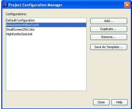
Figure 11-4
Project Configuration Manager
3. Click Add to open the Add Project Configuration dialog box. 4. Enter a name for your new configuration and click OK.
This name should be an identifier that describes the distribution that this configuration is used for. For example, some descriptive configuration names might be NokiaSeries40Bluetooth, SmallScreen256Color, or
HighResNoSizeLimit.5. Click Add again if you’d like to create another configuration. Otherwise, click Close to close the dialog box.
NetBeans IDE Tip
Configuration names are just strings and can be set to whatever you’d like. The only restrictions are that they must be valid Java identifiers and that they must not conflict with existing configuration names within the project.
Customizing Configurations
Once you have created your configurations, you may make customizations within the Project Properties dialog box that pertain to only one configuration. There are two basic principles of the configurations within the Project Properties dialog. First, by default, all configurations take the values set for the default configuration. Second, user-added configurations can override the default settings for any panel (other than the General panel) by unchecking the checkbox labeled Use Values from “Default Configuration.” Once this checkbox has been unchecked, that
configuration uses its own settings for the panel. The following is an example of this:
1. Right-click your project in the Projects window and select Properties.
2. Make sure DefaultConfiguration is selected in the Project Configurations drop-down box. In the Emulator Platform drop-drop-down box, select J2ME Wireless Toolkit 2.2, and in the Device drop-down box of the Platform panel, select DefaultGreyPhone.
4. Select the Platform panel. All controls in this panel should be disabled. This is because the configuration is currently drawing its values from
DefaultConfiguration.
5. Deselect the Use Values from “DefaultConfiguration” checkbox. All controls on the panel are now enabled, as they are no longer taking their values from the default configuration.
6. Change the Device combo value to DefaultColorPhone.
You have now configured the DefaultConfiguration to use the DefaultGreyPhone device and your user-added configuration to use the DefaultColorPhone.
Setting the Active Configuration for Your Project
At any time, only one configuration is active for your Mobility project. Project settings from the Project Properties dialog box are based on this active configuration.
You can view or set the active configuration in several ways:
[lb] Right-click the project node in the Projects window and hover over the Set Active Project Configuration menu option. The active configuration is marked by a bullet. You can click any configuration in this list to activate the selected configuration.
[lb] Right-click the project node in the Projects window and select Properties. Changing the selected configuration in the Project Configuration combo box activates the newly selected configuration.
[lb] Configurations for the Main project appears in the combo box located in the build toolbar. The selected item in the drop-down box is the active configuration.
Physical Structure of Mobility Projects with
Configurations
Once a project containing multiple configurations has been built, the
build folder will contain the build directories for the default configuration,
and the dist directory will contain its distribution JAD file and JAR file.
Additionally, the dist and dist directories will contain one subdirectory
for each configuration in the project. These subdirectories will hold the build and distribution files for the like-named configuration.
Reusing Project Settings and Configurations
Creating a project with several different configurations and settings within those
Duplicating Project Settings
If you have configured an entire project that has settings you would like to reuse on a new project, you can do so using the Duplicate Project command.
To reuse a project's settings in another project:
1. Right-click your project in Projects window and select Duplicate Project. 2. Optionally, update the Project Name and Project Location fields.
3. Select Create Empty Source Root or Copy All Sources, depending on your preference.
Whenever you select the Copy All Sources option, all files in the original project’s source root are copied to the src folder contained in the new project. This occurs even when the original project has an external source root.
Your newly created project has all of the settings and configurations from the original project. These may include some settings that are no longer appropriate (for example, JAD file and JAR file name, filtering options, and some JAD file attributes).
Using Project Configuration Templates
Alternatively, you might want just to reuse the settings from one or two configurations. You can do this with configuration templates, which allow you to create new configurations based on the saved settings of other useful configuration. Only the settings from panels that are not taking their values from the default configuration are stored in templates. They are very easy to create: 1. Right-click your project in Projects window and select Properties.
2. Click Manage Configurations.
3. Highlight the configuration that contains the reusable settings and click Save As Template.
4. In the Save Project As Configuration Template dialog box, enter a name for the template and click Save.
Templates are uniquely stored in the IDE, so choose a descriptive name.Now that you have saved this configuration template, it is possible to create new
configurations based on it:1. Right-click your project in the Projects window and select Properties.
2. Select Add Configuration from the Project Configurations combo box.
3. Select the template you would like to use from the Use Configuration Template combo box.
4. Modify the name of the configuration in the New Configuration Name text box if desired. Click OK.
This template-based configuration has the same settings as the template for each panel of the template that was not using the values from the default configuration.
NetBeans IDE Tip
Structuring Project Dependencies
Unlike other NetBeans project types, Mobility projects are based on the concept of a single source root that results in a single distribution JAR file. It is possible to simulate multiple source roots by setting up one project for each source root and then using project dependencies. It may be helpful to think of the source root containing the MIDlet as the application project, while all other source roots should be considered library projects.
NetBeans IDE Tip
There are no programmatic differences between Library and Application projects other than the option to include a MIDlet when creating an Application project. The differences between project types are purely conceptual in nature.
To structure your project dependencies:1. Right-click your application project in the Projects window and select Properties.
2. Highlight the Libraries & Resources panel in the Project Properties dialog b ox. 3. Click Add Project.
4. Navigate to the project root of a Library project and ensure that the correct Project JAR file is highlighted in the Select Project JAR Files dialog box. 5. Click Add Selected Project JAR Files.
6. Repeat for each Library project.
If there are interdependencies among the Library projects, these must be set up in the same manner. Note that dependencies may not be circular; if project A depends on project B, project B cannot depend on project A (or any other project that depends on project A).
Using Dependencies with Configurations
If your Library project and Application project make use of project configurations, it is important to take care when setting up the project dependencies. Though it is tempting to assume that the Application project will automatically depend on the correct version of the Library project (based on configuration name matching), this is not the case.
Assume, for example, you are working with an Application project that has configurations named SmallScreen and LargeScreen, and a Library project that has two configurations of the same name. To set up the dependency between the two projects:
1. Right-click your Application project in theProjects window and select Properties. 2. Select the Libraries & Resources panel in the Project Properties dialog box. 3. Select the SmallScreen configuration from the Project Configuration combo box
and then uncheck the Use Values from “DefaultConfiguration” checkbox. 4. Click Add Project.
5. Navigate to the project root of the Library project and highlight the project JAR file that is prefaced with /dist/SmallScreen in the Select Project JAR Files dialog box.
6. Click Add Selected Project JAR Files.
Managing the Distribution JAR File Content
By default, all class files resulting from compilation, as well as all nonsource files contained under the project’s source root folder, are placed in the distribution JAR file. All classes and resources specified in the Libraries & Resources panel are also placed in this distribution JAR file.
Your project may contain files under its source root that should not be distributed. These files can be filtered in the following manner:
1. Right-click your project in the Projects window and select Properties. 2. Select the Sources Filtering panel.
3. Select the default filters provided that are appropriate for your project. Hovering your mouse over the checkbox text displays which regular expression is used to filter files from the distribution JAR file.
4. The Select Application Packages/Files field displays, in tree format, all files under the source root that can be included. Selected files are distributed. Deselect a node, and notice that all children nodes are also deselected. If any node is deselected, all of its ancestor nodes are grayed out to indicate a partial selection.
5. Click OK to close the Project Properties dialog box.
The next time you build the project, the selected files and resources will not be added to the distribution JAR file.
Handling Project Resources for Different Configurations
One of the most common causes of device fragmentation is different screen sizes on mobile devices. Disparate screen sizes require different resources, and usually, it is not advisable to include unused resources in the distribution JAR file.
Imagine the scenario where your application has a fixed-size splash-screen image, and you want to include only the correct-size image with each configuration. There are two different methodologies that you can use to manage this problem using NetBeans Mobility Pack. Which method you should use depends on whether you are working with an existing project structure or have the freedom to handle the problem in any way that suits you.
Using Different Resource Locations
One technique is to create size-specific resource JAR files or folders that contain identically named resources. For example, you might have a directory structure like this:
/res/small/splashScreen.png /res/medium/splashScreen.png /res/large/splashScreen.png
Your source code would read simply:
Image splashScreen = Image.createImage("splashScreen.png");
Using Configuration-Specific Code Blocks and the Filtering Panel
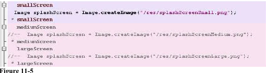
An alternative solution is to have distinctly named resources all contained under the project’s source root. So you might have a directory structure something like this:
/src/res/splashScreenSmall.png /src/res/splashScreenMedium.png /src/res/splashScreenLarge.png
[image:16.612.91.515.217.334.2]Then you would need three configuration-specific code blocks in your source code for the create statement, meaning that your source would look like the code in Figure 11-5.
Figure 11-5
Example of configuration-specific code blocks in the Source Editor
Finally, the Filtering Sources panel would be modified for each configuration such that only the used resource would be selected in each one.
Both of these solutions result in similar-size application JAR files that include only the used resources. Therefore, it is up to you which technique is best suited to your project structures.
Writing Code Specific to a List of Configurations
Perhaps one of the most uniquely challenging aspects of handling the device fragmentation problem has been managing differences in code between distributions of an application. The NetBeans approach to the problem has been to integrate a preprocessor into the build process that activates or deactivates sections of code based on which configuration is active at compile time.
The NetBeans preprocessor is a low-impact tool that uses Java comments both to define code sections and to activate and deactivate these sections. As such, all files before and after
preprocessing can be valid, syntactically correct Java source. This also ensures that the preprocessed files integrate seamlessly with the debugger.
NetBeans IDE Tip
Source files are always saved to the hard drive as though the
defaultconfiguration were active. This eliminates the VCS conflicts that could otherwise occur due to the local version’s having a different active configuration than the VCS version.
Creating a Code Block for a Single Configuration
If a block of code is appropriate only for a single distribution of your application, you can use these steps to mark that block as being configuration specific:1. Highlight the code section that you would like to be configuration specific.
2. Right-click the editor document and select Preprocessor Blocks |
ConfigurationName, where ConfigurationName is the name of the configuration you want to associate with the code section.
NetBeans IDE Tip
Only full lines of text may be associated with a configuration. If you would like to associate only part of a line with the configuration, first break the line into smaller sections and associate the sections appropriately.
This command can also be used to add a configuration to an existing block. Simply right-click inside the block that you would like to modify and select the configuration to add.
Creating a Code Block for Multiple Configurations
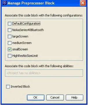
If you are a creating or modifying a code block that have multiple identifiers associated with it, it is often easiest to use the Manage Preprocessor Block dialog box. This dialog box allows you to add or remove any number of a block’s configurations or abilities.
1. Highlight the code section that you would like to be configuration specific. 2. Right-click the editor document and select Manage Preprocessor Block.
[image:17.612.230.382.423.603.2]3. In the Manage Preprocessor Block dialog box (shown in Figure 11-6), select the checkbox next to each configuration you would like associated with the code block.
Figure 11-6
Manage Preprocessor Block dialog box
Creating an Inverse Code Block for a Single Configuration
The NetBeans preprocessor understands another type of code block definition: the inverse block. Inverse blocks are commented in whenever the project’s active configuration is not found in the block’s definition.
You can create an inverse block for the active configuration in the following manner: 1. Highlight the code section that you would like to be configuration specific. 2. Right-click the editor document and select Inverted Block (active config name).
Alternatively, you can use the Manage Preprocessor Block dialog box and select the Inverted Block checkbox in addition to the target configurations.
Invoking this command on an existing block will toggle its inverted status.
Rules That Govern Block Selection
The rules that determine when an existing code block has been selected, or when a new block is created when invoking commands in the
Preprocessor Blocks menu, are listed here:
[lb] If the right-click occurs within an existing block, and no text has been highlighted, that block is considered selected.
[lb] If text has been selected when the context menu is opened, and that selection does not overlap with any existing block, any commands create a new block.
[lb] If text has been selected, and it fully encloses (or is fully enclosed by) one code block, that block is considered selected.
[lb] If text has been selected, and it comes into contact with more than one existing block, no blocks are considered selected.
[lb] If text has been selected, and it partially overlaps an existing block, no blocks are considered selected.
[lb] If text has been selected, and it comes into contact with a guarded block, no blocks are considered selected.
How to Interpret Code Block Visualization
The visualization of code blocks within the IDE is that of color highlighted sections. This visualization can help you quickly determine some
information about code sections:
[lb] Sections that are active for the currently selected configuration are gray. Also, code contained within the section is uncommented.
[lb] Inactive sections are pink. Each line in the code section is prepended with a specially formatted line comment (//--).
NetBeans IDE Tip
The state of the special comments within the IDE editor is unimportant, as the preprocessor runs before any compilation command and place the lines of each code block in the correct comment state.
If the special comments within the code blocks become out of sync with the actual state of the code block in the IDE, you can correct them by simply switching configurations. The preprocessor automatically fixes the errors.
Duplicating a Code Block
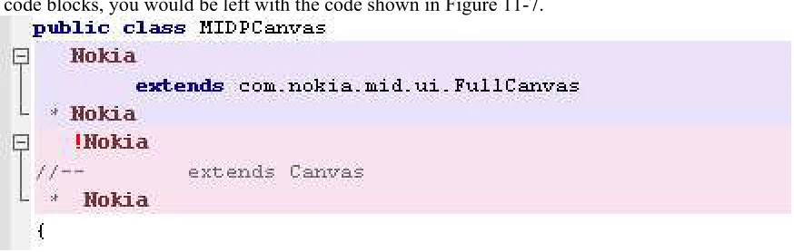
Sometimes, there is a section of code that must be defined differently for some configurations and that must exist even for configurations that don’t explicitly define a code block in the section. An example of this would be if your class definition is fragmented. For example, all of your configurations that will be deployed to Nokia devices might define your Canvas object like this
public class MIDPCanvas extends com.nokia.mid.ui.FullCanvas {
[image:19.612.88.525.305.444.2]while the rest of your configurations would just extend Canvas. After adding the appropriate code blocks, you would be left with the code shown in Figure 11-7.
Figure 11-7
Duplicated code blocks in the Source Editor
These types of blocks can be created in one step using the Create If / Else Block context-menu command:1. Highlight the code section that you would like to be duplicated. 2. Right-click the editor document and select Preprocessor Blocks | Create If / Else
Block (IdentifierName), where IdentifierName is the name of the identifier you want to duplicate the block for.
Two code blocks are created, each containing the highlighted code. The second code block is an inverse block.
You can also use the Create If / Else Block command on existing code blocks. Doing this adds the selected identifier to the code block and then create a new duplicate block with the selected Identifier in its header.
Using Configuration Abilities
always adding a certain group of configurations to the same code blocks. Or, when adding a new configuration to an existing project, you might find it onerous associating that configuration with each existing and appropriate code block.
In reality, code blocks are usually defined to address some specific feature of the platform to which that code will be deployed; and often, several deployment platforms share the same features and, thus, the same code blocks. To address these problems, configurations have the concept of abilities.
Abilities are identifiers that can be associated with code blocks in much the same way that configuration names are. Configurations can then be associated with as many abilities as desired. Once this is done, activating a configuration uncomments any code block containing either the configuration or any of its associated abilities.
For example, you might be creating an application with six different distributions. In your source, you create some code blocks that handle calls to a vendor-specific Bluetooth
implementation. Three of your target distribution platforms will have that specific Bluetooth API available. Rather than list in each code block those three configuration names, you would instead associate that code block with an ability called VendorSpecificBluetoothAPI. Then you associate it with the three configurations that support the Bluetooth API.
This makes maintenance much easier for existing code blocks. Now, if you decide to support a new device that has a certain ability, you can simply attach all appropriate abilities to the new configuration. Then it will automatically be compatible with all existing code blocks.
As such, it is almost always preferable to use abilities when creating code blocks rather than simply configurations. The only cases for using pure configuration names are when you are never planning on supporting more than a few platforms for a given application or when the code block is really specific to only one deployment platform.
Creating and Associating an Ability with a Configuration
To create and associate an ability with a configuration: Right-click your project in the Projects window and select Properties to open the Project Properties dialog box.
2. Select the Abilities panel.
3. From the Project Configuration drop-down box, select the configuration you would like to associate with the new ability.
4. Uncheck the Use Values from “DefaultConfiguration” checkbox (if you did not select DefaultConfiguration in the previous step).
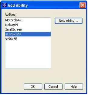
[image:20.612.234.379.561.718.2]Figure 11-8
Add Ability dialog box
6. If the ability you want to attach to the configuration is not in the Abilities list box, click the New Ability button and continue to the next step. Otherwise, select the ability or abilities you would like to attach and click OK.
7. Enter a name for your new ability. Ability names, like configuration names, can be any valid Java identifier strings. They should be as descriptive as possible, as they must be unique among all other abilities and configurations in the project. 8. Click OK to close the New Ability dialog box.
9. The newly created ability is listed and selected in the Abilities list box. If you are satisfied with the new ability, click OK to close the Add Ability dialog box. 10. Click OK to close the Project Properties dialog box. Your configuration is now
associated with the newly created abilities.
Once an ability is associated with at least one configuration in the project, that ability will appear in the Preprocessor Blocks editor context menu. Abilities can be treated exactly like configurations with regard to creating or modifying preprocessor blocks.
NetBeans IDE Tip
The list of abilities contained in the Abilities List view of the Add Ability dialog box contains all the abilities that are attached to configurations in any project that the IDE is currently aware of. The IDE is aware of more projects than those that are open, so don’t be surprised if you see some abilities there that don’t belong to any open project.
There is no Remove Ability button in the Add Ability dialog box, because it simply displays all abilities that are associated with any configuration. If you would like to remove an ability from this list, just make sure that it’s not used in any project that you’ve opened in the IDE.
Localizing Applications
In the mobile development world, there are many different ways of handling localization or translation of your product into different languages. The official support within the NetBeans Mobility Pack is based on the concept of using bundled message.property files. The messages file, as well as a small support class that uses it, can be generated for you automatically by the Localization Support Class template:1. In the Projects window, right-click the package you would like to contain your LocalizationSupport class and select New | Localization Support Class. If that option is not available, select File/Folder.
Alternatively, select File | New File (Ctrl-N) from the main menu.
2. Select the MIDP node in the Categories list box and then Localization Support Class in the File Types list, and click Next.
3. Optionally, fill in the following fields in the Name and Location panel of the wizard:
Class Name: The generated class’ name.
Messages Bundle Name: The name of the message bundle. Package: The package in which to create the files.
Error Message: The error message that is displayed when there is a problem loading the message bundle.
4. Click Finish to create the files in the locations displayed in the Created Class File and Created Bundle File fields.
The automatically generated support class should now appear in your project and can be modified as desired. The following process outlines how an existing application can be localized using the support class:
1. All hard-coded text strings from your application should be added to the created message.properties file using the following format:
PROPERTY_NAME=My Translatable Text String
2. The strings in your source files should then be replaced with code like this:
LocalizationSupport.getMessage("PROPERTY_NAME")
3. Once all strings have been added to message.properties, right-click the file node in theProjects window and select Add Locale.
4. Select a locale that you want to support from the Predefined Locales list box, or use the combo boxes at the top of the form to define a new locale.
5. Click OK.
6. Expand the message.properties node in theProjects window and double-click the newly added locale.
7. Translate all properties into the appropriate language.
8. Repeat these last five steps until all supported languages have been added.
This technique uses the microedition.locale property of the phone to determine which version of the message.properties file should be used. If the region is not found, the default bundle is used.
If you prefer, you can force a particular region to be used by calling the following code before using LocalizationSupport.getMessage():
LocalizationSupport.initLocalizationSupport("en_US")
In this case, the en_US version of the message.properties file is always used. Forcing a region is useful when you are planning on supporting only one language per distribution JAR file. The Filtering panel should be used to ensure that only the used properties file is bundled with the application.
Using the MIDP Visual Designer
Creating a New Visual Design To create a new visual design:
1. In the Projects window, right-click the package you would like to contain your visual design and select New | Visual Midlet. If that option is not available, select File/Folder.
Alternatively, select File | New File (Ctrl-N) from the main menu.
2. Select the MIDP node in the Categories list box and then Visual MIDlet or HelloMIDlet.java in the File Types list, and click Next.
3. Select the MIDP version for your MIDlet to use (according to the version supported by the device you are developing for) and click Next.4. Fill out the fields as described in Using Mobility File Templates earlier in this chapter, and click Finish.
Your visual design opens in the Flow Design view. If HelloMidlet was selected, the MIDlet will already contain a TextBox screen that displays the text “Hello, World!”
Adding Objects to the Component Palette
User-defined screens and items can be added to the component palette for use with the designer. Though the screen editor does not allow editing of all attributes of user-added components, they can still be used with the Flow Designer:
1. Ensure that the class you want to use is on your project’s classpath.
2. Click the button at the top of the component palette. This opens the MVD Component Palette Manager dialog box.
3. Click Add from Project. 4. Select the project that contains the object you want added to the component palette and click Next.
5. Select all the objects to add, using the Found MIDP Classes list.
All classes inheriting from Displayable or Item on the selected project’s classpath are shown in the list.
6. Optionally, use the Add to Category combo box to select the palette category to which the object will be added, and click Finish.
7. Click Close.
Your component(s) will now be available in the chosen category whenever you open the Visual Designer. This is true for any project you open. As such, it is possible that a class in the component palette won’t be on your project’s classpath.
Building a Small Application with the Visual Designer
The following steps illustrate how to create the skeleton of a two-screen application that could be used to send an SMS:1. Create a new visual design document and click the Flow Design button in the designer toolbar.
2. Click and drag the TextBox from the Screens group in the component palette to the Flow Designer.
3. Click and drag the transition source labeled Start Point on the Mobile Device screen to your newly added TextBox.
4. Click and drag the OK command from the Commands group in the component palette to your TextBox screen. Now add an Exit command to the same screen. 5. Click and drag an Alert from the Screens group in the component palette to the
Flow Designer.
6. Double-click the new Alert screen. It will open in the Screen Designer.
7. Click the Device screen where it reads <Enter Text>. This text box will now be editable. Enter the message "SMS Sent" and press Ctrl-Enter to save your changes.
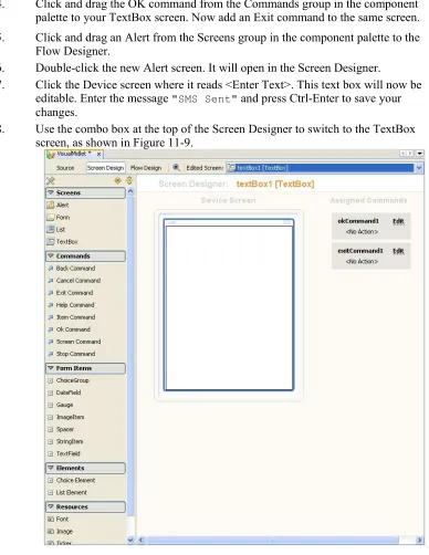
[image:24.612.94.482.75.577.2]8. Use the combo box at the top of the Screen Designer to switch to the TextBox screen, as shown in Figure 11-9.
Figure 11-9
Visual dDesigner with a TextBox screen added9. Click in the text box and delete the
<Edit Text> string. Again, press Ctrl-Enter to save your changes.
10. Use the property editor to set the Title property to "Enter SMS text:". 11. Click the Flow Design button in the toolbar to return to Flow Design view. 12. Click and drag the transition source labeled okCommand from the TextBox
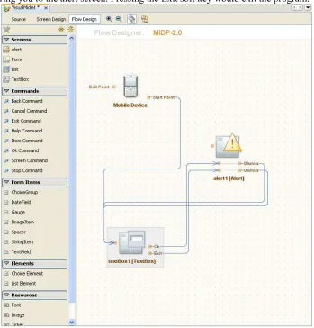
The Form Designer should now look similar to what is shown in Figure 12-10. If you were to run the application at this point, it would begin with a text box screen and OK and Exit options on its soft keys. Pressing the OK soft key would bring you to the alert screen. Pressing the Exit soft key would exit the program.
Figure 11-10
Visual Designer in Flow Design view and an Alert screen added14. Use Inspector view to select the okCommand that is located under the TextBox screen node.
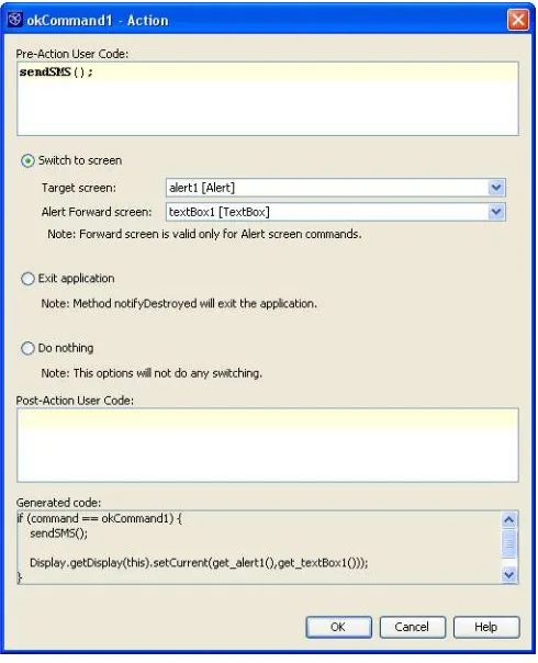
15. In the Properties panel, click in the Action property's value field to open the Action dialog box.
16. In the Action dialog box, enter sendSMS in the Callback Validation Method Name field, as shown in Figure 11-11, and click OK.
This action generates a method stub called sendSMS. This is where you could place the code that would handle sending an SMS. It is called each time the OK button is clicked, and if it returns False, the transaction does not occur. 17. Click the Source button in the Visual-Designer toolbar to view the source for
your application. The main code generated by the Visual Designer is folded. You should also see the sendSMS method. You can enter code here for SMS
handling, if you like.
Figure 11-11 Action dialog box
Understanding the Flow Designer
The Flow Designer visually represents the different paths that can be taken between your application’s different screens. Using this view, you can add or remove screens, as well as the transitions between them. It is also possible to modify the properties of the screens and transitions. The Flow Designer is composed of four parts: the component palette, the Inspector, the Flow Design panel, and a property sheet. Following is a quick overview of these panels, as well as their respective abilities.
Component Palette
The component palette (shown in Figure 11-12) contains groupings of all Java objects that can be added to your application with the designer. If an object does not exist in the component palette, it cannot be added to the application using the Flow Designer.
The following categories are used:
[lb] Screens: Contains items for creating Alert, Form, List, and TextBox. [lb] Commands: Contains an item for each command type defined in
javax.microedition.lcdui.Command. Commands are used as sources
[lb] Form Items: Items that can be added to Form screens.
[lb] Elements: Contains elements that can be added to Lists and ChoiceGroups.
[lb] Resources: Resources that can be used by other items. Includes Font,
Image, and Ticker.
[lb] Custom Components: Resources that can be used by other items. Includes Font, Image, and Ticker.
All groups can be expanded or collapsed individually by clicking the header bar containing the group name. The groups can be collapsed or
[image:27.612.263.348.265.635.2]expanded simultaneously by clicking the (collapse all) or (expand all) button at the top of the palette.
Figure 11-12 Component palette Inspector
Resources. Any objects from these groups that have been added to the design appear under their respective group header nodes.
If a node represents an object that can have action commands associated with it, it has an Assigned Commands group node containing each
assigned action. Similarly, objects that support elements or items contain an Elements or Items group.
Selected objects in the Inspector are highlighted in Screen Designer or Flow Designer view (if the object appears in the currently active design view). Additionally, the object’s properties are displayed in Property Sheet view.
Right-clicking a component node opens a menu consisting of standard node commands (Rename, Cut, Copy, Paste, Delete, Move Up, Move Down, and Properties).
Right-clicking the Action Command, Elements, or
[image:28.612.257.356.315.446.2]Items node opens a menu containing actions for adding a new node to the list or changing the order of the list.
Figure 11-13 Inspector
Property Sheet
A standard property sheet is visible when the designer is open. This property sheet shows the editable properties for any object selected in Designer or Inspector view.
The property sheet contains all MIDP2 properties for the selected object. Additionally, there are some items specific to the source code and components, as described here:
[lb] Instance Name: The name of the object.
[lb] Action Source: When a transition is selected that is initiated with a command, this property appears. It defines which command object to use as the transaction source.
[lb] Post-Callback Method: A method is created by this property value that is called after the component is initialized. Used only when Lazy Initialize is selected.
[lb] Action: Property that appears when an action command is selected. A special property editor is used to set this value.
[lb] Radio Buttons: Used to control which screen is shown when this
transaction occurs. Selecting nothing means there is no target. Selecting Exit means the application will end when the transition is followed. Selecting Switch enables the target screen drop-down box, which can be used to select a new screen.
[lb] Target Displayable: Contains all screens available in the visual design. The selected screen is the one displayed when the command is invoked.
[lb] Forward Displayable: Select what will be displayed after an alert. Appears only when a connection is selected that targets an alert.
[lb] Callback Validation Method Name: Entering a value in this field creates a method by that name in the source. This method returns a Boolean. If
the return value is True, the forward action will occur; otherwise, it is
skipped.
[lb] Post-Callback Method Name: Entering a value in the field creates a method by that name in the source. This method is called after the display is updated to the new value.
Additional properties are determined by what is supported by the associated object.
Several property types have special editors associated with them:
[lb] String Editor: A dialog box opens, containing a text box. Values entered in this text box are used as the property value. If the Use as Custom Code Expression checkbox is selected, the value entered in the text box is used as though it were Java code rather than as a static string. So, for example, entering "getTitle()" in an alert’s Title property when Use as Custom Code Expression is selected causes that component to be constructed with code like this:
alert = new Alert(getTitle(), "text", get_image2(), AlertType.INFO)
The user must implement a getTitle() method for the component to work properly.
Figure 11-14 Image dialog box
The Select Image list contains all images that will appear in the project’s distribution JAR file. As shown in Figure 11-14, selecting an image displays a preview of the image, as well as the dimensions, file size, and name of the file. Clicking OK sets the property to the path of the selected image.
[lb] Constraints: Selecting the Constraints property on TextBox objects opens the Constraints dialog box. Use the radio button to specify the restrictive constraint setting and the checkboxes to specify any additional constraint modifiers.
[lb] Font: Editing the Font property on Font resources opens the Font dialog box. This dialog box allows you to specify which font to use. Selecting Custom from the main radio button enables the dialog box’s font checkboxes; otherwise, the default or system font is used.
[lb] Layout: Editing the Layout property of any Form item opens the Layout dialog box. This dialog box allows you to specify properties that determine how the item will appear within the form.
Flow Designer
The main screen of the Flow Designer uses drag-and-drop to add and connect components in the MIDlet. All designs contain a Mobile Device element that represents the MIDlet’s start point.
Displayable components (screens) can be dragged from the component palette and dropped onto the Design screen. After a screen has been added, appropriate commands, elements, items, and resources can be added to it by dragging the object from component palette and dropping it on the screen.
Transition sources are displayed on the right side of the component to which they are attached. These are used to create transitions to different screens by selecting the transition source and dragging to the target screen. The connection is visualized in the design as a line.
Selecting a screen node highlights all transitions to and from that screen in a different color. Double-clicking a screen opens it in Screen Design view.
Toolbar
The toolbar of the Flow Designer has only two items:
[lb] Snap to Grid: Toggles between displaying and hiding a dotted grid on background of the designer page. Also determines whether screens snap to set locations or can be moved with complete freedom.
[lb] Realign Components: Realigns all existing screens to a grid pattern.
Understanding the Screen Designer
The Screen Designer allows you to customize screens that have been added to the visual design. It contains two main sections: the device screen and Assigned Commands, which will be discussed here.
Device Screen
The device screen simulates how the screen will appear on a real device. All elements, items, and resources (components) appear in the order in which they are listed in the Inspector view. Components can be dragged to new locations in the Inspector to change display order.
Hovering over a component highlights it with a dashed line. Clicking the component selects it and highlight it with a solid line. Clicking editable areas within a selected component (as shown with a moving dashed line) allows inline editing of the selected area. Noneditable sections of
components cannot be modified inline but usually can still be selected. As always, properties of the selected object appear in the properties sheet. New components can be dragged and dropped directly to the desired location of the device screen. Only components that are valid for the screen type are added. Appropriate elements and items can be added to existing components (for example, Choice Element objects can be added to existing Choice Group objects). Trying to add a component not
supported by the screen/object shows a standard Not Allowed icon. Right-clicking the device screen and selecting Set Screen Size brings up a dialog box in which you can set the height and width of the device screen in pixels. Clicking the (Activate Viewport) button simulates how the screen will appear on a device that has these dimensions. The
and buttons move this view up and down the design.
Assigned Commands
This list has a subsection for item commands as well. These commands appear only when you are editing a list screen; one Item Command box is displayed for each list element. They function in the same way as normal Assigned Commands boxes.
Toolbar
The Screen Design toolbar has a combo box containing all screens added to the visual design. Selecting a screen from this drop-down menu displays the screen in the Screen Designer.
Also in the toolbar is a Zoom icon. This simply increases the viewable size of all components in the screen within the IDE.
Deploying Your Application Automatically
NetBeans Mobility Pack provides you the ability to deploy your application. There are several methods of deployment, including simply moving the JAR file to a specified location on the local machine or using various protocols to move the file to a remote server. These options are specified in the Deploying panel of the Project Properties dialog box.
[image:32.612.111.494.364.668.2]1. Right-click your project in theProjects window and select Properties. 2. Select the Deploying node in the Category tree (as shown in Figure 11-15).
Figure 11-15
3. In the Select Deployment Method combo box, select the method you would like to use.
4. Optionally, set MIDlet-Jar-URL to a value other than the default (which is simply the JAR file name) by deselecting the Override JAR URL in JAD checkbox and entering a new value in the text field.
The remainder of the form is based on which deployment method you have selected above.
Copy
Use the Target Directory field to specify where the distribution JAR and JAD files should be copied.
FTP
1. Enter the server location in the Server field.
2. Optionally, use the Target Directory field to enter the remote directory to which the JAR file and JAD file should be copied.
3. Enter the remote server’s port in the Port field.
4. In the Separator field, specify the path separator used on the server. 5. Enter the remote username in the User Name field.
7. The Passive Mode Transfer checkbox is used to toggle between passive and active FTP mode. If you are having trouble connecting to your FTP server, and you are behind a firewall, you should select this checkbox.
SCP
1. Enter the server location in the Server field.
2. Check the Trust All Unknown Hosts checkbox to bypass the requirement that the host appear in your machine’s known hosts file (which is normally located at ${user.home}/.ssh/known_hosts).
3. Optionally, enter the remote directory to which the JAR and JAD files should be copied in the Target Directory field.
4. Enter the remote server’s port in the Port field. 5. Enter the remote username in the User Name field.
6. Select the Use Password Authentication radio button or, if you use public/private key authentication, select the Use Authentication Key radio button. If you select Use Authentication Key, enter the location of your private key in the Key File field..
WebDAV
1. Enter the server location in the Server field.
2. Optionally, enter the remote directory to which the JAR and JAD files should be copied in the Target Directory field.
Once you have set up this panel, right-click your project in the Projects window and select the Deploy Project command to deploy the project.
Incrementing the Application’s MIDlet-Version Automatically
The IDE has a built-in method that allows you to auto-increment the MIDlet-Version attribute in the JAR file each time you deploy the application. This can be useful, as some physical devices have a Check for Updates function for installed applications. If you increment the value, this device function automatically detects a new version when you deploy the application.
Deploying with an incremented value can be done in the following manner: 1. Right-click your project in theProjects window and select Properties. 2. Highlight the Attributes node in the Project Properties dialog box. 3. Select the MIDlet-Version record and click Edit.
4. Enter ${deployment.number} in the Value field. 5. Click OK.
Installing Nonstandard Emulator Platforms
This section describes the process by which you can use an emulator platform installed on your system that is not automatically recognized by the Java Platform Manager. Platforms are not automatically detected if they do not comply with the Unified Emulator Interface (UEI)
specification. This specification defines queries that allow external tools to determine the capabilities of the emulator (for example, supported MIDP and CLDC versions). Though most modern emulators are written in accordance with this standard, it can still be useful to still use the older, non-UEI-compliant emulators.
Warning
This is an advanced topic and requires manual modification of NetBeans system files. Modifying or creating these files incorrectly can cause instability within the IDE.
When platforms are added to the IDE via the Platform Management dialog box, an XML platform descriptor file is generated and stored in your NetBeans user directory
(userhome\config\Services\Platforms\org-netbeans-api-java-Platform) directory. The userhome directory is located by default at C:\Documents and
Settings\username\.netbeans for Windows machines and / home/username/.netbeans for Linux machines.
NetBeans IDE Tip
Emulators that are not UEI-compliant can sometimes be installed in the J2ME Wireless Toolkit as a device. Once installed in the J2ME Wireless Toolkit, the device appears in the Devices combo box of the Platforms panel when that platform is selected.
As an example, the Nokia 7210 emulator is not UEI compliant but is one of the remaining MIDP 1.0 Nokia emulators available for development. To install this platform, you can create and save the following platform descriptor file in the previously mentioned directory:
<?xml version='1.0'?>
<!DOCTYPE platform PUBLIC '-//NetBeans//DTD J2ME PlatformDefinition 1.0//EN' 'http://www.netbeans.org/dtds/j2me-platformdefinition-1_0.dtd'> <platform name="Nokia_7210"
home="C:\Nokia_7210" type="CUSTOM" displayname="Nokia 7210" srcpath=""
docpath="${platform.home}/docs/api,${platform.home}/docs,$ {platform.home}/docs/NokiaUI,${platform.home}/docs/tooldocs" preverifycmd=""{platformhome}{/}bin{/}preverify"
{classpath|-classpath "{classpath}"} -d "{destdir}" "{srcdir}""
runcmd=""{platformhome}{/}bin{/}7210.exe" "{jadfile} ""
debugcmd="java -classpath "{platformhome}{/}tools{/} emulator.jar" -Demulator.home="{platformhome}"
com.nokia.phone.sdk.Emulator -classpath "{platformhome}{/}lib{/} classes.zip" -debugger -dbg_port {debugaddress} -port 2800 " {jadfile}""
>
<device name="Nokia_7210"
securitydomains="real_life,manufacturer,trusted_3rd_party,untrusted,cus tom,minimum" description="Nokia 7210 Emulator">
<configuration name="CLDC" version="1.0" displayname="CLDC" classpath="${platform.home}/lib/classes.zip" dependencies="" default="true"/>
<profile name="MIDP" version="1.0" displayname="MIDP" classpath="${platform.home}/lib/classes.zip" dependencies="" default="true"/>
</device> </platform>
NetBeans IDE Tip
A DTD for the XML format can be found at www.netbeans.org/dtds/j2me-platformdefinition-1_0.dtd and contains useful information to assist in creating these descriptor files.
There are several things to notice in platform descriptor. First, items surrounded by {} are replaced with runtime values when any action is taken using the platform. Second, if quotation marks are required around any parameters at runtime, those quotes should be added to the platform descriptor file as ".
The file begins with a standard XML header:
<?xml version='1.0'?>
<!DOCTYPE platform PUBLIC '-//NetBeans//DTD J2ME PlatformDefinition 1.0//EN' 'http://www.netbeans.org/dtds/j2me-platformdefinition-1_0.dtd'>
Following the header is the platform element. This is the primary element of the document, and it takes the following attributes:
[lb] name: identifies the platform within the IDE. This must be a unique identifier. [lb] home: the folder in which the platform is installed.