THE EFFECT OF VARIOUS SPLINTING MATERIALS ON THE
ACCURACY OF OPEN TRAY IMPLANT IMPRESSIONS-
AN INVITRO COMPARATIVE STUDY
Dissertation submitted to
THE TAMILNADU Dr. M.G.R. MEDICAL UNIVERSITY
In partial fulfillment for the Degree of
MASTER OF DENTAL SURGERY
BRANCH I
INTRODUCTION
Osseointegrated implants have provided alternative treatment solutions to conventional
prosthesis for patients who lost their teeth and have achieved predictable long-term results9, 14.
An accurate and passively fitting prosthesis as well as error-free surgical procedure is mandatory
for long term implant success29.
The fabrication of superstructures with a passive fit is the major objective of making an
implant-supported prosthesis . In order to obtain a passive fit prosthesis the impression
procedure needs to be accurate. An accurate impression will help in the success of the implant
prosthesis.
This concept of passive adaptation has been defined as a strictly tolerated metal to metal
interface between an implant superstructure and the implant abutments. Failure to produce a
passive fit can result in the generation of stresses at the implant abutment interface, which may
lead to complications and mechanical failure5.
The uneven distribution of occlusal load and torquing put stress on the implant superstructure
which will lead to marginal bone loss and failure of implants. This leads to mechanical problems
like loosening of screws and fatigue fractures of implant components66.
Hence to connect a multi-unit implant prosthesis with a passive fit in clinical situation, will be
a challenge as there are many potential inaccuracies with current materials. This includes
dimensional changes in impression materials, investment materials, wax and acrylic pattern,
expansion of gypsum die product and volumetric shrinkage of metal casting on solidification56.
Among these variables, the precise transfer of the spatial relationships of implants from the
implant framework. Therefore, clinicians should strive for improving the transfer accuracy of the
impression analog31. Various techniques have been suggested to achieve an accurate master cast.
Anatomic constraints sometimes make it necessary to surgically position implants at an angle
that are not optimal for prosthetic restorations. Similarly, many researchers have evaluated the
accuracy of implant impression materials and better results have been obtained with polyether
(PE) and polyvinylsiloxane (PVS) 17, 20 in comparison to condensation silicone, polysulfide,
irreversible hydrocolloid, and plaster materials. Similar data also exist in terms of splinting,
angulation, or different impression materials, respectively.
There are two main techniques for dental implants impression, the direct (open tray) and
indirect (closed tray) impression technique. In the open tray technique, the impression coping is
incorporated in the impression and is removed from the mouth, together with the set impression.
In the closed tray technique, the impression coping is retained in the mouth when the set
impression is removed7.
To ensure maximum accuracy, some authors emphasized the importance of splinting
impression copings together intra-orally before making an impression. Various materials such as
acrylic resin, dental plaster, bite registration silicone, and polyether (PE) have been used as
splinting materials with varying degrees of accuracy19.
With regard to splinting the impression copings, there are many controversies that exist since
Branemark et al emphasized the importance of splinting impression copings together before
registration of multiple implant impression9. The common practice of joining the direct transfer
copings with acrylic resin is an attempt to stabilize the copings against rotation during fixture or
various literature studies showed no significant differences between the values obtained with
acrylic resin splinted versus unsplinted groups in impression technique23.
Studies involved multiple variables of techniques and materials, the consistent findings were
one of the distortions resulting from the transfer manipulations. The same objective could be
partially accomplished with a rigid impression material or an elastic material with a low
flexibility, both of which do not introduce the polymerization shrinkage variables inherent in the
use of acrylic resin.
Vigolo et al49 suggested that the impression technique involving square impression copings
which were previously airborne particle abraded and adhesive coated and splinted together with
autopolymerizing acrylic resin could improve accuracy of the master cast than non-modified
squared transfer copings which were not splinted.
Cabral Leonardo and Carlos13 compared four impression techniques involving indirect
impression technique with tapered transfer copings, direct impression technique with unsplinted
squared transfer copings, direct impression technique with squared transfer copings splinted with
acrylic resin, and direct impression technique with squared transfer copings with acrylic resin
splints sectioned 17 minutes after setting and welded with the same resin and concluded that the
direct impression technique with squared transfer copings with acrylic resin splints sectioned and
welded after setting had better results than the other techniques studied.
Among the direct impression techniques, both splinting and non-splinting have been
advocated for accurate impressions23. Splinting with impression plaster, resin or bite registration
material are recommended for maintaining a more accurate inter implant relationship although
and dimensionally stable material a newer material BisGMA has been used to splint the
impression copings.
The purpose of this in vitro study was to evaluate the effect of dimensional stability of
conventionally used and advanced splinting materials on the accuracy of master casts.
AIM AND OBJECTIVE
AIM:
The study is aimed at evaluating the accuracy of the master cast using open tray impression
technique with conventional and novel splinting materials.
OBJECTIVES:
1. To determine the linear inter-implant distances in the master cast obtained by splinting
the impression copings using auto-polymerising acrylic resin (pattern resin).
2. To determine the linear inter-implant distances in the master cast obtained by splinting
the impression copings using Pro temp (bis-GMA) syringable temporization material.
3. To determine the linear inter-implant distances in the master cast obtained by splinting
the impression copings using polyvinylsiloxane (putty consistency).
4. To compare the linear inter-implant distances in the master cast obtained by splinting the
impression copings using auto-polymerizing acrylic resin (pattern resin), Pro temp
(bis-GMA) syringable temporization material and polyvinylsiloxane (putty consistency).
The null hypothesis H01of the study assumes that there no significant difference in the linear
resin (pattern resin), Pro-temp (bis-GMA) syringable temporization material and
polyvinylsiloxane (putty consistency).
The null hypothesis H02 of the study assumes that there is a significant difference in the linear
inter-implant distances in the master cast obtained by splinting with auto-polymerizing acrylic
resin (pattern resin), Pro-temp (bis-GMA) syringable temporization material and
polyvinylsiloxane (putty consistency).
REVIEW OF LITERATURE
MARK SPECTOR et al in 199042 did a study for evaluating the impression techniques for
Osseointegrated implants. They developed an experimental model to test the accuracy of three
impression techniques and the components used to make the transfer records. In technique I a pin
retained transfer coping united with autopolymerizing resin and the impression was made with
polysulfide material. In technique II a polyvinyl siloxane impression was made in a stock tray
over hydrocolloid transfer copings. In technique III a condensation silicone impression was made
in a stock tray over hydrocolloid transfer copings. They described that there was no significant
differences between the three methods and further concluded that distortions with
autopolymerizing acrylic resin increase proportionally to the mass of the resin involved and
distortions with polyvinyl siloxane and condensation silicone may be due to the difficulty in
accurate orientation of the impression coping and abutment replica assembly in the final
impression. Sectioning of the impressions often demonstrated air entrapment and incomplete
seating of the impression tray, which may have impeded accurate placement of the transfer
MARK BARRETT et al in 199341 did a clinical research on the accuracy of six impression
implants techniques using irreversible hydrocolloid, impression plaster, polyether and polyvinyl
siloxane and concluded that there was no significant difference between the techniques for the
square copings but that there was a significant loss of accuracy with the tapered copings.
DAVID ASSIF et al in 199418 described a modified impression technique for
implant-supported restoration which involves the use of a modified autopolymerizing resin custom tray to
allow splinting of the impression copings directly to the tray and concluded that this method
eliminates the use of the dental floss-autopolymerizing resin complex, thus decreasing resin
distortion and simplifying the clinical procedures.
GAMAL BURAWI at al in 199723 did a study on the comparison of the dimensional accuracy
of the splinted and unsplinted impression techniques for the Bone-Lock implant system. They
constructed a stone model incorporating five implants. They used this model and compared the
dimensional accuracy of a splinted and unsplinted impression technique. They concluded that the
splinted technique exhibited more deviation from the master model than the unsplinted model.
This was primarily associated with rotational discrepancies around the long axes of the implants
for the splinted technique.
SOUHEIL HUSSAINI et al in 199761 did a study on one clinical visit for a multiple implant
restoration master cast fabrication. They used an open tray and acrylic resin to splint the transfer
copings. They sectioned and then rejoined the resin between the transfer copings and poured the
impression by joining the analogs with impression plaster and then sectioned it and rejoined it
technique facilitated the fabrication of the final casting by eliminating the necessary clinical
time to obtain solder indexes, and thus minimizing the inconvenience to the patient.
DAVID ASSIF et al in 199919 did a study on the accuracy of implant impression techniques
using three different splinting materials namely autopolymerizing acrylic resin, dual core acrylic
resin and plaster and concluded that Impression techniques using autopolymerizing acrylic resin
or impression plaster as a splinting material were significantly more accurate than dual-cure
acrylic resin. Plaster is the material of choice in completely edentulous patients, since it is much
easier to manipulate, less time consuming, and less expensive.
BELINDA GREGORY et al in 19998 described a two-step pick-up impression procedure for
implant-retained overdentures. This study describes a procedure that uses 2 steps, the first is
conventional border molding and impression in an individualized tray that fits over the implant
abutments and the second step involves attachment of the implant impression copings to the tray
and picking up the copings from the mouth. They concluded that the resultant master cast is
accurate in terms of soft tissue detail, position of implant components, and relat ionship between
soft tissue and implants.
ALVIN WEE in 20003 did a comparative study of impression materials for direct
multi-implant impressions. In this study they evaluated the accuracy of solid multi-implant casts fabricated
from different impression materials. Two direct transfer implant impressions were made using 8
different impression materials. They concluded that the addition silicone impression material is
the most suitable material for making multiple implant impressions.
HERBST et al in 200026 did a comparative study on four impression techniques in terms of
with tapered and squared type impression copings not splinted, squared impression copings
splinted with autopolymerizing acrylic resin and with a lateral extension on one side not splinted.
They concluded that the dimensional accuracy of all the techniques was exceptional and the
observe differences can be regarded as clinically negligible. The results of this study suggest that
there seems to be no clinical advantage in splinting impression transfer copings with an
autopolymerizing acrylic resin.
YASUYUKI MATSUSHITA et al in 200268 described a modified implant impression
technique which involves seating of the impression copings on the implants secured with guide
pins and an opening on the buccal side of the tray near the implants is prepared along with holes
in the tray to allow the head of the guide pins to protrude without contacting the tray during
impression making. A light-bodied impression material is used to record the area around the
remaining teeth and injection-type impression material is placed through the side opening until
the material flows from the holes at the top and lingual edge of the tray. After the impression
material as set, the impression containing the copings is removed. This technique forms a clear
impression of the soft tissue around the implants.
NOPSARAN CHAIMATTAYOMPOL et al in 200246 proposed a simple method of making
an implant-level impression when presented with limited space, unfavorable implant positions,
or problematic implant angulations. This technique describes the use of titanium or plastic
implant index copings as impression copings for an implant-level impression. Implant index
copings were invented to index the hexagon position of the implant and relate the implant
position to the adjacent teeth at Stage I surgery. Indexing the implant at stage I surgery enables
the appropriate abutment and provisional fixed prosthesis to be inserted immediately at stage II
after stage II surgery and provisional prosthesis placement even later, the patient receives a fixed
provisional prosthesis on the day of stage II surgery.
PAOLO VIGOLO et al in 200349 did a study on the accuracy of three techniques used for
multiple implant abutment impressions. Impression was made with polyether impression
material using three different techniques with non-modified square impression copings, those
joined together with autopolymerizing acrylic resin and others that had air borne particle-abraded
and adhesive coated. They concluded that the improved accuracy of the master cast is achieved
with the use of square type impression copings joined with autopolymerizing resin. The results
of this study suggested that splinting implant impression copings with autopolymerizing resin or
airborne particle abrading and coating the copings with impression adhesive before impression
making should result in more accurate working casts. Because splinting with resin is not the
preferred option when an immediate loading multiple implant impression is made, the airborne
particle abrasion/impression adhesive technique should be considered.
JASON BURNS et al in 200327 did a study on open tray implant impressions. In this they
compared the accuracy of impressions made from polycarbonate stock trays and rigid custom
made trays. Within the limits of this in vitro study, rigid custom trays produced significantly
more accurate impressions than the polycarbonate stock trays. The stock trays used in this study
could not produce accurate impressions consistently. For analogs with a 20-mm separation, there
was a difference in medians of 10mm in accuracy between the stock and custom trays. They
concluded that the rigid custom trays produced significantly more accurate impressions when
PAOLO VIGOLO et al in 200450 did a study on the evaluation of impression techniques
for multiple internal connection implant prostheses. A reference acrylic resin model with 4
internal connection implants was fabricated. Three groups of this model were made with
different impression techniques. In one group, nonmodified square impression copings were used
and in the second group, the copings were joined together with autopolymerizing acrylic resin
and in the third group, impressin copings previously airborne-particle abraded and coated with
adhesive were used. They concluded that the accuracy of definitive cast was better when the
impression copings joined together with autopolymerizing resin were used.
NICKOLAS EID in 200447 described an implant impression technique using a plaster index
combined with silicone impression material. The flexibility of the elastomeric impression
material is use to capture the undercut intraoral topography and the splinting effect of the plaster
to improve the accuracy of the fit of the prosthetic components. This technique reduces the misfit
of the framework and it can be used in both completely and partially edentulous patients.
ABBAS in 20051 described the use of wax spacers for putty-wash impression for snap-on
impression copings and concluded that relief of the putty impression material must be
accomplished to provide sufficient space for the wash material. Inadequate space may result in
displacement of the impression assembly and a distorted impression.
KONSTANTINOS et al in 200635 proposed a simple impression technique for dental implants
placed in close proximity or adverse angulations by the use of modified impression copings. In
this technique a retained impression coping is placed on one of the implants and is secured with
longer interferes with proper seating on the second implant and undercuts are prepared on both
surfaces of the coping. The impression copings are the connected with low shrink
auto-polymerizing polymethylmethacrylate resin. A custom tray made from PMMA with an access
window directly above the region of implants is made for direct transfer method and the final
impression is made with medium viscosity polyether.
BULENT ULUDAG et al in 200611 described an alternative impression technique for implant
retained overdenture. According to them the resilience difference between the mucosa and
implant should be considered as an important factor for making impressions of implant retained
overdentures. They suggested the combined use of zinc oxide eugenol impression material with
elastomeric impression material in order to record the alveolar mucosa in a functional state and
the implant components accurately.
BRAIN MYUNG et al in 200610 used a solid bar splint for open-tray implant impression
technique which involves a direct impression technique using square transfer coping splinted
with a solid acrylic bar and autopolymerizing resin and concluded that the use of solid bar may
decrease the amount of polymerization shrinkage due to the smaller amount of acrylic resin
needed and improved efficiency.
CHEE et al in 200616 described impression techniques for implant dentistry. According to the
author the object of impression making in implants is to accurately relate an analogue of the
implant to the dental arch. In this two types of impression coping has been described. In transfer
type impression coping no custom tray is required. They remain in the mouth after the removal
of set impression. They are indicated in cases of limited mouth opening. In pick up type
removed from the mouth together with the set impression. The impression material used is
usually an elastomeric impression material and the two types most widely used shown to be the
most appropriate are polyether and polyvinyl siloxane impression materials.
HEATHER CONRAD et al in 2007 did a comparative study on the accuracy of two
impression techniques with angulated implants. The authors stated that accurate recording of
implant locations is required in order to have a properly supported restorations and do not place
additional stress on the implants. Angulated implants may result in inaccurate impressions. They
made impressions of the definitive cast with angulated implants by means of open tray and
closed tray technique. They concluded that the average angle errors for the closed and open tray
impression techniques did not differ significantly. There was no interpretable pattern of average
angle errors in terms of implant angulation and implant number. The amount of distortion was
similar in all combinations of impression technique, the implant angulation, and number.
HEEJE LEE et al in 200825 did a study on the accuracy of implant impressions. The purposes
of this study were to investigate the accuracy of published implant impression techniques and
examine the clinical factors affecting implant impression accuracy. The review of abutment level
or implant level internal connection implants indicated that there was greater accuracy with the
splint technique than with the non-splint technique. For situations in which there were 3 or fewer
implants, most studies showed no difference between the pick-up and transfer techniques,
whereas for 4 or more implants showed higher accuracy with the pick-up technique. Polyether
and Polyvinyl siloxane were the recommended materials for the implant impressions.
AUDREY SELECMAN et al in 20095 described a technique for making an implant-level
less than 2 mm apart from the restorative platform and had an estimated 20-degree convergence.
The distal coping was placed first to ensure access and the anterior coping was conservatively
modified until it could be placed without obstruction. Removing the plastic increased the
flexibility of the coping and partially eliminated its retentive features and the definitive
impression was made with a medium-body, hydrophilic, addition-reaction silicone material. The
implant analogs were then placed on the impression copings within the impression, and the
definitive cast was poured in type IV dental stone and evaluated for prosthetic design. They
concluded that solid plastic, press-fit, closed-tray impression copings can be considered an
alternative to other more accurate and reliable methods when the creation of an implant-level
definitive cast is challenged by implant positioning.
SANG-JIK LEE et al in 201157 did a study to evaluate the effect of dimensional stability
of splinting material on the accuracy of master casts. Impressions were made after splintinf the
square impression by different techniques namely splinting with pattern resin and sectioned,
splinting resin just before the impression procedure, splinting with impression plaster and
polyvinyl Siloxane bite registration material and concluded that splinting the copings with
autopolymerizing resin after the compensation of polymerization shrinkage and splinting with
impression plaster enhances the accuracy of master cast.
MANESH LAHORI et al in 201138 discussed the various impression techniques in
implantology. They concluded that among the impression materials the material of choice is
addition silicone as it does not leave any by-products and its good stability and polyether due to
its excellent rigidity and among the impression techniques implant level open tray impressions is
abutment level closed tray impressions are ideal for single implant impressions and multiple
parallel implants.
ALI GOOYA et al in 20122 described a modified impression technique for mandibular
implant-retained overdenture. This technique uses a custom tray to make an accurate functional
impression in implant-retained overdentures which will register precise implant’s position
because they are splinted together. It can be used in both bar and ball attachment overdentures
with all kinds of implants.
NAYEREH RASHIDAN et al in 201245 did a comparative study on the accuracy of implant
impressions with different impression coping types and shapes using polyether impression
material to obtain precise definitive casts and concluded that the shape of the impression coping
had more impact on impression inaccuracy than the impression technique. Understanding of the
magnitude and variability of distortion when employing certain impression-making methods and
impression coping shapes helps the clinician to select a better implant component and impression
technique.
ERICA DORIGATTI et al in 201221 did a study on the comparison of the accuracy for three
dental impression techniques. The accuracy of impression techniques using tapered, squared and
modified square impression copings for implant-supported prostheses were compared. They
concluded that tapered coping technique was technically easier to work whereas squared and
modified squared coping techniques did not present any clinical advantage and did not improve
the dimensional accuracy of the die stones to interpret a clinical situation.
JUNPING BERGIN et al in 201332 did a comparative study of photogrammetric and
assess the feasibility of using a photogrammetric technique to record the location and orientation
of multiple implants and to compare the results with those of a conventional complete-arch
impression technique. They concluded that the photogrammetric method is capable of achieving
levels of accuracy and repeatability that are comparable to the conventional impression technique
and that the prototype photogrammetric method has the potential to serve as an alternative to
conventional impression procedures for implant supported prosthesis impressions.
KHALED ABDULLAH et al in 201334 did a comparative study on the accuracy of implant
impression with coded healing abutments and different implant angulations and concluded that
the casts fabricated from the coded healing abutment impressions are less accurate than those
fabricated from splinting the impression copings and further concluded that the accuracy of fit
was not influenced by the implant angulation or position for either impression technique or by
the Encode healing abutment height for the Encode impression technique.
ROXANNA et al in 201355 did a study on the precision of fit between implant impression
coping and implant replica pairs for three implant systems. The selected implant systems
represent the 3 main joint types used in implant dentistry namely the external hexagonal, internal
trilobe, and internal conical. The results of the study confirmed that implant systems differ in
precision of fit. Vertical precision between paired implant components is a function of joint type
and the tightening force applied to the guide pin. The magnitude of vertical displacement with
applied torque is greater for conical connections than for butt joint connections. The rotational
freedom between paired components is unique to the implant system and is presumably related to
the machining tolerances specified by the manufacturer. The angular positioning of impression
copings varies among implant systems and may result in errors that will be magnified in
BALOUCH et al in 20137 did a study on the comparison of dimensional accuracy between
open-tray and closed-tray implant impression technique in 15° angled implants and concluded
that closed tray impression method on angulated implants seems to have a significant effect in
reducing the dimensional changes in comparison to open tray method which is attributed to its
simplicity, accuracy of operator in implementing the technique and application of custom tray
instead of prefabricated tray. Therefore closed tray method is recommended due to its more
simple application and lower impression time.
SEVCAN et al in 201458 did a study on the digital evaluation of the accuracy of impression
techniques and materials in angulated implants using two different impression techniques,
splinted direct and indirect and 3 different impression materials namely polyether, vinyl
polysiloxane and polyether silicone and made models simulating parallel and angulated implants.
They concluded that the angulation and impression technique were found to be effective on the
accuracy of implant impressions. For parallel implants, more accurate impressions were obtained
with splinted direct technique and there was no significant difference between polyether and
polyvinyl siloxane however polyether silicone showed higher deviations. In the presence of
angulated implants the most accurate impression material was vinyl polysiloxane and the most
accurate technique was splinted direct technique.
ANIL SHARMA et al in 20154 described contemporary impression techniques in implant
prosthodontics. The aim of this article is to describe and evaluate the clinical efficacy of
impression techniques in implant therapy for transferring information to the laboratory. They
concluded that the selection of the impression technique and henceforth the tray depends upon
the coping design. A square coping requires an open tray and the technique is therefore the direct
implants bring along with them the problem of nonparallelism and the use of the indirect
technique has shown to cause errors in the fitting of the framework. Bone loss and even loss of
integration has been attributed to this misfit and pressure on the abutments causing them to tilt or
splay apart causes the rigid implant body in the bone to be subject to stress. To increase the
accuracy of the impression technique for multiple implants using the direct technique the direct
transfers are splinted with acrylic. The shrinkage of acrylic however can introduce errors by
causing the implants to move closer.
SUNANTHA SELVARAJ et al in 201663 did a study on the comparison of implant cast
accuracy of multiple implant impression technique with splinting materials such as
autopolymerizing acrylic resin (GC pattern resin) and Pro temp TM (bis-GMA) syringable
temporization material and concluded that the master cast obtained by both the splinting material
exhibits no difference from the reference model. Hence bis-GMA can be used, which is easy to
handle, less time consuming, less technique sensitive, rigid, and readily available material in
clinics.
RAVISHANKAR et al in 201651 did a study to investigate the accuracy of two kinds of
impression techniques (open and closed tray) with three impression materials namely
polyvinylsiloxane, polyether, vinylsiloxanether on angulated implants and two types of splinting
were carried out with floss and pattern resin and the second with a plastic rod (coffee stirrer) and
resin and concluded that vinylsiloxanether impression material yielded more accurate casts than
those of Polyvinylsiloxane and Polyether. Splinting with floss and pattern resin was found to be
METHODOLOGY
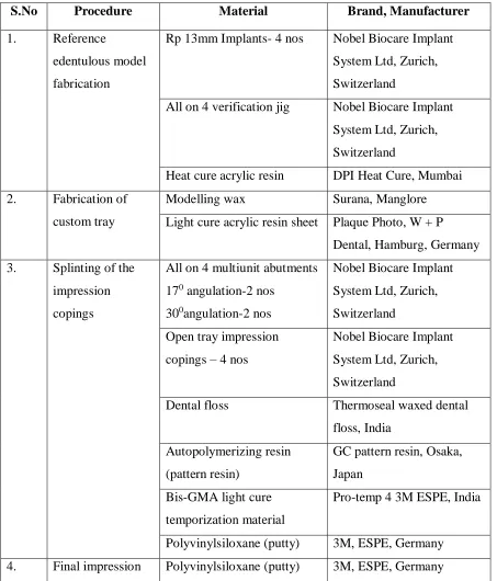
Table 1: Materials used in the study
S.No Procedure Material Brand, Manufacturer
1. Reference
edentulous model
fabrication
Rp 13mm Implants- 4 nos Nobel Biocare Implant
System Ltd, Zurich,
Switzerland
All on 4 verification jig Nobel Biocare Implant
System Ltd, Zurich,
Switzerland
Heat cure acrylic resin DPI Heat Cure, Mumbai
2. Fabrication of
custom tray
Modelling wax Surana, Manglore
Light cure acrylic resin sheet Plaque Photo, W + P
Dental, Hamburg, Germany
3. Splinting of the
impression
copings
All on 4 multiunit abutments
170 angulation-2 nos
300angulation-2 nos
Nobel Biocare Implant
System Ltd, Zurich,
Switzerland
Open tray impression
copings – 4 nos
Nobel Biocare Implant
System Ltd, Zurich,
Switzerland
Dental floss Thermoseal waxed dental
floss, India
Autopolymerizing resin
(pattern resin)
GC pattern resin, Osaka,
Japan
Bis-GMA light cure
temporization material
Pro-temp 4 3M ESPE, India
Polyvinylsiloxane (putty) 3M, ESPE, Germany
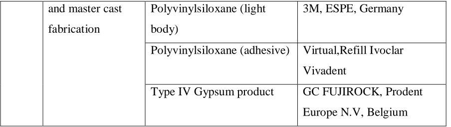
and master cast
fabrication
Polyvinylsiloxane (light
body)
3M, ESPE, Germany
Polyvinylsiloxane (adhesive) Virtual,Refill Ivoclar
Vivadent
Type IV Gypsum product GC FUJIROCK, Prodent
[image:20.612.66.518.71.199.2]Europe N.V, Belgium
Table 2: Equipment used in the study
S.No Procedure Instrument Brand, Manufacturer
1. Polymerisation of the
light cured pattern
Light curing unit Sibari Sr620, SIRIO
DENTAL, Italy
2. Measurement of inter
implant distances
Profile projector HB 350, Starrett Sigma,
North Yorkshire, England
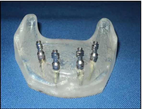
Fabrication of the reference edentulous model:
A reference wax model (figure 2) with four implants Rp-10mm (Nobel Biocare Implant System
Ltd, Zurich, Switzerland) was positioned in the mandibular ridge at an angulation of 00in the
anterior region and at an angulation of 450in the posterior regionusing an All on 4 guide (Nobel
Biocare Implant System Ltd, Zurich, Switzerland) (figure 3) and a Ney surveyor
(DentsplyCeramco, Germany)(figure 4)for proper orientation.The reference model mimics a
mandibular implant-supported overdenture situation15, 36 (figure 5). Three stoppers, one in the
anterior and two in the posterior region were made in the land area of the mandibular reference
model to ensure the proper orientation of the impression trays. The reference model is then
Fabrication of the custom tray:
Using the reference model fabricated in heat cure as a preliminary cast, a spaced primary cast
was made. In order to obtain uniform spacer, 3 mm even spacer was adapted onto the reference
modelusing modelling wax (Surana, Manglore)(figure 7) and the impression was made and
spaced primary cast was obtained (figure 8). Twelve custom trays (four per group) with windows
in the anterior region were made using light cure acrylic resin sheet (Plaque Photo, W + P
Dental, Hamburg, Germany) (figure 9)of 2 mm in thickness48. All the custom trays are uniformly
spaced and are cured in a light curing unit (SibariSr620, SIRIO DENTAL, Italy)(figure 11) using
visible light of wavelength 320-550nm for a period of 5 minutes. To ensure dimensional stability
of custom tray, the trays are left undisturbed for 24 hours prior to the impression making. A set
of twelve custom trays were made (four per group) (figure14).
Splinting of the impression copings:
The “All on 4”multiunit abutments (Nobel Biocare Implant System Ltd, Zurich,
Switzerland) of 170angulation in the anterior region and 300angulation in the posterior region are
screwed to the implant body34. The open tray impression copings45 (Nobel Biocare Implant
System Ltd, Zurich, Switzerland) are then screwed to the multi-unit abutments at 15Ncm torque
(figure15).The open tray copings were primarily splinted with dental floss19, 57 (Thermoseal
waxed dental floss, India) (figure 16, figure 17).
In Group A, Autopolymerizing resin65 (GC pattern resin, Osaka, Japan) was mixed in the ratio
of 2 g–1 ml. When the resin reached the dough stage, it was packed around the impression posts
and the dental floss. The splint was allowed to polymerize for 4 minutes. The splint was
by polymerization shrinkage. The cut sections were joined using the same resin by applying it
using brush bead method (figure 18). This was again allowed to polymerize for 4 min. The
impression copings, custom tray, and the splint were coated with polyvinylsiloxane adhesive
(Virtual, Refill Ivoclar Vivadent) and allowed to dry for 15 min.
In Group B, bis-GMA57 (Pro-temp 3M ESPE, India) was used to splint the Impression
copings (figure 19). The shrinkage of the material is lesser than autopolymerizing resin, so the
splints were not sectioned in between the impression posts. The bis-GMA (Pro-temp 3M ESPE,
India) was syringed using an automix gun (3M ESPE, India) into floss matrix between the
impression post. It is allowed to set for about 7 min as per the manufacturer’s instructions. Once
the splinting becomes rigid, the impression copings, custom tray and the splint were all coated
with polyether adhesive.
In Group C, Polyvinylsiloxane17, 20 (Putty, 3M, ESPE, Germany) was used to splint the
impression copings. The two components of polyvinylsiloxane (putty) areincorporated by hand
kneading until uniform colour is achieved. This should be accomplished in 45 seconds. It was
then packed around the impression posts and the dental floss and was splinted together (figure
20). The splint was allowed to set for about 5 minutes. The impression copings, custom tray, and
the splint were coated with polyvinylsiloxane adhesive.
Final impression making and Master cast fabrication:
The light body polyvinylsiloxane17, 20 was machine mixed (3M ESPE pentamix 2 Germany) and
dispensed into a penta elastomer syringe (3M ESPE, Germany). It was syringed around the
impression copings to avoid impression defects around the copings while the putty consistency
model immediately and the impressionmade. It was made sure that the tray is seated completely
in the three stops that were made in the reference model to ensure complete seating and proper
positioning of the custom tray. The impression was allowed to set for 6 min as per the
manufacturer’s recommendation (figure 21). The screws of the impression posts were unscrewed
and the impression removed from the reference model.
A total of four impressions were made in each group in a similar manner. The abutment
replica was fastened on to the impression copings (figure 22) and the impressions were poured
using Type IV gypsum product (GC FUJIROCK, Prodent Europe N.V, Belgium). A total of 12
master cast were obtained, 4 for each group (figure 23, figure 24 and figure 25) and only one
model was obtained from each impression37.
Measurement Protocol:
A profile projector13(HB 350, Starrett Sigma, North Yorkshire, England) was used to measure
the linear distances (figure25). The pouring carrier was secured in the holder of the device and its
posterior corner was set parallel to the axis movement of the machine. Each cast was placed on it
and maintained in position by means of three stoppers as previously described. Such a profile
projector was provided with a screen with horizontal and vertical reference lines to allow to
adjust all models to identical standardized positions, in order to assure that the copings of all
casts were at the same level during the measurements. The light source of the device projected a
x10 magnified image of the cast to be measured onto a screen in the form of a shadow, so that
the sharp edges of the projected silhouetted of the transfer copings were used as the reference
points of measurement. The profile projector was provided with an integrated digitaldisplay
Four distances were measured on the control acrylic resin models and on the definitive study
casts (figure 26)
(1) D1 – the distance between the external sharp edges of the projected silhouetted form of
the most anterior and most posterior right impression copings (1 and 2).
(2) D2 – the distance between the internal sharp edges of the projected silhouetted form of
the most anterior left and right impression copings. (2 and 3).
(3) D3 – the distance between the external sharp edges of the projected silhouetted form of
the most posterior left and right impression copings. (1 and 4).
(4) D4 – the distance between the internal sharp edges of the projected silhouetted form of
the most posterior left and right impression copings. (1 and 4).
Statistic Analysis: The measurements were tabulated and statistically analyzed and the results were obtained. A factorial analysis of variance using ANOVA was used for statistical
analysis and P < 0.05 was considered as significant.
Fig.3.All on 4 guide
Fig.5.Reference wax model with four Rp-10mm Implants in overdenture position
Fig.6. Fabrication of the reference model in heat cure acrylic resin
Fig.7. 3mm uniform spacer adapted on the reference model
Fig.10. Acrylic resin sheet adapted on the spaced cast
Fig.13. Custom tray fabrication with window in the anterior region
Fig.17. Primary splinting of the open tray impression copings with dental floss
Fig.20. Splinting of the open tray impression copings with Polyvinylsiloxane in putty consistency
Fig.23. Master casts obtained by splinting the open tray impression copings with GC pattern resin.
Fig.26. Profile projector (HB 350, Starrett Sigma, North Yorkshire, England).
RESULTS
The linear inter-implant distances in the master cast obtained by splinting the impression
copings using Auto-polymerised resin (pattern resin ), Pro temp TM (bis-GMA) syringable
temporization material and Polyvinylsiloxane (putty consistency) were compared with the
inter-implant distance in the reference model using a profile projector and were subjected to statistical
analysis.
A reference acrylic resin model (Table-1) and a total of 12 master casts was used in the study
out of which, 4 master casts (Group-A, Table-2) were obtained by splinting the impression
copings with Auto-polymerised pattern resin, 4 master casts (Group-B, Table-3) were obtained
by splinting the impression copings with Pro temp TM (bis-GMA) syringable temporization
material and 4 master casts (Group-C, Table-4) were obtained by splinting the impression
copings with Polyvinylsiloxane in putty consistency. The acrylic resin modeland the master casts
were assessed using a profile projector to determine the inter-implant distances.
Four distances were measured on the control acrylic resin models and on the definitive study
casts
(5) D1 – the distance between the external sharp edges of the projected silhouetted form of
the most anterior and most posterior right impression copings (1 and 2).
(6) D2 – the distance between the internal sharp edges of the projected silhouetted form of
(7) D3 – the distance between the external sharp edges of the projected silhouetted form of
the most posterior left and right impression copings. (1 and 4).
(8) D4 – the distance between the internal sharp edges of the projected silhouetted form of
the most posterior left and right impression copings. (1 and 4).
One reading each was taken for the inter-implant distances inthe reference model and for all the
master casts obtained by splinting with Auto-polymerised pattern resin, Pro temp TM (bis-GMA)
syringable temporization material and Polyvinylsiloxane in putty consistency.
Further, the mean of the inter-implant distances were calculated and this reading was taken as the
inter-implant distance for that particular group and compared with the inter-implant distance of
the reference model. The results were then subjected to statistical analysis.
Table-1
Linear inter-implant distances measured in the reference model in millimetres:
GROUP D1 (mm) D2 (mm) D3 (mm) D4 (mm)
Table-2
Linear inter-implant distances measured by splinting the impression copings with
Autopolymerizing resin (GC pattern resin) in millimetres:
Group A D1 (mm) D2 (mm) D3 (mm) D4 (mm)
Model – 1 16.83 9.87 39.04 29.25
Model – 2 15.62 9.85 39.43 29.41
Model – 3 16.04 9.72 39.28 29.58
Model – 4 15.83 9.81 39.24 29.54
Table-3
Linear inter-implant distances measured by splinting the impression copings with BisGMA
(Pro-temp 4 3M ESPE) in millimetres:
Group B D1 (mm) D2 (mm) D3 (mm) D4 (mm)
Model – 1 16.94 9.68 39.07 29.07
Model – 2 15.42 9.82 39.29 29.65
Model – 3 16.42 9.77 39.33 29.66
Table-4
Linear inter-implant distances measured by splinting the impression copings with
Polyvinylsiloxane (Putty, 3M, ESPE) in millimetres:
Group C D1 (mm) D2 (mm) D3 (mm) D4 (mm)
Model – 1 16.83 9.83 38.86 29.26
Model – 2 15.10 9.73 39.01 29.41
Model – 3 16.24 9.84 39.10 29.50
Model – 4 15.93 9.69 39.05 29.45
STATISTICAL ANALYSIS:
Comparison of the inter-implant distances obtained from the master cast fabricated using
three types of splinting materials with the inter-implant distances with the inter-implant distances
obtained from the reference model.
Alternate Hypothesis:
H11 – There is no significant difference in the inter-implant distances in the master cast
obtained by splinting with Pro temp TM (bis-GMA) syringable temporization material,
autopolymerizing acrylic resin (pattern resin) and polyvinylsiloxane (putty consistency) when
compared to the inter-implant distances in the reference model.
One way ANOVA followed by Post hoc analysis was done between the means of different
groups to find if there was any significant difference at 0.5%.
Data was entered in spread sheet and IBM SPSS (Statistical Package for Social Sciences)
Statistics for Windows, Version 19.0. Armonk, NY: IBM Corp. was used for data analysis.
Decision Criterion:
Mean minimum, maximum and standard deviation of the inter-implant distances of the
reference group and three splinting groups are listed in Table 5, 6, 7 and 8. From this data it was
found that the inter-implant distances in relation to the use of autopolymerizing pattern resin
showed less amount of variation from the reference model when compared to Polyvinyl siloxane
(putty consistency) and BisGMA (Pro-temp 4 – syringable temporary crown material).
Table-5 Difference in the mean value between the different splinting groups from the reference model at D1 using ANOVA
Distance Model Number
of models
Mean SD F Value P Value
D1
Reference 1 16.72 .064
.613 .622
GC pattern resin 4 16.08 .529
Bis-GMA (Pro-temp) 4 16.04 .769
Polyvinylsiloxane (
putty ) 4 16.03 .721
F value and P value obtained by One way analysis of variance
Table-6 Difference in the mean value between the different splinting groups from the reference model at D2 using ANOVA
Distance Model Number
of models
Mean SD F Value P Value
D2
Reference 1 9.84 .035
.496 .693
GC pattern resin 4 9.81 .067
Bis-GMA (Pro-temp) 4 9.79 .088
Polyvinylsiloxane (
putty ) 4 9.77 .074
F value and P value obtained by One way analysis of variance
*- Non significant – p value < 0.05 is significant
Table-7 Difference in the mean value between the different splinting groups from the reference model at D3 using ANOVA
Distance Model Number
of models
Mean SD F Value P Value
D3
Reference 1 39.32 .127
3.099 .076
GC pattern resin 4 39.25 .161
Bis-GMA (Pro-temp) 4 39.18 .149
Polyvinylsiloxane (
putty ) 4 39.00 .103
F value and P value obtained by One way analysis of variance
Table-8 Difference in the mean value between the different splinting groups from the reference model at D4 using ANOVA
Distance Model Number
of models
Mean SD F Value P Value
D3
Reference 1 39.32 .127
3.099 .076
GC pattern resin 4 39.25 .161
Bis-GMA (Pro-temp) 4 39.18 .149
Polyvinylsiloxane (
putty ) 4 39.00 .103
F value and P value obtained by One way analysis of variance
*- Non significant – p value < 0.05 is significant
Since the difference in the mean of different groups were not statistically significant, they
were subjected to Post hoc analysis using Tuskey’s HSD to compare the significance between
the three groups with the reference group. Table-9 revealed that there was no statistically
significant difference in the inter- implant distances on the models splinted with pattern resin,
Table-9
Difference in the inter-implant distance within the groups using Tuskey’s post hoc tests in
relation to D1
Dependent
Variable (I) Groups (J) Groups
Mean
Difference (I-J) p value
D1(mm)
Reference Self cure acrylic
resin
.635 .678
Flowable
composite
.675 .637
Elastomer .690 .622
Self cure acrylic
resin
Control -.635 .678
Flowable
composite
.040 1.000
Elastomer .055 .999
Flowable
composite
Control -.675 .637
Self cure acrylic
resin
-.040 1.000
Elastomer .015 1.000
Elastomer Control -.690 .622
Self cure acrylic
resin
-.055 .999
Flowable
composite
-.015 1.000
p value obtained by performing Tuskey’s HSD post hoc test
Table-10
Difference in the inter-implant distance within the groups using tukeys post hoc tests in relation
to D2
Dependent
Variable (I) Groups (J) Groups
Mean
Difference (I-J) p value
D2(mm)
Reference Self cure acrylic
resin
.032 .955
Flowable
composite
.055 .824
Elastomer .072 .678
Self cure acrylic
resin
Control -.032 .955
Flowable
composite
.023 .972
Elastomer .040 .867
Flowable
composite
Control -.055 .824
Self cure acrylic
resin
-.023 .972
Elastomer .017 .986
Elastomer Control -.072 .678
Self cure acrylic
resin
-.040 .867
Flowable
composite
-.017 .986
p value obtained by performing Tuskey’s HSD post hoc test
Table-11
Difference in the inter-implant distance within the groups using tukeys post hoc tests in relation
to D3
Dependent
Variable (I) Groups (J) Groups
Mean
Difference (I-J) p value
D3(mm)
Reference Self cure acrylic
resin
.072 .928
Flowable
composite
.137 .672
Elastomer .315 .099
Self cure acrylic
resin
Control -.072 .928
Flowable
composite
.065 .908
Elastomer .243 .125
Flowable
composite
Control -.137 .672
Self cure acrylic
resin
-.065 .908
Elastomer .178 .323
Elastomer Control -.315 .099
Self cure acrylic
resin
-.243 .125
Flowable
composite
-.178 .323
p value obtained by performing Tuskey’s HSD post hoc test
Table-12
Difference in the inter-implant distance within the groups using tukeys post hoc tests in relation
to D4
Dependent
Variable (I) Groups (J) Groups
Mean
Difference (I-J) p value
D4(mm)
Reference Self cure acrylic
resin
.280 .358
Flowable
composite
.290 .331
Elastomer .320 .258
Self cure acrylic
resin
Control -.280 .358
Flowable
composite
.010 1.000
Elastomer .040 .990
Flowable
composite
Control -.290 .331
Self cure acrylic
resin
-.010 1.000
Elastomer .030 .996
Elastomer Control -.320 .258
Self cure acrylic
resin
-.040 .990
Flowable
composite
-.030 .996
p value obtained by performing Tuskey’s HSD post hoc test
Graph-1: Distribution of the Mean values at D1 using different splinting materials
Graph-2: Distribution of the Mean values at D2 using different splinting materials
16.72 16.08 16.04 16.03 15.6 15.8 16 16.2 16.4 16.6 16.8
Control Self cure acrylic resin Flowable composite Elastomer
A xi s Ti tl e
D1
9.84 9.81 9.79 9.77 9.72 9.74 9.76 9.78 9.8 9.82 9.84 9.86Control Self cure acrylic resin Flowable composite Elastomer
Graph-3: Distribution of the Mean values at D3 using different splinting materials
Graph-4: Distribution of the Mean values at D4 using different splinting materials
39.32 39.25 39.18 39 38.8 38.9 39 39.1 39.2 39.3 39.4
Control Self cure acrylic resin Flowable composite Elastomer
A xi s Ti tl e Axis Title
D3
29.73 29.45 29.44 29.41 29.2 29.3 29.4 29.5 29.6 29.7 29.8Control Self cure acrylic resin Flowable composite Elastomer
The results showed that,
1. The implant impressions made by direct technique using resin splinted impression
copings, bis-GMA splinted impression copings and Polyvinyl siloxane splinted
impression copings yielded master casts which had their readings very close to the
reference model and within the clinical limits.
2. Splinting the impression coping with autopolymerizing resin, adequate polymerization
time and compensation procedure before impression (Group A) was found to be
statistically the most accurate method of splinting with its inter-implant distances
showing less variation from the reference model.
3. Clinically acceptable accuracy could be obtained from the newer splinting methods using
bis-GMA (Pro-temp 4 – syringable temporary crown material) and Polyvinylsiloxane
(putty consistency).
DISCUSSION
The precise transfer of the spatial relationship of implants from the mouth to the master cast
with an impression is the first and critical step to ensure passive fit of implant framework28. The
ideal objective is difficult to realize clinically because of the potential for distortion of the master
cast, which is caused by a combination of dimensional errors in the transfer process of the
replicas, and also because framework adaptation may change when the retaining screws are
tightened37.
The impression which has to be replicated must be accurate so that the resulting master cast
less distortion than indirect techniques13, 45, 50. Many impression techniques have been
implemented to achieve master cast accuracy as well as a passive fit between the prosthesis and
the osseointegrated implants37, 40.
Branemark et al (1983)9 showed the importance of splinting impression copings together
before the impression. Splinting may provide stabilization of impression copings under torque
for analogue tightening and reduce rotational freedom within a resilient impression material.
Splinting is a determinant factor for the most accurate cast fabrication, regardless the impression
material.
In this study a reference model with four implant analogues was used since the minimum
number of implant suggested to support a fixed implant supported complete denture is four. This
is an attempt made to compare the reliability of autopolymerizing pattern resin, bis-GMA
(Pro-temp), and Polyvinylsiloxane in putty consistency as the splinting material. Light body and putty
consistency polyvinylsiloxane was used as the impression material.
The drawback of the direct impression technique is the rotation of impression copings in the
impression during fastening of the implant analog. In an absolute distortion analysis, an external
reference point is used, while in relative distortion analysis one implant/replica is used as
reference for measuring distortion37. Because the prosthesis connects all the implant together, the
amount of strain on the implant is related to the relative positions of the implants to one another.
Therefore, relative distortion analysis was done in this study by measuring the inter implant
distances using a profile projector.
4. The implant impressions made by direct technique using resin splinted impression
copings, bis-GMA splinted impression copings and Polyvinyl siloxane splinted
impression copings yielded master casts which had their readings very close to the
reference model and within the clinical limits.
5. Splinting the impression coping with autopolymerizing resin, adequate polymerization
time and compensation procedure before impression (Group A) was found to be
statistically the most accurate method of splinting with its inter-implant distances
showing less variation from the control model.
6. Clinically acceptable accuracy could be obtained from the newer splinting methods using
bis-GMA (Pro-temp – syringable temporary crown material) and Polyvinylsiloxane
(putty consistency).
The resin splinting group showed less error which could be attributed to the minimal
shrinkage of the pattern resin used and the technique of splinting. The splint was sectioned in
between the copings and then reunited which could have minimized the polymerization
shrinkage. The amount of resin used for initial splinting could have not influenced the
inaccuracy, but the dimension of the section made could have influenced the accuracy as it was
joined again with resin before making impression. Further research on the dimensions of the
splint and the dimensions of the section would shed light on the influence of resin shrinkage on
the accuracy of impression. Also, the technique of resin splinting has differed among various
studies done so far57, 63, and 65.
Since bis-GMA (Pro-temp) and polyvinylsiloxane have not been tested for accuracy as a
splinting material, data regarding the accuracy of these materials for splinting purpose is lacking.
obtained from the resin splinting group only (since enormous studies have been conducted for
resin splinted copings). The range of differences obtained in bis-GMA splinted group with mean
values (D1-16.04mm, D2- 9.79mm, D3-39.18mm and D4-29.44mm) and polyvinylsiloxane
splinted group with mean values (D1-16.03mm, D2- 9.77mm, D3-39.39mm and D4-29.41mm)
was almost in the similar range when compared to the resin splinted group with mean values
(D1-16.08mm, D2- 9.81mm, D3-39.25mm and D4-29.45mm). These differences could be
attributed to the rigidity of the splinting materials that was used to prevent the movement of
copings in the vertical dimension during connection of the implant replica to the impression
coping57, 65.
From these data obtained, the inference of the study depends on the application of
polyvinylsiloxane adhesive, polyvinylsiloxane impression material, rigidity of the splinting
materials, tolerance between implant components and torque employed during fastening of the
implant replica and could determine, either individually or collectively the extent of
distortion3,20.
In a study conducted by Sang-Jik Lee, David Assif and Ravi Shankar18, 51, 57 on the accuracy
of implant impression technique and the effect of splinting materials and methods, splinting the
impression copings with autopolymerizing resin following compensation of polymerization
shrinkage can enhance the accuracy of master cast and can be used as an effective splinting
material for implant impression procedure was found to be statistically the most accurate method
of splinting. The results obtained in the present study can be co-related to the results of the above
mentioned study where splinting the impression copings with auto-polymerising resin showed
Studies conducted by Heeje et al and Anil Sharma et al4, 25 reported that greater accuracy of
implant impressions was obtained with the splint technique than with the non-splint technique.
The results can be co-related to this study where the splint technique is followed.
To conclude, the accuracy of the master cast obtained using direct impression technique with
different splinting materials which has yielded positive results especially in relation to the use of
auto-polymerizing pattern resin as it showed less amount of variation from the reference model
when compared to polyvinyl siloxane (putty consistency) and bis-GMA (pro-temp – syringable
temporary crown material) so it can be more suitably used as the splinting material.
After considering the various aspects of the present study and co-relating the results with the
literature, it is concluded that improved accuracy of definitive cast was achieved with the use of
autopolymerising resin (pattern resin).
LIMITATIONS:
1. The results obtained in the study can be related only to the type of the splinting materials
used in the study and various factors involved in the procedure itself, like the implant
angulation and the type of the final impression material used.
2. The accuracy of the master casts were evaluated based only on the inter-implant distances
and not on the angular difference between the implant and replica to the base of cast.
CONCLUSION
the accuracy of the definitive cast, an accurate impression is essential to fabricate a prosthesis
with good fit56.
A faulty impression may result in prosthesis misfit, which may lead to mechanical and/or
biological complications. Screw loosening and fracture, implant fracture, and other occlusal
discrepancies have been reported as mechanical complications arising from the misfit of the
prosthesis66. Biologically, marginal discrepancy arising from misfit may cause unfavourable soft
and/or hard tissue reactions due to increased plaque accumulation.
In implant dentistry, a successful result can be achieved only when passively fitting prosthesis
are fabricated. The application of undue torque to screws during attachment of the superstructure
to the abutments can jeopardize the outcome. To eliminate discrepancies in the fit, it is essential
that the work should be done on a master cast that reproduces, as accurately as possible as the
position of the abutments in the patient’s mouth. An important factor that influences the
precision of fit is impression accuracy28.
Literature shows that the accuracy of the implant cast depends on many factors such as the
type of impression material, implant impression technique, the implant angulation, the die
material accuracy, and the master cast.
The present in-vitro study was conducted to evaluate the effect of dimensional stability of
conventionally used and novel splinting materials on the accuracy of master casts.
A reference acrylic resin model and a total of 12 master casts, four master casts for each group
obtained by splinting the impression copings with Auto-polymerised pattern resin, Pro-temp TM