Implementing Hierarchical Features in a Graphically Based Formal
Modelling Language
Peter Henderson, Robert John Walters and Stephen Crouch
Declarative Systems and Software Engineering Group,
Department of Electronics and Computer Science,
University of Southampton,
Southampton, UK. SO17 1BJ
{ph, rjw1, stc} @ecs.soton.ac.uk
Abstract
Many developers who could benefit from building and analysing formal models of their systems are deterred from doing so by the process algebra style input languages of formal modelling languages which they find difficult to read and understand. This barrier to the adoption of formal modelling techniques can be significantly reduced if the process algebra is replaced with a graphical notation supported by a model generation tool.
However, whilst having a diagrammatic base for the language appeals to the novice modeller, the diagrams can become cluttered for larger models. In this paper we address the issues of how to add hierarchical features to a graphical language without losing the fundamental benefits and appeal of a having the graphical interface to the language. We illustrate these ideas using an existing formal modelling language.
1.
Introduction and Motivation
Building executable models of proposed systems can bring great benefits to software development by enabling those involved to experiment with and verify important aspects early in the development process. This can be particularly important where the system is to be constructed from components [13] where surprising behaviour can emerge from unexpected interactions.
Many potential users of these techniques find conventional formal modelling languages and tools intimidating, even when they are offered a graphical interface to use [3, 7]. What these potential users need is a simplified graphical interface, together with tool support which makes the task of model building more approachable and palatable.
However, as the modeller gains confidence and builds more ambitious models, the diagrams can become cluttered and difficult to read. To alleviate this, the language needs to provide mechanisms which enable the modeller to attend separately to the details of parts of the system and the assembly of these parts into a coherent whole. In particular, they need a mechanism which offers a hierarchy of views of their model, enabling them to hide (as opposed to discard) low level details when appropriate [1].
The typical scheme to generate these “hierarchical” views of graphical models is to perform the equivalent of drawing a box around some part of their model and then hide the contents of the box. The fine detail of how the process operates is concealed within the box. The problem with this approach (which is widely used) is that it only addresses part of the problem. Whilst it does conceal fine detail of the internal workings of a process and communications which occur exclusively within the box, the connections at the edges of the box remain at the lowest level. Consequently all the detail implicit in them remains visible and still has to be handled and understood by the modeller. This problem is exemplified by the “high level” diagram of a complex electronic circuit in which abstract representations of components are shown as blocks with interconnections between them which represent the individual wires of the detailed implementation. This has been referred to as “wire syndrome” [2].
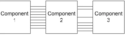
To give an example, imagine a modest system which divides logically into three components connected in sequence. In constructing an abstract view of the system, what we really want is to draw something like Figure 1 in which the detail inside each of the abstract components is hidden along with the detail inside the interconnections between them but what we get is more like Figure 2. The low level detail of the internal working of the components is hidden along with the wholly internal communications, but where connections are made between the components, these are simply brought to the edge of the box unchanged. As a result, instead of making the single logical connection between components, the modeller wishing to connect components has to knit them together using connections at the most concrete level. To do this successfully they need to know about, and understand, every detail of how the components interact and communicate.
Figure 2: What we get using a naïve notion of abstracting detail
A second problem which arises with the implementation of systems for abstraction which is no longer visible when the model is completed is that they operate on the complete concrete model. So the modeller is required to start by generating the complete, fully detailed description of their model. Only then are they permitted to draw the outlines of the abstract elements of the model and hide the contents. In other words, the modeller has to build their model from the bottom up and is only able to take advantage of hierarchical features when the model generation task is finished, although in fact these features would be most helpful during the construction of the model.
We use RDT to illustrate how hierarchical features without these drawbacks can be incorporated into a graphically based formal modelling language.
2.
The RDT modelling language
RDT was developed as a formal modelling language for use by users who wished to gain benefits from working with executable models in return for only a modest investment in learning about formal modelling.
RDT [15-17] is a good start. It uses diagrams motivated by Role Activity Diagrams [12] in place the of the more usual process algebra and these diagrams are accessible to readers from non-formal methods backgrounds. These diagrams are generated by the modeller providing the minimum of information to a tool which then generates and displays the diagrams automatically. There is also an execution tool and a conversion tool which are able to take completed models and execute them or convert them to Promela code for exhaustive analysis using the SPIN [5, 6] model checker.
RDT is a small language with just three event types. Between them, these are just enough to permit the modeller to construct any processes they might wish to use. In fact they have been shown to be sufficient to provide the essential features of the pi-calculus [10, 11, 14].
However, whilst the language has sufficient power to represent complex systems, the first implementation did not provide a mechanism for abstraction so any model has to be constructed and viewed in a form which displays every detail of the model. If an abstract view of a system is to be modelled, it is left to the modeller to abstract away unnecessary detail before commencing work with RDT.
3.
Larger models in RDT
The fundamental events of RDT operate at a low level of abstraction. Some types of operation which the modeller would like to describe, particularly those which would naturally involve the use of data, lead to complex processes with intricate connections to their neighbours. In part this is because processes are not able to inspect the values they receive on channels. A process in RDT has a named state which generally changes when the process takes part in an event. Essentially, the processes hold no data outside their named state. When a process is to receive a value which it will act on as data, it cannot inspect the value it receives on some channel as “input” and act accordingly. Instead, the discrimination of value has to be inferred from the channel on which the communication takes place. A process is then able to move to an appropriate, explicitly named state according to which event actually takes place. This scheme is effective but does lead to complex processes and models in which process instances are connected by many channels.
The algorithm works with a collection of nodes connected into a ring. Each node receives messages from one of their two neighbours and sends messages to their other neighbour. The behaviour of a node is as follows:
• Provided one is not already in progress, any node may decide to call an election by sending a message to its neighbour announcing an election and appending their id number.
• When a node receives a message announcing an election, it compares the number attached with its own. If the number in the message is higher than its own, it passes the message on unchanged. If the number in the message is lower, the node replaces it with its own before passing on the message. If the number appended to the message is the node’s own number then the node sends a message claiming to be the new leader.
• A node receiving a message naming the new leader notes the fact and passes the message on to the next unchanged unless it is the new leader (when it does nothing).
As the message from the node which initiates the election passes around the ring, the number attached to the message is increased each time it arrives at a node with a higher number. When a node receives the message back with its own number in it, that node can deduce that the message has passed all the way around the ring because that is the only way the message can come back. The fact that the message has the node’s own number attached means that on its journey around the ring it has not passed any node with a larger number. Consequently this node must have the highest number and be the new leader. As the new leader, the node sends a message around informing all the others of the identity of the new leader. This time, when the message returns, the new leader knows that all of the others know the identity of the new leader and the algorithm is finished.
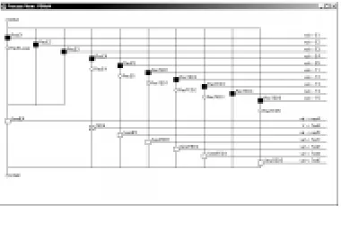
[image:3.612.336.526.78.206.2]Building a model of a system which uses this algorithm illustrates the problem we wish to address nicely. RDT has the power to model such a system, but the interconnections between the components required are quite intricate. Figure 3 shows an example implementation in RDT of a process from such a model. This process is constructed to be one node in the cycle algorithm. It has approaching twenty connections to the outside but they must all connect to one of its two neighbours in the ring.
Figure 3: An example cycle algorithm process
[image:3.612.334.529.317.564.2]Figure 4 shows an RDT model diagram in which three instances of these processes similar to that in Figure 3 are connected together in a cycle to form a complete model. The number of connections between the processes has resulted in a diagram which is already cluttered with just three nodes in the ring.
Figure 4: An Example Model of the Cycle Algorithm
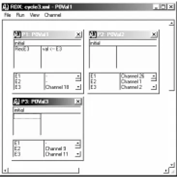
processes is hidden since their windows only show the current named state of the process and a list of those events which the process is presently able to initiate. The complexity of the interconnections is apparent in the number of channels in the model but, to drive the model, the user only interacts with the process windows so the channel windows can be hidden without interfering with the execution of the model. The channel windows provide additional (low level) information which the modeller can inspect should they wish to. Figure 5 shows the model defined in Figure 4 running in RDX.
Figure 5: RDX running the cycle algorithm model with three nodes
4.
Hierarchy in RDT
If an abstraction method is to be helpful, it needs to provide the modeller with a mechanism which permits them to step back from the detailed operation of the pieces in their model and look at a more generalised view. In addition, this abstraction mechanism should ideally permit the modeller/system designer to start at the higher levels of abstraction and fill in the details later. It should also address the issue of “wire syndrome” and provide the modeller with mechanisms which they can use to conceal the complexity of the interconnections between the various parts of their model.
In many modelling languages [4, 8, 9, 11], processes may be constructed from a collection of other processes. The final system is built by creating an instance of one of these compound processes. Implicit in this mechanism of creating the compound process is some ambiguity about whether process descriptions relate to a class of behaviour or an instance of a class of behaviour. In contrast, RDT
makes a much sharper distinction between types and instances of process. A process diagram describes a class of behaviour, the way that a process of this type behaves. The model diagram relates to instances. It describes how a collection of instances of processes are connected together to construct an executable model. This distinction was made in this way to help the novice or non-technical user to identify with the nature of the section of their model on which they are working. From observation, these users are inclined to slip into thinking in terms of an instance of the process they are describing even when the description they are working with is necessarily concerned with the behaviour of this type of process in general.
Looking at the model of the cycle election algorithm again, there is a clear need here for the finer detail of the interconnections to be eliminated if the modeller is to form a high level view of this model and the connections between the processes within it. We have something which looks like Figure 1 and we would like something which looks more like Figure 2. There is another benefit to be obtained from addressing this problem which would be particularly beneficial to the modeller. Looking at the cycle leader election model as an example once more, to complete the model, the modeller has to make a considerable number of connections between the various processes. This operation can be time consuming and is a potential source of errors. However, these connections are in fact systematic with the same connections repeated between each pair of neighbours. The task of making these connections would be considerably simplified and errors eliminated if the modeller were able to make them at the abstract level. In keeping with the general philosophy of RDT, the model generation tool could then complete the details automatically.
5.
Implementing Hierarchical Features in
RDT
Without both of these mechanisms in place, the modeller will never be free of the need to consider and understand the most detailed inner workings of the pieces they use in their model. It is also important to make these features available to the modeller early in the model generation activity.
RDT already has a single level of process abstraction: the model diagram shows instances of the processes which combine to form the model but the internal details of the processes are concealed. Work is in progress which will permit the modeller using the model generation tool to work with a more abstract view of their model by selecting some number of process instances to be combined into a single compound process in the familiar manner.
The other aspect, that of hiding the low level details is addressed with a new concept added to RDT – the connector. A connector provides an abstract description of the connection between two processes at the model lever (or higher). A connector has a name and the most minimal description of one does no more than give it a name. The modeller is then able to use instances of this connector to join processes in a model diagram. Figure 6 shows the way the cycle model from Figure 4 appears when drawn using connectors. In this example, all of the interconnections between the processes are contained within the connectors, but the modeller may also add individual connections at the channel level should they wish (which are shown using thin lines as on the standard model diagram).
As some point in the detailing of the processes, the modeller needs to specify what is concealed within each connector. This detail comprises pairs of channel names which are to be connected. If the modeller has created (even partially) the low level description of the processes in the model, the tool will be able to offer a list of the available channel names that appear in the processes defined in the model for the modeller to pick from, otherwise the modeller will need to create their own channel names as they work. Alternatively, if the modeller chooses to detail the connections which exist within the connectors they are using in advance of completing the inner detail of a process, the tool will be able to offer candidate names for communications channels derived from the names used within the connectors. When describing a connector, the modeller specifies the names of channels at each end of the connector. It is to be expected that the names at either end of the connector will be chosen to make sense to the modeller as they construct the detail of the processes at either end. Consequently the names at either end will not be same making the two ends of the connector different. This is the reason for the arrowheads on the connectors shown in Figure 6. They don’t imply anything about the direction of the
communication which passes along them which is expected, in general, to pass in both directions. They simply serve to distinguish one end of the connector from the other. There is no particular benefit to drawing a picture of a connector in isolation, but if we did it would look something like Figure 7.
ÿþýüýÿûúùøþ
ÿþýüýÿûúùø
ÿþýüýÿûúùø
ýýýýýþ
[image:5.612.328.506.160.449.2]ýýýýýþ
ýýýýýþ
Figure 6: The cycle model using Connectors
When a connector is joined to a process, the effect is as if all channel names used by the process for communication are joined to the correspondingly named strand at the appropriate end of the connector. So, taking the connector in Figure 7 as an example, if the end with the arrowhead is joined to a process which uses channels named, Ch A, to Ch D, these will be connected (pair-wise) to channels in the other process names Ack, Send, Rec., and Sig. The creation of these multiple associations will be handled for the modeller by the tool. If the modeller desires, the RDT model generation tool will display the model diagram showing the fully detailed connections between the processes.
connector to a process which has only some of the channel names of that end of the connector.
Figure 7: A connector
However, in order to ensure that the behaviours of models created with and without connectors are consistent, it is necessary to stipulate that, strands in connectors cannot be connected at just one end. In the event that there is a match for a strand at one end of a connector but not at the other, no channel is associated with the matched end. The reason for this follows from the fact that RDT permits channels to be buffered. Using the simple, concrete connection of channels in the standard model diagram of RDT, it is not possible to create a channel which is connected at just one end. Therefore we cannot allow such a situation to be generated using connectors. The particular difficulty concerns events which are prevented from occurring in a process because the channels into which they write are not connected. If channels are buffered and a “dangling” channel were associated with such a name, the possibility arises the event may now occur as the process can write into the channel until it becomes full.
6.
Benefits from connectors
The major benefit to using connectors is that they permit modellers to manage and control the mass of connections that they need to make between process instances in the model diagrams of RDT by wrapping them up into multi-cored connections. By doing this they are able to hide the low level detail of the interconnections between process instances. It also
makes the diagrams both easier to create and easier to read.
Using connectors also permits modellers to create new models much more quickly. For example, a modeller wishing to experiment with the cycle algorithm described above by adding further process instances to the cycle would have a considerable task making the connections between the new collection of process instances one at a time. Using a connector, they could put in place the multitude of connections required much more quickly and with considerably reduced risk of error.
7.
Conclusion
Building and analysing formal models of distributed computer systems can assist developers considerably in creating correct systems but is not easy. Using a modelling language with a graphical interface helps to overcome the barrier presented by the process algebra based input languages used by many of the modelling languages. However, as the models grow in size, the diagrams can become cluttered and confusing.
RDT is an example of a graphically based formal modelling language. It has the power of the pi-calculus. In its original design, the RDT language was kept as small as possible and its associated tools were designed to be as simple as possible to use. However, its lack of hierarchical features places a practical limit on the size of the models which it can handle.
This paper outlines the desirable features of a scheme for hierarchical models and identifies a weakness in many of the schemes already available. They address issues relating to the hiding of low level detail within components, but don’t address the communications between them. We also describe enhancements which add hierarchical features to RDT. In particular it describes a new concept added to the language, the connector, which permits modellers to control and manage the connections between the process instances of an RDT model.
The implementation of these connectors has been carefully considered to ensure that the modeller is able to use the concept throughout the model building process.
8.
References
[1] M.M.K. Hashmi and A.C. Bruce, “Design and use of a system-level specification and verification methodology,” Design Automation Conference, 1995,
[2] P. Henderson and G.D. Pratten, “POSD - A Notation of Presenting Complex Systems of Processes,” First IEEE International Conference on
Engineering of Complex Systems, Ft. Lauderdale,
Florida, 1995, pp. 125-128.
[3] G.H. Hilderink, “Graphical modelling language for specifying concurrency based on CSP,” Software, IEE
Proceedings- [see also Software Engineering, IEE Proceedings], vol. 150, pp. 108-120, 2003.
[4] C.A.R. Hoare, Communicating sequential
processes: Prentice-Hall International, 1985.
[5] G.J. Holzmann, “The Model Checker SPIN,” IEEE
Transactions on Software Engineering, vol. 23, pp.
279-295, 1997.
[6] G.J. Holzmann, The Spin Model Checker: Primer
and Reference Manual: Addison Wesley, 2003.
[7] S. Leue and G. Holzmann, “v-Promela: a visual, object-oriented language for SPIN,” Object-Oriented
Real-Time Distributed Computing, 1999. (ISORC '99) Proceedings. 2nd IEEE International Symposium on,
1999, pp. 14-23.
[8] J. Magee and J. Kramer, Concurrency: State
models and Java Programs: John Wiley and Sons,
1999.
[9] R. Milner, Communication and Concurrency: Prentice Hall, 1989.
[10] R. Milner, “Elements of Interaction: Turing Award Lecture,”, vol. 36. Communications of the ACM, 1993.
[11] R. Milner, “The Polyadic pi-Calculus: a
Tutorial,” in Logic and Algebra of Specification, F. L. Hamer, W. Brauer, and H. Schwichtenberg, Eds.: Springer-Verlag, 1993.
[12] M.A. Ould, Business Processes - Modelling and
Analysis for Re-engineering and Improvement: John
Wiley and Sons, 1995.
[13] C. Szyperski, Component Software: Longman, 1998.
[14] D.N. Turner, “The Polymorphic pi-calculus: Theory and Implementation,”. Edinburgh: University of Edinburgh, 1995.
[15] R.J. Walters, “Automating Checking of Models built using a Graphically Based Formal Modelling Language,” 27th Annual International Computer
Software and Applications Conference (COMPSAC 2003), Dallas, Texas., 2003, pp. 98-104.
[16] R.J. Walters, “A Graphically Based Language for Constructing, Executing and Analysing Models of Software Systems,” 26th Annual International
Computer Software and Applications Conference (COMPSAC 2002), Oxford, 2002, pp. 363-369.
[17] R.J. Walters, “A Graphically based language for constructing, executing and analysing models of software systems,” in Electronics and Computer
Science. Southampton: University of Southampton,